CEPC APDR SRF and beam dynamics study Zhenchao

CEPC APDR SRF and beam dynamics study Zhenchao LIU 2016 -9 -2

Outline • • APDR SRF scheme Cavity requirement Phase and voltage analysis Booster
 • Avoid pretzel orbit • Accommodate more bunches at Z/W energy")
Advantage: bypass (pp) • Avoid pretzel orbit • Accommodate more bunches at Z/W energy • Reduce AC power with crab waist collision Problem: very low RF efficiency!! bypass (pp)

New idea:APDR
 C≈60")
New SRF layout-6 ring IP 1 RF station Double Ring (1 km/3 km) C≈60 km RF&DR center 30°equispaced IP 3

bunch 3. 3 us t 26. 7 us
 Acceleration method • New acceleration method for CEPC to")
Nonconstant Voltage and Phase (NVP) Acceleration method • New acceleration method for CEPC to solve RF efficiency • The bunches in a bunch train will be accelerated at different Vci • The bunches in a bunch train will be accelerated at different synchrotron phase to keep constant energy gain. • Vai=Vci*cosϕsi=C
 Number of IPs Energy (Ge. V)")
parameter for CEPC partial double ring (wangdou 20160325) Number of IPs Energy (Ge. V) Circumference (km) SR loss/turn (Ge. V) Half crossing angle (mrad) Piwinski angle Ne/bunch (1011) Bunch number Beam current (m. A) SR power /beam (MW) Bending radius (km) Momentum compaction (10 -5) IP x/y (m) Emittance x/y (nm) Transverse IP (um) x/IP y/IP VRF (GV) f RF (MHz) Nature z (mm) Total z (mm) HOM power/cavity (kw) Energy spread (%) Energy acceptance by RF (%) n Life time due to beamstrahlung_cal (minute) F (hour glass) Lmax/IP (1034 cm-2 s-1) Pre-CDR H-high lumi. H-low power W Z 2 120 54 3. 1 0 0 3. 79 50 16. 6 51. 7 6. 1 3. 4 0. 8/0. 0012 6. 12/0. 018 69. 97/0. 15 0. 118 0. 083 6. 87 650 2. 14 2. 65 3. 6 0. 13 2 6 0. 23 47 2 120 54 2. 96 15 2. 85 67 16. 9 50 6. 2 2. 5 0. 25/0. 00136 2. 45/0. 0074 24. 8/0. 1 0. 03 0. 11 3. 62 650 3. 1 4. 1 2. 2 0. 13 2 2. 2 0. 47 36 2 120 54 2. 96 15 2. 67 44 10. 5 31. 2 6. 2 2. 2 0. 268 /0. 00124 2. 06 /0. 0062 23. 5/0. 088 0. 032 0. 11 3. 53 650 3. 0 4. 0 1. 3 0. 13 2 2. 1 0. 47 32 2 80 54 0. 59 15 5 0. 74 400 26. 2 15. 6 6. 1 2. 4 0. 1/0. 001 1. 02/0. 003 10. 1/0. 056 0. 008 0. 074 0. 81 650 3. 25 3. 35 0. 99 0. 09 2 45. 5 54 0. 062 15 7. 6 0. 46 1100 45. 4 2. 8 6. 1 3. 5 0. 1/0. 001 0. 62/0. 0028 7. 9/0. 053 0. 006 0. 073 0. 12 650 3. 9 4. 0 0. 99 0. 05 1. 7 0. 3 1. 1 0. 24 0. 68 2. 04 0. 82 2. 96 0. 81 2. 01 0. 92 3. 09 0. 95 3. 09 8
 Circumference (km) SR loss/turn")
6 double ring/ Number of IPs Energy (Ge. V) Circumference (km) SR loss/turn (Ge. V) Half crossing angle (mrad) Piwinski angle Ne/bunch (1011) Bunch number Beam current (m. A) SR power /beam (MW) Bending radius (km) VRF (GV) f RF (MHz) Cavity No. Cavity gradient Accelerating phase CW power/cavity (k. W) Peak power/train (k. W) Total Power (MW) Cell/cavity Cavity/module Module/station Total module R/Q (Ω) G HOM loss factor/cavity (V/p. C) HOM power/cavity (k. W) Working Temperature(K) Q 0 τ(ms) QL Bandwidth(k. Hz) Detuning F (k. Hz) Stored energy/cavity(J) Frev(k. Hz) Gap length (us) η(RF to beam efficiency)(%) Vc decrease(%) TB/τ Pre-CDR PDR(HL) Zhaijiyuan 20160327&04 08 2 120 54 3. 1 0 0 3. 79 50 16. 6 53. 2 6. 1 6. 87 650 384 15. 8 63. 1 275 / 105. 6 5 4 6 96 514 268 1. 8 3. 6 2 4 E 10 1. 156 2. 36 e 6 0. 28 -0. 27 158. 7 5. 484 / 100 / / 2 120 54 2. 96 15 2. 85 67 16. 96 51 6. 2 3. 65 650 384 20. 6 35. 2 263. 4 2220 382. 5 2 6 10 64 206 268 0. 54 0. 8 2 2 E 10 0. 097 1. 97 e 5 3. 3 -1. 16 107. 4 5. 484 0. 3 -160 27% / 1. 7 APDR(HL VRF=3. 62) 2 120 54 2. 96 15 2. 85 22 x 3 17 50 6. 2 3. 62 650 384 20. 6 35. 2 -32. 3 260 2345 100. 4 2 8 8 48 206 268 0. 54 0. 838 2 2 E 10 0. 811 1. 656 e 6 0. 196 -0. 138 107. 4 5. 484 26. 7 ~100 3. 3 0. 0158 APDR (H-low power) APDR (Z) 2 120 54 2. 96 15 2. 67 15 x 3 10. 5 31. 2 6. 2 3. 53 650 384 20 33 -30. 9 163 1148 62. 7 2 8 8 48 206 268 0. 54 0. 485 2 2 E 10 1. 242 2. 536 e 6 0. 128 -0. 083 100 5. 484 26. 7 ~100 2. 2 0. 021 2 45. 5 54 0. 062 15 8. 5 0. 46 367 x 3 45. 4 2. 8 6. 1 0. 357/0/12 650 48/24 16. 2/21. 7 80. 2 -79. 8/58. 9 -56. 9 117/233 1237 5. 6 2/1 4/4 2/1 12/6 206/103 268 0. 54 0. 361/0. 18 2 2 E 10 2. 243/0. 507 4. 58 e 6/1. 03 e 6 0. 071/0. 314 -0. 234/-0. 520 65. 3/59. 1 5. 484 26. 7 ~100 2. 5/5. 3 0. 012/0. 053
 Bunch train passing Bunch train space")
Accelerator gradient decrease in one RF cavity (Z) Bunch train passing Bunch train space Final Eacc/Initial Eacc Assume matching Initial Eacc(MV/m) RF cycles Field evolution in cavity Field decrease vs. various initial field gradient of the cavity
 C≈62")
New SRF layout-8 ring IP 1 RF station Double Ring (1 km/3 km) C≈62 km RF&DR center 22. 5°equispaced IP 3

bunch 3. 3 us t 20 us
 Circumference (km) SR loss/turn")
8 double ring Number of IPs Energy (Ge. V) Circumference (km) SR loss/turn (Ge. V) Half crossing angle (mrad) Piwinski angle Ne/bunch (1011) Bunch number Beam current (m. A) SR power /beam (MW) Bending radius (km) VRF (GV) f RF (MHz) Cavity No. Cavity gradient Accelerating phase CW power/cavity (k. W) Peak power/train (k. W) Total Power (MW) Cell/cavity Cavity/module Module/station Total module R/Q (Ω) G HOM loss factor/cavity (V/p. C) HOM power/cavity (k. W) Working Temperature(K) Q 0 τ(ms) QL Bandwidth(k. Hz) Detuning F (k. Hz) Stored energy/cavity(J) Frev(k. Hz) Gap length TB (us) η(RF to beam efficiency)(%) Vc decrease(%) TB/τ Pre-CDR PDR(HL) Zhaijiyuan 20160 160327 327&0408 APDR(HL VRF=3. 62) APDR (H-low power) VRF=3. 53) APDR (Z) 2 120 54 3. 1 0 0 3. 79 50 16. 6 53. 2 6. 1 6. 87 650 384 15. 8 63. 1 2 120 54 2. 96 15 2. 85 67 16. 96 51 6. 2 3. 65 650 384 20. 6 35. 2 2 120 54 2. 96 15 2. 85 17 x 4 17 50 6. 2 3. 62 650 384 20. 6 35. 2 -33 2 120 54 2. 96 15 2. 67 11 x 4 10. 5 31. 2 6. 2 3. 53 650 384/768/192 20/20/20 33 -31. 6/33 -31. 6 2 120 54 2. 96 15 2. 67 11 x 4 10. 5 31. 2 6. 2 5. 16 650 498 22. 6 55. 3 -55 2 45. 5 54 0. 062 15 8. 5 0. 46 275 x 4 45. 4 2. 8 6. 1 0. 357/0. 12 650 48/16/16 16. 2/16. 3/32. 6 80. 1 -79. 9/58. 956. 9/58. 9 -58 275 / 105. 6 5 4 6 96 514 268 1. 8 3. 6 2 4 E 10 1. 156 2. 36 e 6 0. 28 -0. 27 158. 7 5. 484 / 100 / / 263. 4 2220 382. 5 2 6 10 64 206 268 0. 54 0. 8 2 2 E 10 0. 097 1. 97 e 5 3. 3 -1. 16 107. 4 5. 484 0. 3 -160 27% / 1. 7 260 1389 100. 4 2 6 8 64 206 268 0. 54 0. 838 2 2 E 10 0. 811 1. 656 e 6 0. 196 -0. 138 107. 4 5. 484 20 ~100 2. 5 0. 025 163. 3/81. 6/326. 6 843 62. 7 2/1/4 6/12/3 8/8/8 64/64/64 206/103/412 268 0. 54/0. 27/1. 08 0. 485/0. 24/0. 97 2 2 E 10 1. 242 2. 53 e 6 0. 128 -0. 083 100 5. 484 20 ~100 1. 6 0. 0098 126 843 62. 7 2 6(3, 2) 10(11) 126 206 268 0. 54 0. 485 2 2 E 10 2. 045 4. 18 e 6 0. 077 -0. 111 126. 9 5. 484 20 ~100 1 0. 0098 117/350 884 5. 6 2/2/1 6/2/2 1/1/1 8/8/8 206/103 268 0. 54/0. 27 0. 36/0. 18 2 2 E 10 2. 243/0. 76 4. 58 e 6/1. 55 e 6 0. 071/0. 209 -0. 234/-0. 347 65. 3/133 5. 484 20 ~100 1. 7/5. 3/2. 5 0. 0089/0. 0263

8 ring H-Low power mode 8 ring Z mode
 • Pcw<<Ppulse case: • There")
What is the best number of PDR? Voltage decrease(%) • Pcw<<Ppulse case: • There are 2 n PDR in the circumference(n=1, 2…). Number of PDR HL mode Number of PDR H-low power mode

What is the best voltage? • R/Q=Vc^2/ωU, assume Ppulse>>Pcw • • d, cavity effective length, q bunch charge, Nb bunches per train, Ncav cavity number. H-low power case: – q=42. 8 n. C, Vsr=2. 96 GV, Ncav =384 Nb=50 VRF (GV) Vc’/Vc Assume matching Vc’/Vc • Nb=11 VRF (V)

What is the best voltage? • R/Q=Vc^2/ωU, assume Ppulse>>Pcw • • d, cavity effective length, q bunch charge, Nb bunches per train, Ncav cavity number. H-low power case: – Nb=11, q=42. 8 n. C, Vsr=2. 96 GV, Assume matching & same gradient Ncav =384 Vc’/Vc Ncav =498 Vc’/Vc • Working VRF VRF (V)

LEP • Assume: – φe= 1 deg. , φs=116 deg. , φalign=3 deg. , Ib=0. 45 m. A, h=31324, Q=40000, Rs=774 MΩ(14 cavities) – V 0 (initial peak voltage)from 20 MV-100 MV – 2. 3 MV/cavity(acc. voltage) Vleft/V 0 Voltage decrease: 1 bunch ~1% 4 bunches ~4% APDR: 8 DR: 2. 5%(HL)5. 3/2. 5%(Z) 6 DR: 3. 3%(HL) V 0(V) Voltage drop is acceptable!
 • Pcw<<Ppulse case: • Larger synchrotron")
Phase shift Synchrotron phase of last bunch (degree) • Pcw<<Ppulse case: • Larger synchrotron phase will make smaller phase shift for the bunches in a bunch train for the same voltage drop • Large voltage drop should choose larger synchrotron phase • Large synchrotron phase means more cavities (more cost) 2% Vc decrease Phase shift 0% Vc decrease 4% Vc decrease 20% 10% 0% 2% 4% Synchrotron phase of first bunch (degree) 10% Vc decrease 20% Vc decrease
 • Pcw<<Ppulse case: • Larger synchrotron phase will make smaller phase")
Phase shift (degree) • Pcw<<Ppulse case: • Larger synchrotron phase will make smaller phase shift for the bunches in a bunch train for the same voltage drop • Large voltage drop should choose larger synchrotron phase • Large synchrotron phase means more cavities (more cost) 2% Vc decrease 4% Vc decrease 10% Vc decrease 20% Vc decrease Synchrotron phase of first bunch (degree)

CEPC APDR SRF Design APDR SRF Challenge Difficulty Methods CDR Phase stability ☆☆☆ Feedback control, injection control, phase stability, SR damping, … ± 0. 1% Voltage control ☆☆☆ Feedback control, ± 1% BBU ☆☆ Variation on bunch current, Low wake field excitation at bunch train length, High damping SC cavity, Radiation damping(wiggler), bunch spacing, feedback, … >500 m. A (Z>1 A) HOM damping ☆☆ Single cell beam pipe/slotted cavity(multi-cell), … 1 -3 k. W Longitudinal instability ☆☆ Transverse instability ☆☆ Impact bunch position control ☆☆☆ Input coupler ☆☆ Q 0 ☆☆ EP is very important 2 E 10 Cavity gradient ☆☆☆ 20. 6 MV/m&Q 0=2 E 10@2 K (☆☆) 32. 6 MV/m&Q 0=2 E 10@2 K (☆☆☆, lower the Q 0) H mode: 2 E 10 Z mode: > 5 E 9 130 k. W(1 cell), 260 k. W(2 cell); Z: 350 k. W(2 cell), 175 k. W(1 cell)

Cavity requirement

What is the best β? β=0. 3 β= P-/P+ β=4366 β=1 0. 8 t/τ P-, reflection power; P+, forward power. 0. 6 0. 4 t/τ 0. 2 0. 3

What is the best cavity for APDR? • R/Q=Vc 2/ωU • A lower R/Q can give a high U at the same cavity voltage (or gradient) • The gradient is more stable at higher U when the input power is not enough at the pulse period. • It is an opposite design scheme comparing with low-loss cavity or others • Reduced R/Q can also decrease the detuning frequency • R/Q Riris loss factor • Cavity can work at a lower gradient with the same U

Phase and voltage analysis

Power coupling Phasor diagram φs≠ 0 &ωg>ω0

Optimum coupling • With optimum coupling condition ig Vb ψ ib Vc ϕs Vg Ψ=-ϕs

Equispaced bunches • For equispaced bunches: • Consider H-Low power case, I 0=0. 021 m. A, Ra=206 x 2 x 1010, beta=7. 9 x 10³, ψ=-33 deg. =-0. 576 Vb=0. 021 x 206 x 2 x 1010 xcos(-0. 576)e-0. 576 i/(1+7. 9 x 10³)=-7. 7 x 10⁶+5 x 10⁶ i • The amplitude of Vb is 9. 2 MV Abs(Vb)=9. 2 MV Angle(Vb)=-0. 576 • Vc=20 MV/m*0. 46 m=9. 2 MV, ϕs=0. 576 So, Vb=Vc & ψ=-ϕs

APDR bunches • Bunch train case, Tb is the bunch time interval in bunch train; TB is the time interval between bunch trains. • Tb≠TB. • Tb<<TB&TB/td<<1 • Tb/td=2. 428 e-4, TB/td=0. 016, ϕs=33 deg. , f=650 MHz Tb TB

What is beam loading? • It is not a beam in the cavity!!! • It is the beam induced voltage in the cavity!!! • When TB/Td<<1, the multi-bunches induced a constant Vb

Non-equispaced bunches • Consider H-Low power case, it is equal to 11 x 4 bunches, I 0=0. 021 m. A/11=1. 91 x 10 -3 m. A, Ra=206 x 2 x 1010, beta=7. 9 x 10³, ψ=-33 deg. =0. 576, f=650 MHz, t’b=196 x 77/f=2. 322 x 10 -5 s, Q 0=2 x 10¹⁰ • Phase shift is 1. 4 deg. with 11 bunches, the phase shift between two bunches is 0. 14 deg. mb=196. So tb=195. 999611/f=3. 015 x 10 -7 s. • Also we need to assume there is no phase shift between the first bunch of 0. 14 deg. each bunch train. . Bunch 1 …. 196 x 2π . Bunch 2 ….
 One circle=308 tb Im(A) Re(A) • Vbr=Vih*A")
65 circles ~0. 012 s T (tb) One circle=308 tb Im(A) Re(A) • Vbr=Vih*A T (tb)
 Im(A) • Vbr=Vih*A, A for bunches in a bunch train after 400000 circles.")
Re(A) Im(A) • Vbr=Vih*A, A for bunches in a bunch train after 400000 circles. • Total phase shift of Vb is 1. 37 degree for 11 bunches. Bunch Vbr ≈ 1. 865 x 104 Vx 584. 5=1. 09 x 107 V With optimum matching of minimum Pg, ψ=-ϕs Vb=Vbrcos(-33°)=9. 14 MV As Vc=9. 2 MV, so Vb≈Vc Bunch

Vg 8 -ring: Bunch No. Re Vb Im Vb Re Vc Im Vc Re Vg Im Vg ABS Vg Vg Angle (deg. ) Vg Vg Angle shift (deg. ) 1 -7. 67 E+06 4. 98 E+06 7. 72 E+06 5. 01 E+06 1. 54 E+07 3. 05 E+04 1. 539 E+07 1. 0000 0 2 -7. 66 E+06 5. 00 E+06 7. 72 E+06 4. 99 E+06 1. 54 E+07 -6. 31 E+03 1. 537 E+07 0. 9991 -0. 13 0 3 -7. 64 E+06 5. 02 E+06 7. 72 E+06 4. 97 E+06 1. 54 E+07 -4. 31 E+04 1. 536 E+07 0. 9983 -0. 27 0 4 -7. 63 E+06 5. 03 E+06 7. 72 E+06 4. 95 E+06 1. 53 E+07 -7. 98 E+04 1. 535 E+07 0. 9974 -0. 41 0 5 -7. 62 E+06 5. 05 E+06 7. 72 E+06 4. 94 E+06 1. 53 E+07 -1. 16 E+05 1. 533 E+07 0. 9966 -0. 54 0 6 -7. 60 E+06 5. 07 E+06 7. 72 E+06 4. 92 E+06 1. 53 E+07 -1. 53 E+05 1. 532 E+07 0. 9958 -0. 68 0 7 -7. 59 E+06 5. 09 E+06 7. 72 E+06 4. 90 E+06 1. 53 E+07 -1. 89 E+05 1. 531 E+07 0. 9949 -0. 82 0 8 -7. 58 E+06 5. 10 E+06 7. 72 E+06 4. 88 E+06 1. 53 E+07 -2. 26 E+05 1. 530 E+07 0. 9941 -0. 96 0 9 -7. 56 E+06 5. 12 E+06 7. 72 E+06 4. 86 E+06 1. 53 E+07 -2. 62 E+05 1. 528 E+07 0. 9933 -1. 09 0 10 -7. 55 E+06 5. 14 E+06 7. 72 E+06 4. 84 E+06 1. 53 E+07 -2. 98 E+05 1. 527 E+07 0. 9924 -1. 23 0 11 -7. 54 E+06 5. 16 E+06 7. 72 E+06 4. 82 E+06 1. 53 E+07 -3. 34 E+05 1. 526 E+07 0. 9916 -1. 37 0
 ig Vb")
Phase evolution • With optimum coupling condition (H low power 8 ring) ig Vb 11 Vc=9. 2 MV Vb 1 Vc 1 Vb=9. 2 MV ψ ib ϕs Vc 11 Vg 11 Ψ=-ϕs Vg=15. 43 MV 1. 37 degree
 PDR (CW, Pg=Ppulse, very low RF efficiency) APDR")
Bunch No. Pre CDR (CW, Pg=Pavg) PDR (CW, Pg=Ppulse, very low RF efficiency) APDR 8 ring (HL, CW, Pg=Pavg) APDR 8 ring (Hlow power, CW, Pg=Pavg) APDR 8 ring (Z, Pg=Pavg) Vc Vc Vc Phase shift Phase shift 1 1 0 1 2. 00 1 1. 40 1 2. 0000 2 1 0 0. 9984 1. 88 0. 9984 1. 26 0. 9998 1. 9927 3 1 0 0. 9969 1. 75 0. 9968 1. 12 0. 9996 1. 9855 4 1 0 0. 9953 1. 63 0. 9952 0. 98 0. 9994 1. 9782 5 1 0 0. 9938 1. 50 0. 9936 0. 84 0. 9992 1. 9709 6 1 0 0. 9922 1. 38 0. 992 0. 70 0. 9990 1. 9636 7 1 0 0. 9906 1. 25 0. 9904 0. 56 0. 9988 1. 9564 8 1 0 0. 9891 1. 13 0. 9888 0. 42 0. 9987 1. 9491 9 1 0 0. 9875 1. 00 0. 9872 0. 28 0. 9985 1. 9418 10 1 0 0. 9859 0. 88 0. 9856 0. 14 0. 9983 1. 9345 11 1 0 0. 9844 0. 75 0. 984 0 0. 9981 1. 9273 15 1 0 0. 9781 0. 25 0. 9973 1. 8982 17 1 0 0. 9750 0 0. 9969 1. 8836 50 1 0 0. 9906 1. 6436 1 0 0. 9873 1. 5200 67 275 Assume Vrf is constant at the first bunch of bunch trains and the change of Vb is negligible. 0. 0947 0
 PDR (CW, Pg=Ppulse, very low RF efficiency) APDR")
Bunch No. Pre CDR (CW, Pg=Pavg) PDR (CW, Pg=Ppulse, very low RF efficiency) APDR 6 ring (Hlow power, CW, Pg=Pavg) APDR 6 ring (HL, CW, Pg=Pavg) APDR 6 ring (Z, Pg=Pavg) Vc Vc Vc Phase shift 1 1 0 1 2 1 0 3 1 0 1 4 1 0 5 1 6 Phase shift 1 2. 6000 0. 9984 2. 04 0. 9984 2. 48 0. 9998 2. 5929 0 0. 9968 1. 89 0. 9969 2. 35 0. 9996 2. 5858 1 0 0. 9952 1. 73 0. 9953 2. 23 0. 9994 2. 5787 0 1 0 0. 9936 1. 57 0. 9937 2. 10 0. 9992 2. 5716 1 0 0. 992 1. 41 0. 9921 1. 98 0. 9989 2. 5645 7 1 0 0. 9904 1. 26 0. 9906 1. 86 0. 9987 2. 5574 8 1 0 0. 9888 1. 10 0. 9890 1. 73 0. 9985 2. 5503 9 1 0 0. 9872 0. 94 0. 9874 1. 61 0. 9983 2. 5432 10 1 0 0. 9856 0. 79 0. 9859 1. 49 0. 9981 2. 5361 11 1 0 0. 984 0. 63 0. 9843 1. 36 0. 9979 2. 5290 15 1 0 0. 9776 0 0. 9780 0. 87 0. 9971 2. 5005 22 1 0 0 0. 9956 2. 4508 50 1 0 0. 9897 2. 2519 1 0 0. 9861 2. 1311 67 2. 20 Phase shift 0. 9670 367 Assume Vrf is constant at the first bunch of bunch trains and the change of Vb is negligible. 0. 0923 0

Bunch position • The e+ and e- bunch trains should be symmetry to the two IPs. • The phase shift of the synchrotron phase between each bunch in a bunch train is 0. 14 degree for the H low power mode. The total phase shift is 1. 4 degree. • After enough synchrotron damping, the bunches will be at its synchrotron phase separately. • If the transport matrix from cavity to IP is the same for e+ and e- bunch trains, there will be no shift for the position of colliding. RADIATION DAMPING, R. P. Walker

Power reflection • In resonant operation: • For heavy beam loading, Pc<<Pb, • For APDR steady state, Pb is constant. We make the first bunch of bunch train at optimal coupling, then Pg=Pb. Pr=0 • The generator power is • Which simplifies to H. Padamsee, RF superconductivity for accelerators, P 387, P 396

The first bunch of bunch train working at different synchrotron phase • The beam induced voltage and generator induced voltage are related with β. • Vc can be increased by lower β. • By increasing Vc and φs, keeping Vc*cos (φs)=C, →Pb is constant, Pg is constant. So

Bunches in a bunch train • In we set the β optimal to the first bunch, then the β is not optimal to others. The Pg needed for the last bunches is a little higher. But only 0. 025% Pg (W) • For example, H low power case, If we set β=7914 for the first 。 bunch, keeping Pb constant (161. 5 k. W). Pc=20. 42 W→Eacc=20 MV/m. The last bunch, Pc=19. 8 W Last bunch 1 st bunch Pc (W)

Booster Parameters • Parameter List for Alternating Magnetic Field Scheme. Parameter Unit Value Beam energy [E] Ge. V 6 Circumference [C] km Revolutionfrequency[f 0] Unit Value RF voltage [Vrf] GV 0. 2138 63. 84 RF frequency [frf] GHz 1. 3 k. Hz 4. 69 Harmonic number [h] SR power / beam [P] MW 2. 16 Synchrotronoscillationtune[ns] Beam off-set in bend cm 1. 2 Energy acceptance RF Momentum compaction factor[α] Strength of dipole 2. 33 E-5 Gs n. B/beam -129. 18/+180. 84 50 Lorentz factor [g] 11741. 71 Magnetic rigidity [Br] T·m 20 Beam current / beam [I] m. A 0. 92 Bunchpopulation[Ne] Bunch charge [Qb] emittance-horizontal[ex] inequilibrium injected from linac emittance-vertical[ey] inequilibrium injected from linac 2. 44 E 10 n. C 3. 91681 m·rad 6. 38 E-11 m·rad 3 E-7 m·rad 0. 191 E-11 m·rad Parameter SR loss / turn [U 0] Energyspread[sd] inequilibrium injected from linac Bunch length[sd] inequilibrium injected from linac Transversedampingtime[tx] 276831 0. 21 % 5. 93 Ge. V 5. 42 E-4 % 0. 0147 % 0. 1 mm 0. 18 mm ~1. 5 ms 4. 71 turns Longitudinaldampingtime[t e] ms 4. 71 turns 3 E-7 Tianjian Bian

Booster Parameters • Parameter List for Alternating Magnetic Field Scheme. Parameter Unit Value Beam energy [E] Ge. V 120 Circumference [C] km Revolutionfrequency[f 0] Unit Value RF voltage [Vrf] GV 6 63. 84 RF frequency [frf] GHz 1. 3 k. Hz 4. 69 Harmonic number [h] SR power / beam [P] MW 2. 16 Synchrotronoscillationtune[ns] Beam off-set in bend cm 0 Momentum compaction factor[α] Strength of dipole Gs n. B/beam 400 Beam current / beam [I] m. A 0. 92 Bunch charge [Qb] emittance-horizontal[ex] inequilibrium injected from linac emittance-vertical[ey] inequilibrium injected from linac 2. 44 E 10 n. C 3. 91681 m·rad 3. 61 E-9 m·rad 3 E-7 m·rad 0. 1083 E-9 m·rad Ge. V 2. 34 % 0. 12 % 0. 1 mm 1. 36 mm ~1. 5 Transversedampingtime[tx] ms 21. 76 Longitudinaldampingtime[t e] ms Energyspread[sd] inequilibrium T·m 0. 21 4. 57 516. 71 Magnetic rigidity [Br] 276831 % SR loss / turn [U 0] 234834. 15 Bunchpopulation[Ne] Energy acceptance RF 2. 54 E-5 50 Lorentz factor [g] Parameter injected from linac Bunch length[sd] inequilibrium injected from linac 3 E-7 Tianjian Bian
 89. 855° • Extract phase (120 Ge.")
Synchrotron Phase • Inject phase (6 Gev) 89. 855° • Extract phase (120 Ge. V)67. 046° • Synchrotron phase φs=arccos(Vsr/Vrf) Synchrotron phase (degree) – Assume Vrf linearly increases Beam energy (Ge. V)

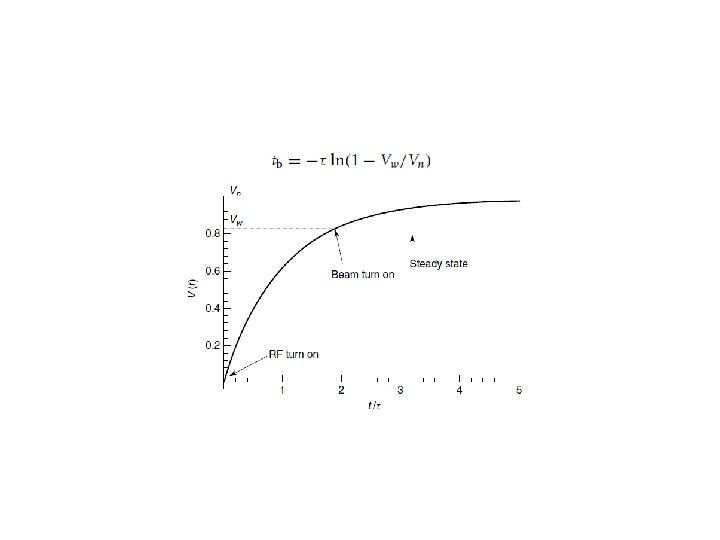
Conclusion • The 8 -double ring and 6 -double ring are available when using the same parameter as PDR(VRF=3. 62 GV) for HL. The 8 -double ring has a lower phase variation than the 6 -double ring. • The phase region is from 35. 2 -33 degree for bunches in a bunch train for the 8 -double ring HL mode. The phase region is from 35. 232. 3 degree for the 6 -double ring HL mode. • The bunch energy gain in each cavity is constant. • The RF to beam efficiency is ~100%. • Vb is 9. 14 MV with a 1. 37 deg. phase shift in a bunch train of the APDR H low power of 8 ring case. • Vb reaches constant value after about 65 circles (Ib=C, ~0. 012 s). • Beam can be stored by increasing bunch charges stably (with reflection in low current). • Vc should keep constant phase and value for each bunch separately.

Thanks!
- Slides: 47