CEPC accelerator physics Chenghui Yu for CEPC team


 – Higgs")


 120 80 45.")


 Magnetic length (m) Coil")


 3, SC Magnet and Vacuum chamber")


")

- Slides: 47
CEPC accelerator physics Chenghui Yu for CEPC team Feb. 10, 2018
Outline • Physics goals and collider parameters • Physics design of CEPC Linac Booster Collider ring • Summary
Physics goals of CEPC Electron-positron collider (45. 5, 80, 120 Ge. V) – Higgs Factory • Precision study of Higgs (m. H, JPC, couplings) • Looking for hints of new physics • Luminosity > 2. 0× 1034 cm-2 s-1 – Z & W factory • Precision test of standard model • Rare decays • Luminosity > 1. 0× 1034 cm-2 s-1
Physics design of CEPC Linac Booster Collider ring 100 km circumference, double ring collider with 2 IPs Matching the geometry of SPPC as much as possible Adopt twin-aperture quadrupoles and dipoles in the ARC
Physics design of CEPC Linac 1200 m Parameter Symbol Unit Baseline Designed e- /e+ beam energy Ee-/Ee+ Ge. V 10 10 frep Hz 100 > 9. 4× 10⁹ 1. 9× 10¹⁰ / 1. 9× 10¹⁰ > 1. 5 3. 0 < 2× 10 -3 1. 5× 10 -3 / 1. 6× 10 -3 < 120 5 / 40 ~120 Repetition rate e- /e+ bunch population Ne-/Ne+ n. C Energy spread (e- /e+ ) σe Emittance (e- /e+ ) εr nm rad Bunch length (e- /e+ ) σl mm 1/1 e- beam energy on Target Ge. V 4 4 e- bunch charge on Target n. C 10 10
Physics design of CEPC Transport Line 1 ~650 m 0 ~ -100 m Transfer efficiency 99%
Physics design of CEPC Booster Injection energy 10 Ge. V FODO cells with 90 degrees phase shift • The diameter of the inner aperture is selected as 55 mm due to limitation of impedance. • The beam lifetime should be higher than 14 min (3% particle lose) according to the duration before extraction.
Physics design of CEPC Booster Injection time structure 1 cycle 4 cycles 30 Gauss @ 10 Ge. V 9 cycles Eddy current effect
Physics design of CEPC Higgs W Z Injection Energy (Ge. V) 120 80 45. 5 Bunch number 242 305 600 Bunch Charge (n. C) 0. 72 0. 38 Beam Current (m. A) 0. 52 0. 66 0. 69 Beam current threshold due to TMCI (m. A) Number of Cycles 0. 803 1 4 20 Current decay 3% 3% 3% Ramping Cycle (sec) 10. 0 6. 6 3. 8 26 86 592 Collider Lifetime (hour) 0. 33 3. 5 7. 4 Injection frequency (sec) 37 383 811 Injection time (sec) Booster Transfer efficiency is 92% if beam lifetime is 14 min.
Booster Physics design of CEPC Error studies Errors Setting Dipole Quadrupole Sextupole Corrector Transverse shift X/Y (μm) 100 100 Longitudinal shift Z (μm) 150 150 Tilt about X/Y (mrad) 0. 1 0. 2 Tilt about Z (mrad) 0. 05 0. 2 Nominal field 1 e-3 1 e-2 BPM Accuracy (m) 1 e-5 Tilt (mrad) 10 Gain 5% Offset after BBA(mm) 1 e-3
Physics design of CEPC Booster Orbit with errors • Orbit within the beam stay clear • “First turn trajectory” is not necessary Horizontal Corrector: 48 correctors +856 BTs Vertical Corrector : 904 correctors BPM : 904*2 Hor. 0. 2 mm Ver. 0. 3 mm
Physics design of CEPC Booster Beta Beating, Emittance and Dynamic Aperture with errors • • Nearly half of bare lattice, 50 mm* 18 mm, without optics correction, satisfy requirement Emittance growth is less than 10% for the simulation seeds Satisfy the requirement of injection and beam lifetime Skew quadrupoles are needed to control the coupling βx/βy=188/33 m =120 nm : 2(9 x +5 mm) / 2(6 y +5 mm) Hor. 10% Ver. 6. 5% Hor. 0. 023 m Ver. 0. 04 m
Physics design of CEPC Booster On-axis injection and extraction Damping time 87 s • • e+ and e- beams are injected from outside of the booster ring Horizontal septum is used to bend beams into the booster A single kicker downstream of injected beams kick the beams into the booster orbit Extraction is the opposite procedure
Physics design of CEPC Transport Line 2 ~ 850 m 1. 5 m Transfer efficiency 99% • The total transfer efficiency > 90% (99%*92%*99%) • Satisfy the requirement of topup operation for H, W and Z
Physics design of CEPC Collider ring The geometry of CEPC is compatible with the SPPC as much as possible
Parameters of CEPC collider ring Higgs @ 3 T Number of IPs Energy (Ge. V) Circumference (km) SR loss/turn (Ge. V) Half crossing angle (mrad) Piwinski angle Ne/bunch (1010) Bunch number (bunch spacing) Beam current (m. A) SR power /beam (MW) Bending radius (km) Momentum compaction (10 -5) IP x/y (m) Emittance x/y (nm) Transverse IP (um) x/ y/IP VRF (GV) f RF (MHz) (harmonic) Nature bunch length z (mm) Bunch length z (mm) HOM power/cavity (kw) Energy spread (%) Energy acceptance requirement (%) Energy acceptance by RF (%) Photon number due to beamstrahlung Lifetime _simulation (min) Lifetime (hour) F (hour glass) Lmax/IP (1034 cm-2 s-1) W @ 3 T 2. 58 15 2 80 100 0. 34 16. 5 7. 74 15 242 (0. 68 us) 1220 (0. 27 us) 17. 4 30 87. 9 30 10. 6 1. 11 0. 36/0. 0015 0. 54/0. 0016 13. 9/0. 049 0. 013/0. 12 0. 47 650 (216816) 2. 98 6. 53 0. 87(2 cell) 0. 066 0. 4 1. 47 0. 44 120 1. 73 0. 36/0. 0015 1. 21/0. 0031 20. 9/0. 068 0. 031/0. 109 2. 17 2. 72 3. 26 0. 54 (2 cell) 0. 1 1. 35 2. 06 0. 29 100 0. 67 (40 min) 0. 89 2. 93 2 0. 94 11. 5 Z @ 2 T 45. 5 0. 036 23. 8 8. 0 12000 (25 ns+10%gap) 461 16. 5 0. 2/0. 001 0. 17/0. 0016 5. 9/0. 04 0. 0041/0. 072 0. 1 2 T 3 T 0. 2/0. 0015 0. 17/0. 004 5. 9/0. 078 2. 42 8. 5 1. 94(2 cell) 0. 038 0. 23 1. 7 0. 55 4 0. 99 32. 1 16. 6
Start from detector solenoid 3. 0 T Emittance growth caused by the fringe field of solenoids Design emit. Y/emit. X H: 3. 6 pm/1. 21 nm (0. 3%) W: 1. 6 pm/0. 54 nm (0. 3%) Z: 1. 0 pm/0. 17 nm (0. 5%) expected contribution 0. 36 pm 0. 16 pm 0. 09 pm real contribution 0. 14 pm (0. 01%) 0. 47 pm (0. 09%) 2. 9 pm (1. 7%)
Start from detector solenoid 3. 0 T βy* Vs. coupling @ Z Limitation of the luminosity improvement by reducing the βy*
Start from detector solenoid 3. 0 T Coupling=1. 7% + 0. 3~0. 5% Large beam size & serious bunch lengthening • Set the detector solenoid at 2 T Higher luminosity & Lower difficulty of SC magnet & More free space nearby IP • Only set the detector solenoid at 2 T or < 2 T during Z operation Only higher luminosity @ Z
The design of interaction region The definition of beam stay clear • To satisfy the requirement of injection: BSC > 13 x • To satisfy the requirement of beam lifetime after collision BSC > 12 y Beam tail distribution with full crab-waist BSC>13 x BSC>12 y BSC_x = (18 x +3 mm), BSC_y = (22 y +3 mm), While coupling=1%
The design of interaction region L*=2. 2 m, c=33 mrad, βx*=0. 36 m, βy*=1. 5 mm, Detector solenoid=3. 0 T – Lower strength requirements of anti-solenoids (~7. 2 T) – Enough space for the SC quadrupole coils in two-in-one type (Peak field 3. 8 T & 136 T/m) with room temperature vacuum chamber. – The control of SR power from the superconducting quadrupoles.
The design of interaction region The inner diameter of the beryllium pipe is 28 mm with the length of 7 cm. Without tungsten shield.
The design of interaction region Superconducting QD coils Rutherford Nb. Ti-Cu Cable Single aperture of QD 0 (Peak field 3. 2 T) Room-temperature vacuum chamber with a clearance gap of 4 mm Magnet Central field gradient (T/m) QD 0 136 Magnetic Width of Beam stay length (m) clear (mm) 2. 0 19. 51 Min. distance between beams centre (mm) 72. 61 *10 -4 Field cross talk of two coils
The design of interaction region Superconducting QD coils The conductor for the shield coil is round Nb. Ti wire with diameter of 0. 5 mm. There are 44 turns in each pole with different length to optimize the field harmonics along the QD coil. *10 -4 Two layers of shield coil are introduced outside the QD coil to improve the field quality. Integral field harmonics with shield coils(× 10 -4) n 2 3 4 5 6 7 8 9 10 Bn/B 2@R=9. 8 mm 10000 -0. 57419 1. 525573 0. 375555 -0. 13735 0. 015413 -0. 03117 -1. 70 E-03 -0. 05809
The design of interaction region Superconducting QD coils There is iron yoke around the quadrupole coil for QF 1. Since the distance between the two apertures is larger enough and the usage of iron yoke, the field cross talk between two apertures of QF 1 can be eliminated. One of QF 1 aperture (Peak field 3. 8 T) Rutherford Nb. Ti-Cu Cable Room-temperature vacuum chamber with a clearance gap of 7 mm Magnet Central field gradient (T/m) QF 1 110 Magnetic Width of Beam stay length (m) clear (mm) 1. 48 27. 0 Min. distance between beams centre (mm) 146. 20 Integral field harmonics with shield coils(× 10 -4) n 2 6 10 14 Bn/B 2@R=13. 5 mm 10000 1. 08 -0. 34 0. 002
The design of interaction region Magnet name Field gradient (T/m) Magnetic length (m) Coil turns per pole Excitation current (A) Shield coil turns per pole Shield coil current (A) Coil layers Conductor size (mm) Stored energy (KJ) Inductance (H) Peak field in coil (T) Coil inner diameter (mm) Coil outer diameter (mm) X direction Lorentz force/octant (k. N) Y direction Lorentz force/octant (k. N) QD 0 136 2. 0 21 2400 44 126 2 Rutherford Nb. Ti-Cu Cable, width 3 mm, mid thickness 0. 95 mm, keystone angle 1. 6 deg 19. 0 0. 007 3. 2 40 53 54 -112 Magnet name Field gradient (T/m) Magnetic length (m) Coil turns per pole Excitation current (A) Coil layers Conductor size (mm) Stored energy (KJ) Inductance (H) Peak field in coil (T) Coil inner diameter (mm) Coil outer diameter (mm) X direction Lorentz force/octant (k. N) Y direction Lorentz force/octant (k. N) QF 1 110 1. 48 29 2250 2 Rutherford Nb. Ti-Cu Cable, width 3 mm, mid thickness 0. 95 mm, keystone angle 1. 6 deg 30. 5 0. 012 3. 8 56 69 110 -120 Specification of QD 0 and QF 1
The design of interaction region 3 T & 7. 6 m Specification of Anti-Solenoid Anti-solenoid Central field(T) Magnetic length(m) Conductor (Nb. Ti-Cu, mm) Coil layers Excitation current(k. A) Inductance(H) Peak field in coil (T) Number of sections Solenoid coil inner diameter (mm) Solenoid coil outer diameter (mm) Total Lorentz force F z (k. N) Cryostat diameter (mm) Before QD 0 7. 2 1. 1 16 7. 7 4 -75 Within QD 0 2. 8 2. 0 2. 5× 1. 5 8 1. 0 1. 2 3. 0 11 120 390 -13 500 After QD 0 1. 8 1. 98 4/2 1. 9 7 88 22 anti-Solenoid sections with different inner coil diameters Bzds within 0~2. 12 m. Bz < 300 Gauss away from 2. 12 m with local cancellation structure The skew quadrupole coils are designed to make fine tuning of Bz over the QF&QD region instead of the mechanical rotation.
The design of interaction region Geometry and Lattice Crab-waist scheme with local chromaticity correction
The design of interaction region • The central part is Be pipe with the length of 14 cm and inner diameter of 28 mm. • IP upstream: Ec < 120 ke. V within 400 m. Last bend(66 m)Ec = 45 ke. V • IP downstream: Ec < 300 ke. V within 250 m, first bend Ec = 97 ke. V Reverse bending direction of last bends Background control & SR protection
The design of interaction region The total SR power generated by the QD magnet is 639 W in horizontal and 166 W in vertical. The critical energy of photons are about 1. 3 Me. V and 397 ke. V in horizontal and vertical. The total SR power generated by the QF 1 magnet is 1567 W in horizontal and 42 W in vertical. The critical energies of photons are about 1. 6 Me. V and 225 ke. V in horizontal and vertical. No SR hits directly on the beryllium pipe. SR power contributed within 6 x will go through the IP. 3 mask tips are added to shadow the beam pipe wall from 0. 7 m to 3. 93 m reduces the number of photons that hit the Be beam pipe from 2 104 to about 200 (100 times lower).
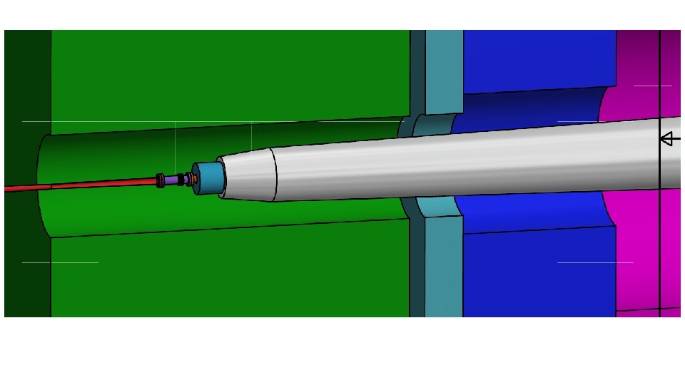
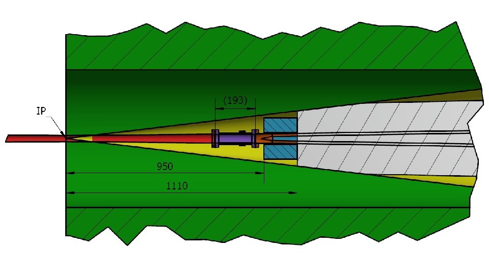
Assembly nearby the IP 1, IP Chamber (supporting) 3, SC Magnet and Vacuum chamber (remotely) 2, Bellows and Lumical (remotely) (supporting system) 4, Move Lumical back and attach to the cover of cryostat by alignment holes (remotely)
Assembly nearby the IP Crotch region Helicoflex
Physics design of CEPC Collider ring The ARC region – Distance of two ring is 0. 35 m to adopt twin-aperture Q & B magnets. – FODO cell, 90 /90 , non-interleaved sextupole scheme
Physics design of CEPC Collider ring The RF region – Common cavities for Higgs mode, bunches filled in half ring for e+ and e-. – Independent cavities for W & Z mode, bunches filled in full ring. – The outer diameter of RF cavity is 1. 5 m. Distance of two ring is 1. 0 m. Z mode: Bunch spacing > 25 ns
Physics design of CEPC Collider ring The RF region Low beta functions in the RF region to reduce the instabilities caused by RF cavities. For Z mode, due to the limitation of HOM 466 m. A can be chosen before the installation of the dedicated RF cavity. ~2. 0 km RF cavities Esep=1. 8 MV/m , Lsep=50 m
Physics design of CEPC Collider ring The injection region – Independent magnets for two rings – 0. 3 m of longitudinal distance between two quadrupoles of two rings. Phase tuning Injection Phase tuning βx=600 m at injection point,Injection section 66. 7 m
Physics design of CEPC Collider ring The injection For Higgs: e_x = 1. 21 nm. rad; e_inject = 3. 58 nm. rad x = 0. 85 mm, _inject = 0. 94 mm Septum = 2 mm Acceptance > 13 For Z: e_x = 0. 17 nm. rad; e_inject = 0. 51 nm. rad x = 0. 32 mm, _inject = 0. 357 mm Septum = 2 mm Acceptance > 17 Acceptance >4 xc + 6 xi + S
Physics design of CEPC Collider ring The injection Injected Beam Circulating Beam Local bump kickers Off-axis injection
Physics design of CEPC Crab waist=100% • • • Collider ring Dynamic aperture optimization SAD is used Code: MODE 200 turns tracked 100 samples IR sextupoles + 50 arc sextupoles (Max. free various=254) Damping at each element RF ON Radiation fluctuation ON Sawtooth on with tapering The requirements Minimum DA of 100 samples. 0. 26% coupling. 200 turns. Dynamic Aperture of on-momentum particles
Physics design of CEPC Crab waist=100% Collider ring Dynamic aperture optimization • SAD is used • 3000 turns tracked • IR sextupoles + arc sextupoles (Max. free various=254) • Damping at each element • RF ON • Radiation fluctuation ON • Sawtooth on with tapering • The requirements Z mode Minimum DA of 100 samples. 2. 4% coupling. 3000 turns. All effects (exception: errors and solenoid) is included in the dynamic aperture survey.
Physics design of CEPC Collider ring Beam performance with errors • LOCO based on AT is used to correct COD, beta, dispersion and coupling. • Tracking DA by SAD. • About 1500 BPMs, 1500 horizontal correctors and 1500 vertical correctors are placed in the storage ring. (4 per betatron wave) Component x (mm) y (mm) z (mrad) Dipole 0. 05 0. 1 Quadrupole w/o FF 0. 03 0. 1 Sextupole 0. 03 0. 1 Component Field error Dipole 0. 01% Quadrupole (w/o FF) 0. 02%
Physics design of CEPC Collider ring Beam performance with errors • • Residue COD 40 um (x) after orbit correction Residue COD 75 um (y) after orbit correction (βxy_err/βxy)max =0. 01 after optics correction Coupling=0. 08% after coupling correction 1/5 quadrupole (~600 of 3000 quadrupoles) are tuned to restore beta functions. It’s important to modify LOCO script to make the optics correction efficient and more parameters fitting possible. Skew-Quads are installed in the sextupoles. About 200 Skew-quads(1/5 sextupoles) are used in the coupling correction
Physics design of CEPC Collider ring The impedance and instabilities Components Number R, kΩ L, n. H Z||/n, mΩ Resistive wall - 15. 3 866. 8 16. 3 432. 3 23. 0 RF cavities 336 11. 2 -72. 9 -1. 4 315. 3 0. 41 Flanges 20000 0. 7 145. 9 2. 8 19. 8 2. 8 BPMs 1450 0. 53 6. 38 0. 12 13. 1 0. 3 Bellows 12000 2. 3 115. 6 2. 2 65. 8 2. 9 Pumping ports 5000 0. 01 1. 3 0. 02 0. 4 0. 6 IP chambers 2 0. 8 0. 02 6. 7 1. 3 Electro-separators 22 1. 5 -9. 7 0. 2 41. 2 0. 2 Taper transitions 164 1. 1 25. 5 0. 8 50. 9 0. 5 32. 9 1079. 7 20. 6 945. 4 32. 1 Total kloss, V/p. C ky, k. V/p. C/m At the design bunch intensity, the bunch length will increase 30% and 40% for H and Z respectively. Bunch spacing >25 ns will be needed to eliminate the electron cloud instability.
Physics design of CEPC tt @ 3 T Number of IPs Energy (Ge. V) Circumference (km) SR loss/turn (Ge. V) Half crossing angle (mrad) Piwinski angle Ne/bunch (1010) Bunch number Beam current (m. A) SR power /beam (MW) Bending radius (km) Momentum compaction (10 -5) IP x/y (m) Emittance x/y (nm) Transverse IP (um) x/ y/IP VRF (GV) f RF (MHz) (harmonic) Nature bunch length z (mm) Bunch length z (mm) HOM power/cavity (kw) Energy spread (%) Energy acceptance requirement (%) Energy acceptance by RF (%) Photon number due to beamstrahlung Lifetime due to beamstrahlung (hour) Lifetime (hour) F (hour glass) Lmax/IP (1034 cm-2 s-1) 2 175 100 7. 61 16. 5 0. 91 24. 15 34 3. 95 30 10. 9 1. 14 1. 2/0. 0037 2. 24/0. 0068 51. 8/0. 16 0. 077/0. 105 8. 93 650 (217500) 2. 54 2. 87 0. 53 (5 cell) 0. 14 1. 57 2. 67 0. 19 1. 0 0. 89 0. 38 Collider ring @ 175 Ge. V @ 50 MW • Without changing the specification of hardware • QF 1 QD 1 • Large β* • Relatively lower luminosity • Ability of PS, KLY and magnets • Enough length of RF region • Ability of booster design
Summary • Detector solenoid 3. 0 T is a relatively hard start point for the accelerator design. The finalization of the beam parameters and the specification of special magnets have been finished. The hardware devices are all reasonable. • DA @ Higgs is the bottleneck of the design especially with errors. • A preliminary procedure for the IP elements installation was studied. The boundary between detector and accelerator is still not clear. • The design of a backup injection chain to avoid low field issues has already been finished with slight higher budget. 4 Ge. V&100 Hz Booster 1 to 36 Ge. V Booster 2 to 120 Ge. V Collider Ring