Centrifugal Pump 9182020 Mohd Hanif Dewan Senior Lecturer


- Slides: 70

Centrifugal Pump 9/18/2020 Mohd. Hanif Dewan, Senior Lecturer, IMA, Bangladesh. 1

9/18/2020 Mohd. Hanif Dewan, Senior Lecturer, IMA, Bangladesh. 2

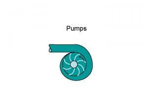
HOW DOES A CENTRIFUGAL PUMP WORK? Fluid enters the impeller axially through the eye then by centrifugal action or force continues radially and discharges around the entire circumference. The fluid in passing through the impeller receives energy from the vanes giving an increase of pressure and velocity. The kinetic (velocity) energy of the discharging fluid is partly converted to pressure energy by suitable design of impeller vanes and volute casing. 9/18/2020 Mohd. Hanif Dewan, Senior Lecturer, IMA, Bangladesh. 3

9/18/2020 Mohd. Hanif Dewan, Senior Lecturer, IMA, Bangladesh. 4

Centrifugal Pump 9/18/2020 Mohd. Hanif Dewan, Senior Lecturer, IMA, Bangladesh. 5

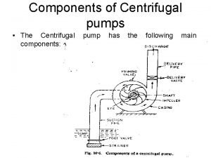
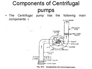
Centrifugal Pump Components 9/18/2020 Mohd. Hanif Dewan, Senior Lecturer, IMA, Bangladesh. 6

Component division A centrifugal pump has two main components: A rotating component comprised of an impeller and a shaft A stationary component comprised of a volute casing, casing cover, and bearings. 9/18/2020 Mohd. Hanif Dewan, Senior Lecturer, IMA, Bangladesh. 7

CENTIFUGAL PUMP 9/18/2020 Mohd. Hanif Dewan, Senior Lecturer, IMA, Bangladesh. 8

9/18/2020 Mohd. Hanif Dewan, Senior Lecturer, IMA, Bangladesh. 9

IMPELLER 1. Impeller serves to convert mechanical energy of the pump into velocity energy of fluid which is pumped continuously 2. The liquid gets the centrifugal force by the rotation of impeller and the liquid from the suction eye continually thrown to the periphery of the impeller. Vanes of Impeller Vane is blades of the impeller as a place of passage of fluid in the impeller. The Eye of Impeller The eye of impeller is the entrance side of suction direction of impeller. 9/18/2020 Mohd. Hanif Dewan, Senior Lecturer, IMA, Bangladesh. 10

Impellers of pumps are classified based on the number of points that the liquid can enter the impeller and also on the amount of webbing between the impeller blades. Impellers can be either single- suction or double-suction. A single-suction impeller allows liquid to enter the center of the blades from only one direction. A double-suction impeller allows liquid to enter the center of the impeller blades from both sides simultaneously giving twice the discharge at a given head. . 9/18/2020 Mohd. Hanif Dewan, Senior Lecturer, IMA, Bangladesh. 11

9/18/2020 Mohd. Hanif Dewan, Senior Lecturer, IMA, Bangladesh. 12

9/18/2020 Mohd. Hanif Dewan, Senior Lecturer, IMA, Bangladesh. 13

Impellers designs can be Open, Semi-open, Enclosed. The open impeller consists only of blades attached to a hub. The semi-open impeller is constructed with a circular plate (the web) attached to one side of the blades. The enclosed impeller has circular plates attached to both sides of the blades are also referred to as shrouded impellers. 9/18/2020 Mohd. Hanif Dewan, Senior Lecturer, IMA, Bangladesh. 14

Open 9/18/2020 Semi-open Mohd. Hanif Dewan, Senior Lecturer, IMA, Bangladesh. Shrouded 15

Open design The vanes are attached to the hub. There is no shroud to support the vanes. These are good designs for pumping stringy materials such as paper stock. Pump efficiency is maintained by setting a close clearance between the impeller vanes and the volute or back plate. Since there is no shroud to strengthen the vanes, their use is often limited to small inexpensive pumps Semiopen design The vanes are attached to the hub with a shroud on one side of the impeller. The pump efficiency is maintained by setting a close clearance between the vanes and the volute or back-plate. Some of these semi-open impellers have pump out vanes on the back of the shroud that reduce the pressure on the back of the shroud and prevent foreign matter from lodging in back of the impeller, interfering with its operation. Closed design In this design the vanes are attached to the hub with a shroud on either side of the impeller. These designs maintain pump efficiency by the use of close clearance wear rings. Closed impellers are sensitive to clogging with solids so their use is limited to the pumping of reasonably clear liquids. Oil refineries use closed impellers because of the problem of maintaining a close tolerance between a semi-open impeller and the pump volute. Explosive products would ignite if the impeller came into contact with the volute, but in the closed impeller version soft wear rings would make the contact. 9/18/2020 Mohd. Hanif Dewan, Senior Lecturer, IMA, Bangladesh. 16

DIFFUSER In some pumps, diffusers are used. These consist of a floating ring of stationary guide vanes surrounding the impeller. The purpose of the diffuser is to increase the efficiency of the centrifugal pump by allowing a more gradual expansion and less turbulent area for the liquid to reduce in velocity. The diffuser vanes are designed in a manner that the liquid exiting the impeller will encounter an ever- increasing flow area as it passes through the diffuser. This increase in flow area causes a reduction in flow velocity, converting kinetic energy into flow pressure. 9/18/2020 Mohd. Hanif Dewan, Senior Lecturer, IMA, Bangladesh. 17

9/18/2020 Mohd. Hanif Dewan, Senior Lecturer, IMA, Bangladesh. 18

VOLUTE CASING The volute casing is like a divergent nozzle which is wrapped around the impeller and serves two main functions (1) It enables velocity energy to be converted into pressure energy, the degree of conversion is governed mainly by the degree of divergence (2) It accommodates the gradual increase in quantity of fluid that builds at discharge from the circumference of the impeller. 9/18/2020 Mohd. Hanif Dewan, Senior Lecturer, IMA, Bangladesh. 19

For the velocity to be constant the volute is made so that cross sectional pipe area increases uniformly from cutwater to throat. With an impeller having six vanes than the cross sectional area of volute at first vane will be 1/6 th of the throat area as one vane is pumping 1/6 th of water quantity, similarly 1/3 rd at second vane and so on, taking vanes in turn from cut water to throat. If the discharge line were chocked or blocked then the pump would merely churn water so the fitting of relief valve is not essential. 9/18/2020 Mohd. Hanif Dewan, Senior Lecturer, IMA, Bangladesh. 20

Pumps of this type are called double volute pumps (they may also be referred to a split volute pumps). In some applications the double volute minimizes radial forces imparted to the shaft and bearings due to imbalances in the pressure around the impeller. 9/18/2020 Mohd. Hanif Dewan, Senior Lecturer, IMA, Bangladesh. 21

Volute casing 9/18/2020 Mohd. Hanif Dewan, Senior Lecturer, IMA, Bangladesh. 22

Shaft serves to continue the torque from the drive during operation and the seat of the impeller and other rotating parts. - Shaft is to transmit the torques, - Support the impeller and other rotating parts, - Minimum clearance between the rotating and stationary parts Loads involved are: - Torque, - Weight of the parts, and - Both the radial and axial hydraulic forces. Shaft sleeve serves to protect the shaft from erosion, corrosion and wear of the stuffing box. In multi-stage pump can be as leakage joint, internal bearings and inter stage or Mohd. Hanif Dewan, Senior Lecturer, IMA, distance sleeve. 9/18/2020 Bangladesh. 23

9/18/2020 Mohd. Hanif Dewan, Senior Lecturer, IMA, Bangladesh. 24

Wearing Rings Centrifugal pumps contain rotating impellers within stationary pump casings. To allow the impeller to rotate freely within the pump casing, a small clearance is designed to be maintained between the impeller and the pump casing. To maximize the efficiency of a centrifugal pump, it is necessary to minimize the amount of liquid leaking through this clearance from the high pressure or discharge side of the pump back to the low pressure or suction side 9/18/2020 Mohd. Hanif Dewan, Senior Lecturer, IMA, Bangladesh. 25

Some wear or erosion will occur at the point where the impeller and the pump casing nearly come into contact. This wear is due to the erosion caused by liquid leaking through this tight clearance and other causes. As wear occurs, the clearances become larger and the rate of leakage increases. Eventually, the leakage could become unacceptably large and maintenance would be required on the pump 9/18/2020 Mohd. Hanif Dewan, Senior Lecturer, IMA, Bangladesh. 26

To minimize the cost of pump maintenance, many centrifugal pumps are designed with wearings which are replaceable rings that attached to the impeller and/or the pump casing to allow a small running clearance between the impeller and the pump casing without causing wear of the actual impeller or pump casing material. These wearings are designed to be replaced periodically during the life of a pump and prevent the more costly replacement of the impeller or the Mohd. Hanif Dewan, Senior Lecturer, IMA, casing. 9/18/2020 Bangladesh. 27

Stuffing Box In almost all centrifugal pumps, the rotating shaft that drives the impeller penetrates the pressure boundary of the pump casing. It is important that the pump is designed properly to control the amount of liquid that leaks along the shaft at the point that the shaft penetrates the pump casing. Factors considered when choosing a method include the pressure and temperature of the fluid being pumped, the size of the pump, and the chemical and physical characteristics of the fluid being pumped. 9/18/2020 Mohd. Hanif Dewan, Senior Lecturer, IMA, Bangladesh. 28

One of the simplest types of shaft seal is the stuffing box which is cylindrical space in the pump casing surrounding the shaft. Rings of packing material are placed in this space to form a seal to control the rate of leakage along the shaft. The packing rings are held in place by a gland which is in turn, held in place by studs with adjusting nuts. As the adjusting nuts are tightened, they move the gland in and compress the packing. This axial compression causes the packing to expand radially, forming a tight seal between Mohd. Hanif Dewan, Senior Lecturer, IMA, the rotating shaft and the inside wall of the 9/18/2020 Bangladesh. 29

The high speed rotation of the shaft generates a significant amount of heat as it rubs against the packing rings. If no lubrication and cooling are provided to the packing, the temperature of the packing increases to the point where damage occurs to the packing, the pump shaft, and possibly nearby pump bearings. Stuffing boxes are normally designed to allow a small amount of controlled leakage along the shaft to provide lubrication and cooling to the packing. The leakage rate can be adjusted by tightening and loosening the packing gland. Mohd. Hanif Dewan, Senior Lecturer, IMA, 9/18/2020 Bangladesh. 30

Gland Packing 9/18/2020 Mohd. Hanif Dewan, Senior Lecturer, IMA, Bangladesh. 31

Mechanical Seals 9/18/2020 Mohd. Hanif Dewan, Senior Lecturer, IMA, Bangladesh. 32

Lantern Ring It is not always possible to use a standard stuffing box to seal the shaft of a centrifugal pump. The pump suction may be under a vacuum so that outward leakage is impossible or the fluid may be too hot to provide adequate cooling of the packing. These conditions require a modification to the standard stuffing box. One method of adequately cooling the packing under these conditions is to include a lantern ring 9/18/2020 Mohd. Hanif Dewan, Senior Lecturer, IMA, Bangladesh. 33

A lantern ring is a perforated hollow ring located near the center of the packing box that receives relatively cool, clean liquid from either the discharge of the pump or from an external source and distributes the liquid uniformly around the shaft to provide lubrication and cooling. The fluid entering the lantern ring can cool the shaft and packing, lubricate the packing, or seal the joint between the shaft and packing against leakage of air into the pump in the event the pump suction pressure is less than that of the atmosphere. 9/18/2020 Mohd. Hanif Dewan, Senior Lecturer, IMA, Bangladesh. 34

“Balancing Holes” 9/18/2020 Mohd. Hanif Dewan, Senior Lecturer, IMA, Bangladesh. 35

BALANCING HOLES IN IMPELLERS The impeller sometimes contains balancing holes that connect the space around the hub to the suction side of the impeller. The balancing holes have a total crosssectional area that is considerably greater than the cross-sectional area of the annular space between the wearing and the hub. The result is suction pressure on both sides of the impeller hub, which maintains a hydraulic balance of axial thrust. 9/18/2020 Mohd. Hanif Dewan, Senior Lecturer, IMA, Bangladesh. 36

Centrifugal Pump Classification by Flow The manner in which fluid flows through the pump is determined by the design of the pump casing and the impeller. The three types of flow through a centrifugal pump are Radial flow, Axial flow, Mixed flow. 9/18/2020 Mohd. Hanif Dewan, Senior Lecturer, IMA, Bangladesh. 37

Radial Flow Pumps In a radial flow pump, the liquid enters at the center of the impeller and is directed out along the impeller blades in a direction at right angles to the pump shaft. The impeller of a typical radial flow pump and the flow through a radial flow pump are shown in Figure 9/18/2020 Mohd. Hanif Dewan, Senior Lecturer, IMA, Bangladesh. 38

9/18/2020 Radial Flow Centrifugal Pump Mohd. Hanif Dewan, Senior Lecturer, IMA, Bangladesh. 39

Axial Flow Pumps In an axial flow pump, the impeller pushes the liquid in a direction parallel to the pump shaft. Axial flow pumps are sometimes called propeller pumps because they operate essentially the same as the propeller of a boat. The impeller of a typical axial flow pump and the flow through a radial flow pump are shown in Figure 9/18/2020 Mohd. Hanif Dewan, Senior Lecturer, IMA, Bangladesh. 40

Axial Flow Centrifugal Pump 9/18/2020 Mohd. Hanif Dewan, Senior Lecturer, IMA, Bangladesh. 41

Mixed Flow Pumps Mixed flow pumps borrow characteristics from both radial flow and axial flow pumps. As liquid flows through the impeller of a mixed flow pump, the impeller blades push the liquid out away from the pump shaft and to the pump suction at an angle greater than 90 o. The impeller of a typical mixed flow pump and the flow through a mixed flow pump are shown in Figure 9/18/2020 Mohd. Hanif Dewan, Senior Lecturer, IMA, Bangladesh. 42

Mixed Flow Centrifugal Pump 9/18/2020 Mohd. Hanif Dewan, Senior Lecturer, IMA, Bangladesh. 43

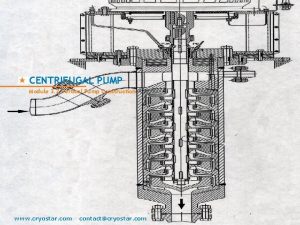
Multi-stages Centrifugal Pump A pump stage is defined as that portion of a centrifugal pump consisting of one impeller and its associated components. Most centrifugal pumps are single-stage pumps, containing only one impeller. A pump containing seven impellers within a single casing would be referred to as a seven-stage pump or generally considered as a multi-stage pump. 9/18/2020 Mohd. Hanif Dewan, Senior Lecturer, IMA, Bangladesh. 44

A centrifugal pump with a single impeller that can develop a differential pressure of more than 150 psid between the suction and the discharge is difficult and costly to design and construct. A more economical approach to developing high pressures with a single centrifugal pump is to include multiple impellers on a common shaft within the same pump casing at moderate speed. Internal channels in the pump casing route the discharge of one impeller to the suction of another impeller 9/18/2020 Mohd. Hanif Dewan, Senior Lecturer, IMA, Bangladesh. 45

The water enters the pump from the top left and passes through each of the four impellers in series, going from left to right. The water goes from the volute surrounding the discharge of one impeller to the suction of the next impeller. 9/18/2020 Mohd. Hanif Dewan, Senior Lecturer, IMA, Bangladesh. 46

Multi-Stage Centrifugal Pump 9/18/2020 Mohd. Hanif Dewan, Senior Lecturer, IMA, Bangladesh. 47

PRIMING OF CENTRIFUGAL PUMPS Centrifugal force does not act on the air. So, if there is air in the system, it will make problem for the operation of a centrifugal pump. The procedure to remove the air from a system is called the priming. All centrifugal pumps are NOT self priming pumps, and therefore for them to function properly they have to be primed. A centrifugal pump is said to be primed when the waterways of the pump are full with the liquid. When first put into service, the waterways are filled with air. If the suction supply is above atmospheric pressure that is the suction head is positive, then this air will be trapped in the pump and form an air lock. The only way to get rid of it by opening a vent valve and releasing it. If on the other hand the suction is negative or below atmospheric then priming can be accomplished by using a foot valve in the suction line and using some form of vacuum-producing device. 9/18/2020 48

WET VACUUM PUMPS (ROTARY AIR PUMP OR WATER RING TYPE AIR PUMP) This pump consists of a circular bladed rotor with forward swept vanes, fitted on the pump spindle and rotating in an elliptical casing. Outside this casing is a reservoir containing fresh water with gravity feed. 9/18/2020 Mohd. Hanif Dewan, Senior Lecturer, IMA, Bangladesh. 49

When the rotor rotates concentric to the axis the water in the casing is driven to the outside of the ellipse. This water therefore recedes from and approaches the centre twice per revolution, producing in effect a series of reciprocating water pistons between the vanes. There are two suction and two discharge ports set in a plate which is adjustable for running clearances. The suction ports are connected to a point near the impeller suction eye by means of a pipe. When the centrifugal pump is started this rotary air pump also starts as it is mounted on the same shaft. 9/18/2020 Mohd. Hanif Dewan, Senior Lecturer, IMA, Bangladesh. 50

As the revolving rotar of the air pump rotates it sucks up the air which is in the suction line and exhausts it to the atmosphere. Soon it starts sucking the water. When the water reaches the centrifugal pump and the rotary air pump, the suction line to the later is cut off by means of a ball float valve. The reservoir has a cooling coil as shown through which passes sea water and this cools the fresh water which gets heated due to the churning action of the air pump impeller. 9/18/2020 Mohd. Hanif Dewan, Senior Lecturer, IMA, Bangladesh. 51

CENTRAL PRIMING SYSTEM The rotary air pump or the water ring pump has to be mounted of the main centrifugal pump on the ship we have to have a separate air pump. This would be an expensive affair and also would require a lot of maintenance. To avoid all this they have come out with a system which is known as the central priming system. It consists of two rotary air pumps mounted on a tank containing fresh water. One pump could be used for service and the other kept on stand by or both could work together in the event of heavy duty. 9/18/2020 Mohd. Hanif Dewan, Senior Lecturer, IMA, Bangladesh. 52

9/18/2020 Mohd. Hanif Dewan, Senior Lecturer, IMA, Bangladesh. 53

• The pumps start automatically through vacuum switches connected to a central vacuum tank, which serves all centrifugal pumps requiring priming. The rotary air pumps work and maintain a hundred percent vacuum in the vacuum tank all the time. When any centrifugal pump has to be primed the respective cock or S. D. N. R. valve is opened and the priming achieved. The advantage of this system are : - 1. Lower initial cost 2. Saving in total horse power 3. Easier maintenance 4. Takes case of minor leaks that may be present in the suction side 5. Very effective 6. Easy to operate. Mohd. Hanif Dewan, Senior Lecturer, IMA, 9/18/2020 Bangladesh. 54

Centrifugal Pump Performance Curve A centrifugal pump uses the conservation of energy principle. It changes velocity energy into pressure energy . As the differential head (H) increases , the flow rate (Q)decreases. The performance curve looks like this. 9/18/2020 Mohd. Hanif Dewan, Senior Lecturer, IMA, Bangladesh. 55

Losses due to Friction A centrifugal pump incurs head losses due to friction. The friction is caused by the fluid changing direction when travelling through the pump and by clearances within the pump. These losses vary with both head and flow. 9/18/2020 Mohd. Hanif Dewan, Senior Lecturer, IMA, Bangladesh. 56

Actual performance curve Subtracting the losses from the ideal gives the actual performance curve for the pump. Ideal Head –Losses =Actual Head It is possible to determine the useful power of a pump by the Mohd. Hanif Dewan, Senior Lecturer, IMA, formula 9/18/2020 Bangladesh. 57

Losses in a centrifugal pump For a centrifugal pump, as previously mentioned , losses vary with pump flow and developed head. This means that the useful power varies. A more useful curve is obtained from plotting Efficiency. Flow. 9/18/2020 Mohd. Hanif Dewan, Senior Lecturer, IMA, Bangladesh. 58

NPSH 9/18/2020 If you start a pump, submerged in water like the sketch indicates, the pump will have a specific capacity at a specific delivery head. If you gradually lift the pump, the pump will, at a specific height, have a perceptible reduction in the capacity. When this occurs, the height of the pump above liquid level is called Net Positive Suction Head or NPSH. The pump suction capabilities are measured by NPSH Mohd. Hanif Dewan, Senior Lecturer, IMA, Bangladesh. 59

Friction Head & NPSHA 9/18/2020 Net Positive Suction Head Available is by NPSHA in short. The static suction head (H) can be positive if the suction is above the pump. The friction head (Hf) varies with the rate of liquid flow. NPSHA is determined by the pump work Mohd. Hanif Dewan, Senior Lecturer, IMA, conditions. Bangladesh. 60

NPSHR & NPSHA Net positive suction head requirement is NPSHR in short For a given rate of flow a pump will have a NPSHR, which is determined by the manufacture. NPSHR varies with liquid flow. 9/18/2020 Mohd. Hanif Dewan, Senior Lecturer, IMA, Bangladesh. 61

CAVITATION Cavitation is derived from the word “Cavity” an empty space or a hollow space. It is caused by the “boiling off” of a liquid at normal temperature and low pressure. It is accentuated (hightened) by the presence of dissolved air which is released when pressure are reduced. If a liquid contains much dissolved air, then as the pressure is reduced (which happens when the pump sucks) the air comes out of solution and forms cavities or bubbles. 9/18/2020 Mohd. Hanif Dewan, Senior Lecturer, IMA, Bangladesh. 62

Each cavitation bubble grows from a nucleus to a finite size and is carried by the flowing liquid into a region of higher pressure which is the vanes of an impeller. Here these bubbles condense and burst or collapse. Condensation takes place violently and character of water hammering and also a rise in temperature. Bubbles follow each other very rapidly and the bursting results in shockwaves which attack the metal causing cavitation pittings in the least resistant places. Erosion due to cavitation is a major problem and is accentuated in high velocity situations. 9/18/2020 Mohd. Hanif Dewan, Senior Lecturer, IMA, Bangladesh. 63

Cavitation 9/18/2020 If the pump operates to the right of point A, then the required suction head is greater than the available suction head. This means that vapour bubbles will occur in the suction pipe. As the vapour bubbles move through the pump, the pressure will increase and the bubble will collapse. This process is called Cavitation and can cause severe damage to the pump. Operation to the left of point A means that vapour bubbles will not form, and so Caviation will not be a problem. Mohd. Hanif Dewan, Senior Lecturer, IMA, Bangladesh. 64

Generally cavitation is favoured under the following circumstances: 1. If the pump has to suck from a great distance that is if the suction head is too great. (NPSHR>NPSHA that might occur during ballast conditions). 2. If the normal discharge rate has been exceeded that is the pump speed has been increased above rated. 3. Improper shape of pump entry passages, or due to certain obstructions in the inlet side. 4. When pump is handling liquids with low vapour pressures such as LPG and LNG. 9/18/2020 Mohd. Hanif Dewan, Senior Lecturer, IMA, Bangladesh. 65

Effects of cavitation area 1. The metal gets eroded and is seen as small pittings. The rate of erosion may be accentuated if the liquid itself has corrosive tendencies. 2. Audible rattling or cracking sounds may be heard which can reach a pitch of dangerous vibrations. 3. Due to the flow disturbances set up the entire performance of the machine may deteriorate – e. g. the head and efficiency of the pump may fall below acceptable value. 9/18/2020 Mohd. Hanif Dewan, Senior Lecturer, IMA, Bangladesh. 66

9/18/2020 Mohd. Hanif Dewan, Senior Lecturer, IMA, Bangladesh. 67

Regions attacked by cavitation area: 1. At the starting stage the collapse of bubbles terminates within the impeller passages. 2. In the fully developed stage the main part of vapour bubble collapse is in the impeller itself and the rest is carried out of the impeller into the diffuser ring and the volute casing, and sometimes even to the next stage of the pump. 9/18/2020 Mohd. Hanif Dewan, Senior Lecturer, IMA, Bangladesh. 68

How a centrifugal pump works: 9/18/2020 Mohd. Hanif Dewan, Senior Lecturer, IMA, Bangladesh. 69

Any question? Thank you! 9/18/2020 Mohd. Hanif Dewan, Senior Lecturer, IMA, Bangladesh. 70
 Lecturer's name
 Mohd ridzal bin mohd sheriff
 Reciprocating pump classification
 Denis papin centrifugal pump
 Axial flow pump example
 Work absorbing device
 Radial flow centrifugal pump
 Carol sution
 Centrifugal pump testing
 Classification of centrifugal pump
 Affinity laws
 Structure of centrifugal pump
 Centrifugalpump
 Centrifugal pump failure modes
 Radial flow centrifugal pump
 Disadvantage of centrifugal pump
 Radial flow centrifugal pump
 Centrifugal pump working principle
 Centrifugal pump training
 Pump in fluid mechanics
 Vehicle mounted pumps
 Barrel chest
 Perusahaan tas hanif membuat 2 macam tas
 Hanif khalak
 Hanif nur widhiyanti
 Hanif nur widhiyanti
 Internal external gear
 Three screw pump
 Designation of lecturer
 140000/120
 Photography lecturer
 Physician associate lecturer
 Lecturer asad ali
 Guest lecturer in geography
 Lector vs lecturer
 Lecturer in charge
 Spe distinguished lecturer
 Lecturer name
 Lecturer in charge
 Designation lecturer
 Pearson lecturer resources
 Good morning students
 Cfa lecturer handbook
 Nazari ismail
 Wan mohd faizal
 Mohd talib latif
 Prof mohd faiz
 I am a bird by kathrina
 Norizan mohd noor
 Syahid mohd zain
 Putra mohd aidil rizal
 Armyn fahmy mohd fahmy
 Kesang leasing sdn bhd v mohd yusof bin ismail
 Ahmad israiwa
 Fitrah manusia
 Maksud strata kamus dewan
 Dewan tanvir ahmed
 Dewan pustaka kuching
 Negara q
 Dewan tanvir ahmed
 Dewan taklimat serdang
 Matlamat pembinaan jalan raya di rom
 Prasun dewan
 Pencegahan kecederaan
 Prasun dewan
 Dewan satuan pandu berfungsi untuk
 Definisi permainan tradisional menurut kamus dewan
 Perbandingan kata adjektif
 Dewan tanvir ahmed
 Jenis plagiat
 Pembaharuan dalam bidang ketenteraan kerajaan abbasiyah


