CEN 4010 Class 4 0908 Introduction to Unified


- Slides: 18

CEN 4010 Class 4 – 09/08 Introduction to Unified Modeling Language (UML) • • • Review - Class 4 Overview of UML Diagrams – – – use case class sequence Note: See example the course home page. CENuse 4010 case Class on 4 - 09/08

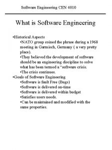
Overview of UML • UML is a notation unifying – OMT (Object Modeling Technique – Rumbaugh et al, 1991), – Booch (Booch, 1994), and – OOSE (Object-Oriented Software Engineering – Jacobson et al. 1992). • The Unified Modeling Language (UML) is a standard language for writing software blueprints. The UML maybe used to visualize, specify, construct, and document the artifacts of a software-intensive system. (Booch et al. 1999) CEN 4010 Class 4 - 09/08 2

Overview of UML cont • UML is appropriate for modeling systems ranging from enterprise information systems to distributed Web-based applications and even to hard real time embedded systems. • UML is very expressive. • UML is a language for: – – Visualizing Specifying Constructing Documenting CEN 4010 Class 4 - 09/08 3

Overview of UML cont • Language – provides a vocabulary and rules for combining words in the vocabulary for the purpose of communication. • Visualizing – each symbol in the UML notation represents well defined semantics. UML can represent models unambiguously. • Specifying – UML is used to specify models i. e. , build models that are precise, unambiguous, and complete. CEN 4010 Class 4 - 09/08 4

Overview of UML cont • Constructing – UML models can be mapped to entities in programming languages (PLs) e. g. , C++, Java, or Visual Basic. Note, entities in PLs can also be reverse engineered to produce UML models. • Documenting – UML can be used to document artifacts produced at each stage of the software process. For example, use case diagrams during requirements analysis. CEN 4010 Class 4 - 09/08 5

Overview of UML cont • Building blocks of UML 1. Things 2. Relationships 3. Diagrams • There are four kinds of things in UML: 1. 2. 3. 4. Structural Behavioral Grouping Annotational CEN 4010 Class 4 - 09/08 6

Overview of UML cont • Structural – the nouns of UML models e. g. , a class. • Behavioral – dynamic parts of UML i. e. , the verbs of the model representing behavior over time and space. • Grouping – the organizational parts of UML models e. g. , packages, namespaces. • Annotational – explanatory parts of UML models e. g. , a note. CEN 4010 Class 4 - 09/08 7

Overview of UML cont • There are four kinds of relationships in UML: 1. 2. 3. 4. • • Dependency Association Generalization Realization Dependency (between two things) – a change to one thing may affect the semantics of the other thing. Association – describes links i. e. , a connection among objects. CEN 4010 Class 4 - 09/08 8

Overview of UML cont • • Generalization (specialization/generalization) – objects of a specialized element (the child) are substitutable for objects of the generalized element (the parent). Realization – a semantic relationship between classifiers, i. e. , a classifier (interface) specifies a contract to be carried out by another classifier (class). CEN 4010 Class 4 - 09/08 9

Diagrams in UML • A diagram is a graphical representation of a set of elements, most often rendered as a connected graph of vertices (things) and arcs (relationships). • Diagrams in UML – Class – Object – Component – Deployment Static view of system CEN 4010 Class 4 - 09/08 10

Diagrams in UML cont • Diagrams in UML cont – – – Use case Sequence Collaboration Statechart Activity Dynamic view of system • A use case diagram shows a set of use cases and actors (a special kind of class) and their relationships. • Recall, a use case describes a function provided by the system from an external point of view. CEN 4010 Class 4 - 09/08 11

Example of Use Case Diagram Simple. Watch. User Read. Time Set. Time Watch. Repair. Person Use case diagram describing the functionality of a simple watch. Change. Battery CEN 4010 Class 4 - 09/08 12

Use Case Diagram cont. • The identification of actors and use cases results in the definition of the boundary of the system i. e. , identify tasks accomplished by system and tasks accomplished by environment. • Actors are outside the boundary of the system. • Use cases are inside the boundary of the system. CEN 4010 Class 4 - 09/08 13

Class Diagram • A class diagram describes the system in terms of classes, attributes (data items, instance variables), operations (member functions, methods) and their relationships. • An attribute is a named property of a class that describes a range of values that instances of the property may hold. • An operation is the implementation of a service that can be requested from any object of the class to affect behavior. CEN 4010 Class 4 - 09/08 14

Example of Class Diagram Simple. Watch 1 2 Push. Button Class Structure <class name> <attributes> <operations> 1 Display 1 1 1 2 1 Battery Time Details of the Time class CEN 4010 Class 4 - 09/08 15

Sequence Diagrams • Interaction diagrams – sequence and collaboration diagrams. • An interaction diagram shows an interaction, consisting of a set of objects and their relationships, including the messages that may be dispatched among them. • A sequence diagram is an interaction diagram that emphasizes the time-ordering of messages. CEN 4010 Class 4 - 09/08 16

Example of a Sequence Diagram Set_minutes use case CEN 4010 Class 4 - 09/08 17

UML Tools • Demonstration of Rational Rose • Use Case Stuff CEN 4010 Class 4 - 09/08 18
 Cen 4010
 Cen 4010
 Itec 4010
 Compre dispersantes de pigmentos orgánicos
 Indeks cen industrijskih proizvodov
 Cenacademy
 Cen tc 278
 Wzrost cen stali
 Cen cenelec etsi
 Capelle marnix
 Indeks cen industrijskih proizvodov
 Cen 5016
 Cen 5016
 Cena v marketingu
 Cen 5016
 Indeks cen laspeyresa
 Asociace realitních kanceláří cenová mapa
 Cen usa
 Cén lá atá ann inniu

