CE 6702 PRESTRESSED CONCRETE STRUCTURES UNITI INTRODUCTION THEORY


 are")


:")
: Parabolic and straight tendons:")


- Slides: 43
CE 6702 PRESTRESSED CONCRETE STRUCTURES
UNIT-I INTRODUCTION – THEORY AND BEHAVIOUR
Basic Concepts • A prestressed concrete structure is different from a conventional reinforced concrete structure due to the application of an initial load on the structure prior to its use. • The initial load or ‘prestress’ is applied to enable the structure to counteract the stresses arising during its service period. • Wooden barrel construction by force-fitting of metal bands and shrink-fitting of metal tyres on wooden wheels indicate that the art of prestressing has been practiced from ancient times.
Simple Examples
Advantages • The prestressing of concrete has several advantages as compared to traditional reinforced concrete (RC) 1. Section remains uncracked under service loads • Reduction of steel corrosion – Increase in durability. • Full section is utilised – Higher moment of inertia (higher stiffness) – Less deformations (improved serviceability). • Increase in shear capacity. • Suitable for use in pressure vessels, liquid retaining structures. • Improved performance (resilience) under dynamic and fatigue loading.
2. High span-to-depth ratios • Larger spans possible with prestressing • For the same span, less depth compared to RC member. – Reduction in self weight – More aesthetic appeal due to slender sections – More economical sections. • Typical values of span-to-depth ratios in slabs are given below 3. Suitable for precast construction The advantages of precast construction are as follows. – – – Rapid construction Better quality control Reduced maintenance Suitable for repetitive construction Multiple use of formwork
Materials Required • High-Strength concrete • High tensile steel High Strength concrete: • The minimum 28 days cube compressive strength prescribed in IS: 1343 is 40 N/mm 2 for pre-tensioned members and 30 N/mm 2 for post-tensioned members. • The value of total residual shrinkage strain recommended in IS code for the purpose of design are 3. 0 x 10 -4 for pre-tensioned members and (2. 0 x 10 -4)/log(t+2) for post-tensioned members. • An estimate of the shrinkage of a symmetrically reinforced concrete section may be obtained from the relation
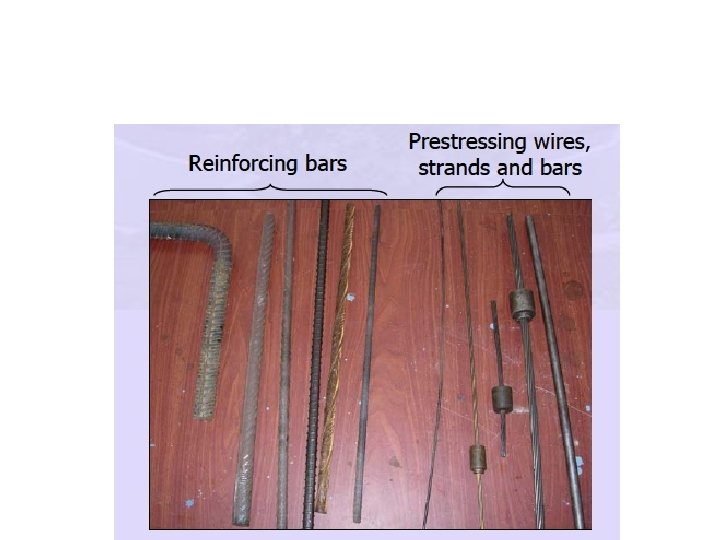
Forms of Prestressing Steel Wires A prestressing wire is a single unit made of steel. The nominal diameters of the wires are 2. 5, 3. 0, 4. 0, 5. 0, 7. 0 and 8. 0 mm. Strands A few wires are spun together in a helical form to form a prestressing strand. Tendons A group of strands or wires are placed together to form a prestressing tendon. Cables A group of tendons form a prestressing cable. The cables are used in bridges. Bars A tendon can be made up of a single steel bar. The diameter of a bar is much larger than that of a wire. Bars are available in the following sizes: 10, 12, 16, 20, 22, 25, 28 and 32 mm.
High Tensile Steel: • The tensile strength of prestressing steel is given in terms of the characteristic tensile strength (fpk). • The high-tensile steel used generally consists of wires, bars or strands. • High tensile steel usually contains 0. 6 -0. 85 per cent carbon. • Nominal size of bars used for prestressing are 10, 12, 16, 20, 22, 25, 28 and 32 mm diameter. • The ultimate tensile strength of different sizes of wires, bars and strands are specified in IS codes
System and Method of Pre-stressing Hydraulic Prestressing This is the simplest type of prestressing, producing large prestressing forces. The hydraulic jack used for the tensioning of tendons, comprises of calibrated pressure gauges which directly indicate the magnitude of force developed during the tensioning. Mechanical Prestressing In this type of prestressing, the devices includes weights with or without lever transmission, geared transmission in conjunction with pulley blocks, screw jacks with or without gear drives and wire-winding machines. This type of prestressing is adopted for mass scale production.
Electrical Prestressing In this type of prestressing, the steel wires are electrically heated anchored before placing concrete in the moulds. This type of prestressing is also known as thermo-electric prestressing. External Prestressing • When the prestressing is achieved by elements located outside the concrete, it is called external prestressing. The tendons can lie outside the member (for example in Igirders or walls) or inside the hollow space of a box girder. This technique is adopted in bridges and strengthening of buildings. In the following figure, the box girder of a bridge is prestressed with tendons that lie outside the concrete.
Pre-tensioning System • In pre-tensioning system, the high-strength steel tendons are pulled between two end abutments (also called bulkheads) prior to the casting of concrete. • The various stages of the pre-tensioning operation are summarised as follows. – Anchoring of tendons against the end abutments – Placing of jacks – Applying tension to the tendons – Casting of concrete – Cutting of the tendons.
Stages of Pre-tensioning
Post-tensioning systems • In post-tensioning systems, the ducts for the tendons (or strands) are placed along with the reinforcement before the casting of concrete. The tendons are placed in the ducts after the casting of concrete. • The various stages of the post-tensioning operation are summarised as follows. – – – Casting of concrete. Placement of the tendons. Placement of the anchorage block and jack. Applying tension to the tendons. Seating of the wedges. Cutting of the tendons.
Stages of Post-tensioning
Analysis of section • • Analysis at Transfer Analysis at Service Loads Analysis of Ultimate Strength Analysis of Behaviour • The analysis of members refers to the evaluation of the following. – Permissible prestress based on allowable stresses at transfer. – Stresses under service loads. These are compared with allowable stresses under service conditions. – Ultimate strength. This is compared with the demand under factored loads. – The entire axial load versus deformation behaviour.
Stress Concept
Resultant stress at a section • The resultant stresses in concrete at any section are obtained by superposing the effects of prestress and the flexural stress developed due to loads. • The resultant stresses at top and bottom fibres of concrete at any given section are obtained as
Strength Concept
Load carrying Mechanism
Load balancing concept
Effect of loading on the tensile stresses in tendons • The rotation at the supports due to hogging of the beam is obtained by applying Mohr’s theorem
Losses of Prestress • The losses are broadly classified into two groups, – Immediate – Time-dependent. • The immediate losses occur during prestressing of the tendons and the transfer of prestress to the concrete member. • The time-dependent losses occur during the service life of the prestressed member.
Factors affecting the losses
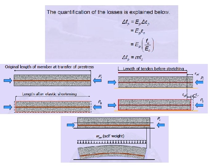
Elastic Shortening • The elastic shortening loss is quantified by the drop in prestress (Δfp) in a tendon due to the change in strain in the tendon (Δεp). • It is assumed that the change in strain in the tendon is equal to the strain in concrete (εc) at the level of the tendon due to the prestressing force. • This assumption is called strain compatibility between concrete and steel. • A linear elastic relationship is used to calculate the strain from the stress.
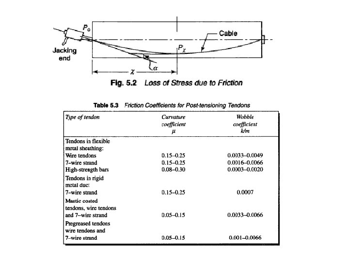
Friction • The friction generated at the interface of concrete and steel during the stretching of a curved tendon in a post -tensioned member, leads to a drop in the prestress along the member from the stretching end. • The loss due to friction does not occur in pre-tensioned members because there is no concrete during the stretching of the tendons. • The friction depends on the following variables. – Coefficient of friction (μ) – Curvature of the tendon (dα) – The amount of prestressing force (P)
Anchorage Slip • The anchorage block also moves before it settles on the concrete. • There is loss of prestress due to the consequent reduction in the length of the tendon. • The total anchorage slip depends on the type of anchorage system. • In absence of manufacturer’s data, the following typical values for some systems can be used.
Creep • Creep of concrete is defined as the increase in deformation with time under constant load. Due to the creep of concrete, the prestress in the tendon is reduced with time. • The ratio of the ultimate creep strain to the elastic strain is defined as the ultimate creep coefficient or simply creep coefficient θ. • The creep coefficient θ is provided for three values of age of loading. • IS: 1343 - 1980 gives guidelines to estimate the ultimate creep strain in Section 5. 2. 5
Shrinkage • Shrinkage of concrete is defined as the contraction due to loss of moisture. • Due to the shrinkage of concrete, the prestress in the tendon is reduced with time. • In special situations detailed calculations may be necessary to monitor shrinkage strain with time. • Specialised literature or international codes can provide guidelines for such calculations.
Relaxation of Steel • Relaxation of steel is defined as the decrease in stress with time under constant strain. • Due to the relaxation of steel, the prestress in the tendon is reduced with time. • The relaxation depends on the type of steel, initial prestress (fpi) and the temperature. • To calculate the drop (or loss) in prestress (Δfp), the recommendations of IS: 1343 - 1980 can be followed in absence of test data.
Deflection of Pre-stressed concrete • Structural concrete members should be designed to have adequate stiffness to limit defections. • Excessive deflection are likely to cause damage to finishes, partitions and associated structures.
Factors influencing deflection • • Imposed load and self-weight Magnitude of the prestressing force Cable profile Second moment of area of cross section Modulus of elasticity of concrete Shrinkage, creep and relaxation of steel stress Span of the member Fixed condition
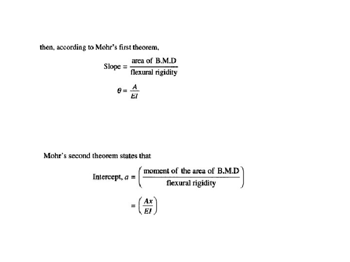
Short term deflection • Short-term deflection of prestressed members are governed by the bending moment distribution along the span and the flexural rigidity of the members. • Mohr’s moment area theorems are readily applicable for the estimation of deflection due to the prestressing force, self-weight and imposed loads.
Effect of tendon profile on deflection • Since the bending moment at every section is the product of the prestressing force and eccentricity, the tendon profile itself will represent the shape of the BMD. Straight Tendons:
Trapezoidal Tendons: Considering the BMD the deflection at the centre of the beam is obtained by taking the moment of area of BMD over one-half of the span. Parabolic Tendons(Central Anchors): The deflection of a beam with parabolic tendons having an eccentricity e at the centre and zero at the supports
Parabolic Tendons(Eccentric anchors):
Sloping Tendons (Eccentric anchorage): Parabolic and straight tendons:
Prediction of Long-term deflection
Thank You