CE 547 Flow Measurement and Screens Flow Meters


 and (2) n n n n V = velocity")


")


")


")
 is")


 Used to remove smaller particles in water treatment plants")
 n n n n n Made of very fine fabric")
 n n P")
 Since, P")

 as it")

- Slides: 66
CE 547 Flow Measurement and Screens
Flow Meters: are devices used to measure the flow rate of a fluid n In Water, all types of flow meters can be used n In Wastewater, the choice is critical due to solid content: n Solids can be removed n Flow has enough energy to be self-cleaning n
Rectangular Weirs Fully-contracted weir
Suppressed weir: weir extends to the channel vertical sides
P = weir height H = head over the weir
The energy equation between (1) and (2) n n n n V = velocity (average) P = pressure y = height above bottom of channel Z = height of bottom above a datum hl = head loss between (1) and (2) g = gravitational constant = specific weight of water
In the figure: Z 1 = Z 2 = 0 V 2 >> V 1 P 1 = P 2 = atmospheric pressure If hl was neglected, then: y 1 = H + P y 2 = yc + P Substitute in the energy equation and change V 2 to Vc (critical velocity)
n Specific energy equation states that: n The critical depth, yc, occurs at minimum specific energy Differentiate E with respect to y and equate to zero Use ( Q = VA ) n n n Q = flow rate V = velocity A = cross-sectional area
A/T = hydraulic depth, D n D is simply equals to yc n
Substitute for yc in: To get:
If L = length of the weir, then and Use
Remember n hl and V 1 were neglected n y 2 was assumed to be (yc = P) n L must be corrected depending upon whether the equation to be used for fully contracted or suppressed weirs
To make the equation more practical For fully contracted weirs
Example
To measure the flow rate of wastewater, a rectangular weir was used. The flow rate is 0. 33 m 3/s. Design the weir. The width of the rectangular channel to be connected to the weir is 2. 0 m and the available head (H) is 0. 2 m. Solution Use a fully suppressed weir and assume length, L = 2. 0 m
Then, the dimensions of the weir are: L = 2. 0 m n P = 0. 6 m n
Triangular Weir (V-notch weir)
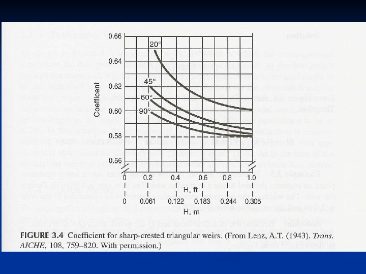
For low flow rates, triangular weirs are more accurate than the rectangular ones. The hydraulic profile in channels measured by triangular weirs is exactly similar to that measured by rectangular weirs K is obtained from the Figure 3. 4 and multiplied by (8/15) as a correction factor.
Example
Solve previous example for v-notch weir if: Q = 0. 33 m 3/s n Channel width = 2. 0 m n H = 0. 2 m n Solution
From Figure 3. 4 at H = 0. 2 m Values of [ K(8/15) tan ( /2) ], in the table, is near 4. 16 For > 90 , K = 0. 58 then, 4. 16 = 0. 58 (8/15) tan ( /2) = 13. 45 so, = 171 K K(8/15) tan ( /2) 90 0. 583 0. 31 60 0. 588 0. 18 45 0. 592 0. 13 20 0. 609 0. 06
Trapezoidal Weirs Flow is contracted in trapezoidal weirs n The equation for suppressed weirs can be used: n n In this case = 28
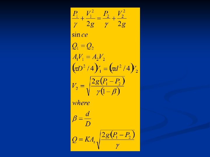
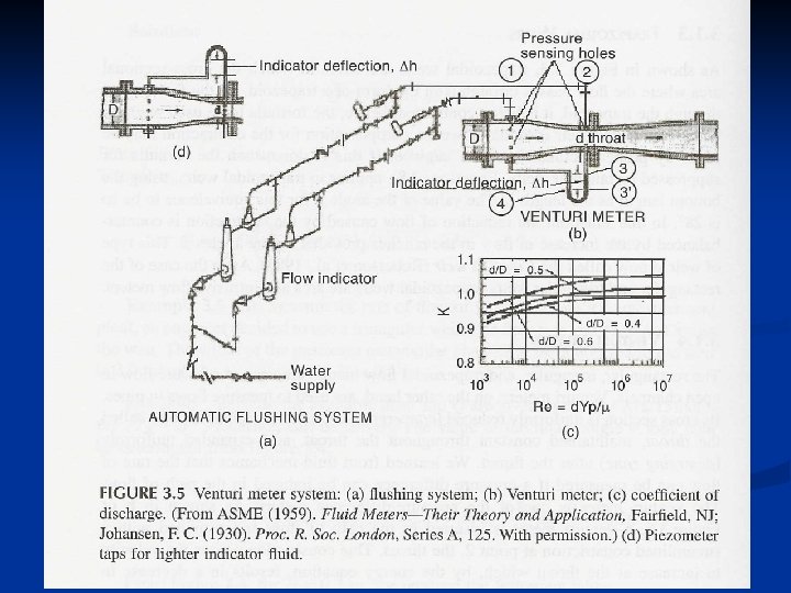
Venturi Meters n Used to measure flow rate in pipes
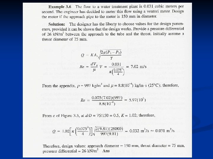
Example
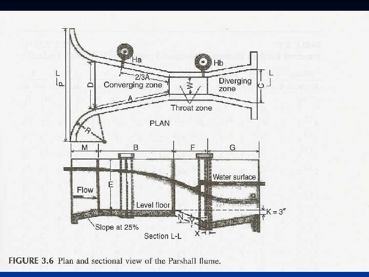
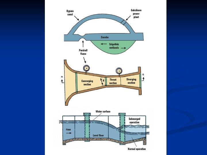
Parshall Flumes
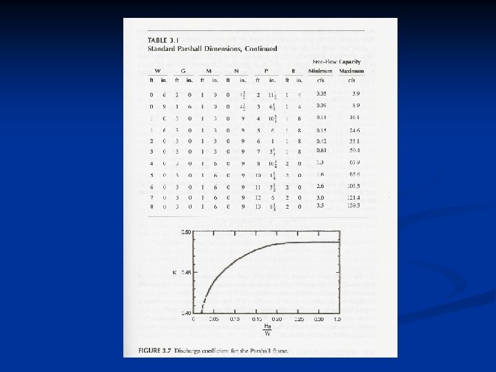
n Can be used with Parshall Flumes n Replace L with W (width of throat) n Replace H with Ha (water surface elevation above flume floor level in the converging zone) Then, K can be obtained from Figure 3. 7. Also Table 3. 1 shows standard Parshall flume dimensions.
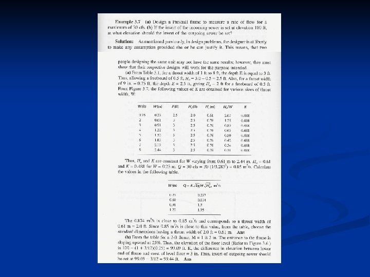
Example
Miscellaneous Flow Meters Magnetic Flow Meter (measures flow by producing magnetic fields)
What is a Magnetic Flow Meter? A magnetic flow meter (magnetic flow meter) is a volumetric flow meter which does not have any moving parts and is ideal for wastewater applications or any dirty liquid which is conductive or water based. Magnetic flow meters will generally not work with hydrocarbons, distilled water and many non-aqueous solutions). Magnetic flow meters are also ideal for applications where low pressure drop and low maintenance are required.
Principle of Operation The operation of a magnetic flowmeter or mag meter is based upon Faraday's Law, which states that the voltage induced across any conductor as it moves at right angles through a magnetic field is proportional to the velocity of that conductor. Faraday's Formula: E is proportional to V B D where: n n E = The voltage generated in a conductor V = The velocity of the conductor B = The magnetic field strength D = The length of the conductor
To apply this principle to flow measurement with a magnetic flowmeter, it is necessary first to state that the fluid being measured must be electrically conductive for the Faraday principle to apply. As applied to the design of magnetic flowmeters, Faraday's Law indicates that signal voltage (E) is dependent on the average liquid velocity (V) the magnetic field strength (B) and the length of the conductor (D) (which in this instance is the distance between the electrodes). In the case of wafer-style magnetic flowmeters, a magnetic field is established throughout the entire cross-section of the flow tube (Figure 1). If this magnetic field is considered as the measuring element of the magnetic flowmeter, it can be seen that the measuring element is exposed to the hydraulic conditions throughout the entire crosssection of the flowmeter. With insertion-style flowmeters, the magnetic field radiates outward from the inserted probe (Figure 2).
Magnetic Meter Selection The key questions which need to be answered before selecting a magnetic flowmeter are: n n n n n Is the fluid conductive or water based? Is the fluid or slurry abrasive? Do you require an integral display or remote display? Do you require an analog output? What is the minimum and maximum flow rate for the flow meter? What is the minimum and maximum process pressure? What is the minimum and maximum process temperature? Is the fluid chemically compatible with the flow meter wetted parts? What is the size of the pipe? Is the pipe always full?
Turbine Flow Meters
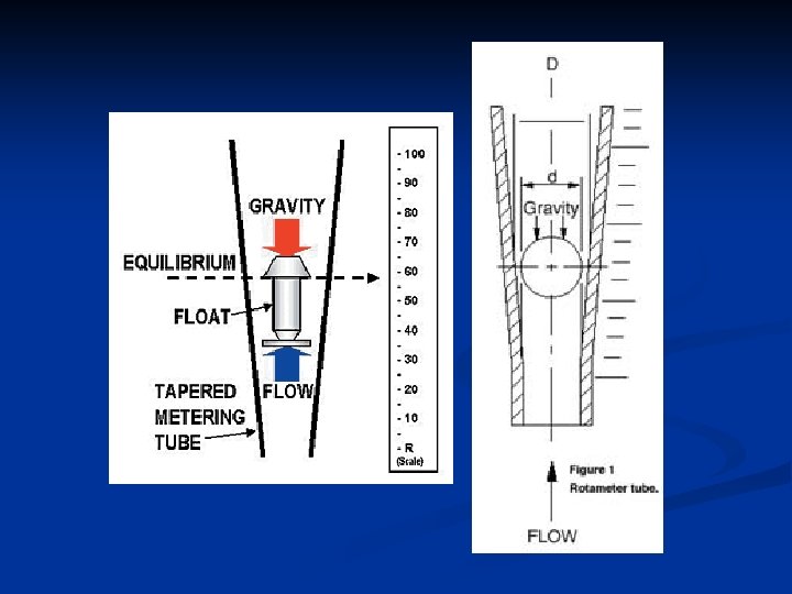
Rotameters or Variable Area Flow Meters Variable area flow meters, or rotameters, use a tube and float to measure flow. As the fluid flows through the tube, the float rises. Equilibrium will be reached when pressure and the buoyancy of the float counterbalance gravity. The float's height in the tube is then used to reference a flow rate on a calibrated measurement reference.
Important Information on Rotameters n n The Variable-Area type flowmeter, or Rotameter, is one of the most economical and reliable of flow measurement instruments. In various configurations it can be designed to withstand high pres sures, corrosive fluids, high temperatures, and is completely independent of factors influencing electronic meters. They can be calibrated to measure nearly any gas or liquid, because their principles of operation are simple and well understood. The flow indication is obtained from a balance of the fluid forces underneath the float with gravity.
Important Information on Rotameters n This is done using a uniformly tapered tube, a float whose diameter is nearly identical to the tube ID at the inlet, and a scale to correlate float height. The flow tube is traditionally placed in a vertical position and fluid enters from the bottom, forcing the float up in the tube until a sufficient annular opening exists between the float and tube to allow the total volume of fluid to flow past the float. At this point the float is in an equilibrium position and its height is proportional to the flow rate.
Important Information on Rotameters n With this in mind, many simple factors influencing rotameter performance are easily understood. For example, increasing the density and weight of the float will require a higher flow rate to force the ball up to any height in the tube. In addition, it is easy to see that any changes in the fluid caused by temperature or pressure will affect the float's position. This is particularly true for gases which are compressible, and are therefore, greatly affected by operating pressures. Studies over the years have resulted in many
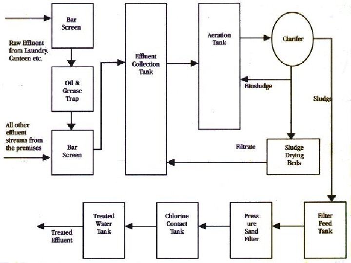
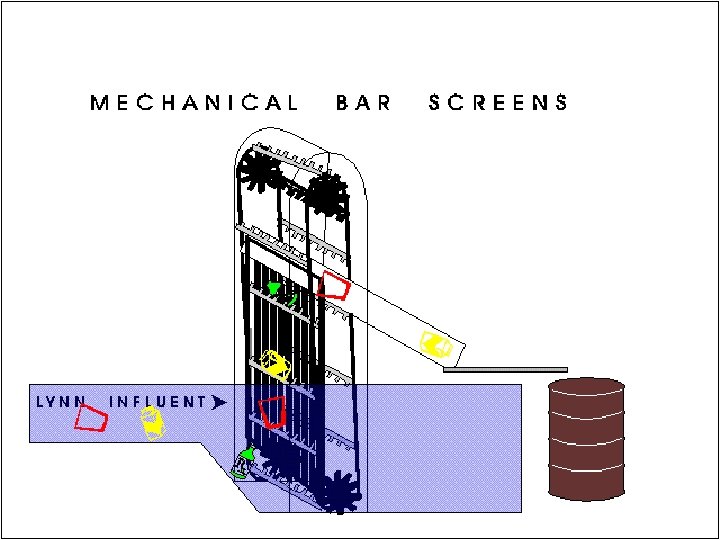
Screening
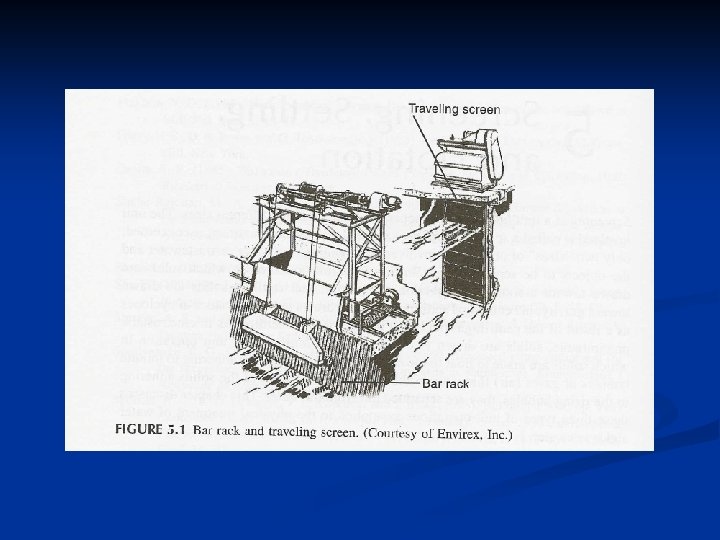
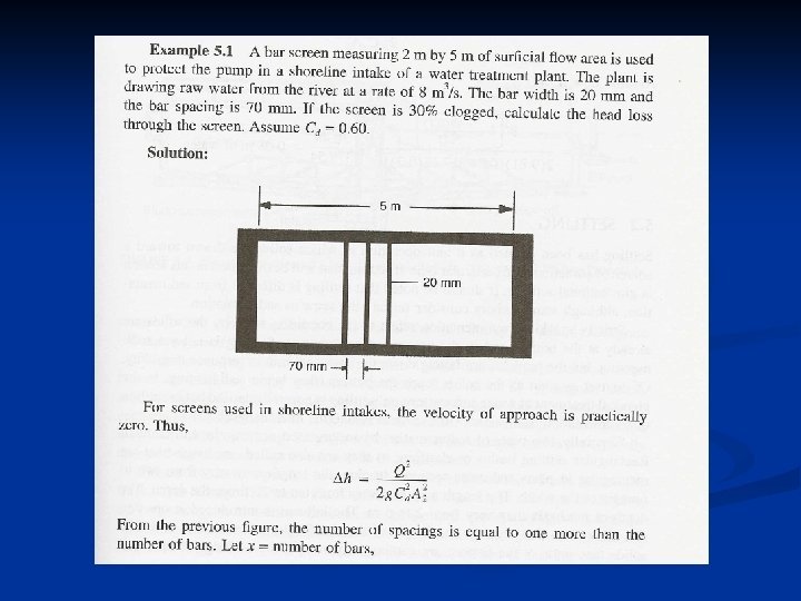
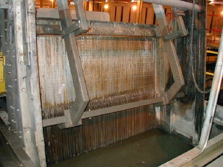
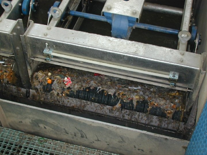
Is a unit operation that separates materials into different sizes using screens Bar Racks or Bar Screen (Fig 5. 1) Are composed of large bars spaced at 25 – 80 mm apart n Used to exclude large particles n Used in water intakes at shores and wastewater treatment plants n Hand cleaned or mechanically cleaned n
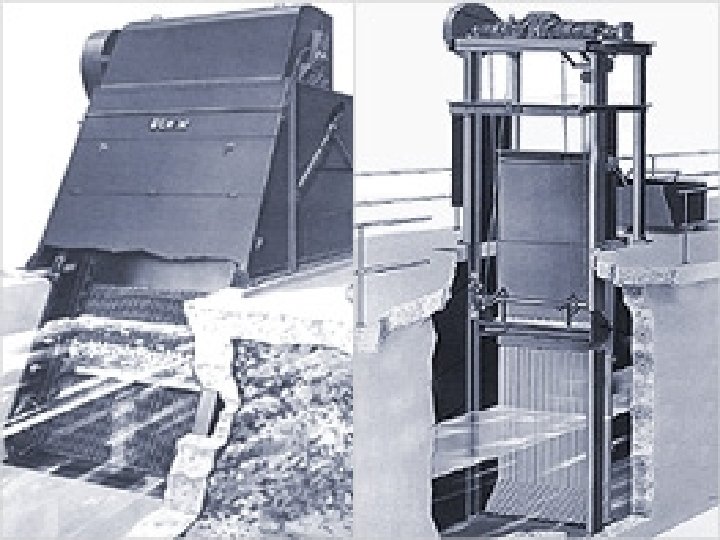
Traveling Screens (Fig 5. 2) Used to remove smaller particles in water treatment plants (following bar screens) such as leaves, small fish and other materials that pass the bar screen.
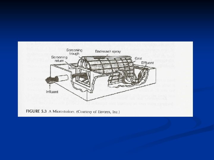
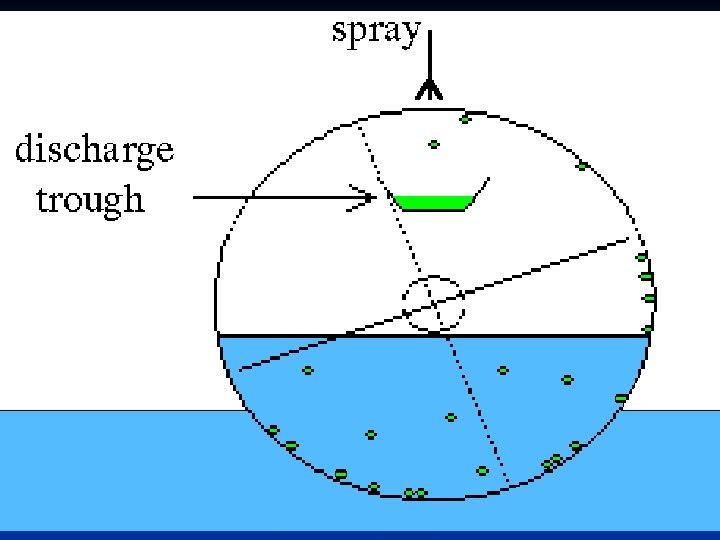
Micro-strainer (Fig 5. 3) n n n n n Made of very fine fabric or screen wound around a drum 75% of the drum is submerged Rotates at 5 to 45 rpm Influent is introduced from the underside of the drum and exits into the outside Strained materials (solids) are retained inside of the drum and removed by jets of water through a trough inside the drum Flow of influent is sometimes from the outside to the inside Used to remove high concentrations of algae (effluent from stabilization ponds) or treatment of effluents from biological treatment processes The pore size of micro-strainers range between 20 – 60 m Material used in micro-strainers include stainless steel and polyester
Head Loss in Bar Racks Apply Bernoulli equation (Fig 5. 2) n n P = pressure V = velocity (V 1 = approach velocity) h = elevation head g = acceleration due to gravity
Approach velocity should be maintained at selfcleaning velocity ( 0. 76 m/s) Since, P 1 = P 2 = atmospheric pressure Then, From continuity equation
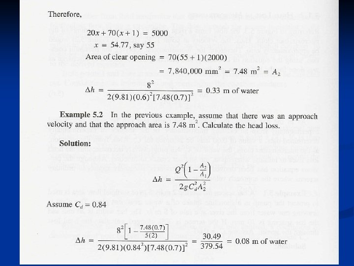
Bernoulli equation assumes frictionless flow, to correct for this, a coefficient of discharge must be added to the equation, thus: Solve for h Cd is determined experimentally or a value of 0. 84 may be used. As the screen clogs, the value of A 2 will decrease.
Head Loss in Micro-strainers The flow turns at right angle (90 ) as it enters the openings of the micro-strainer cloth. Therefore, the approach velocity (V 1) is equal to ZERO. Thus: Similarly, Cd can be determined experimentally or a value of 0. 60 can be used. The above equation can be applied to screens where the approach velocity is negligible.
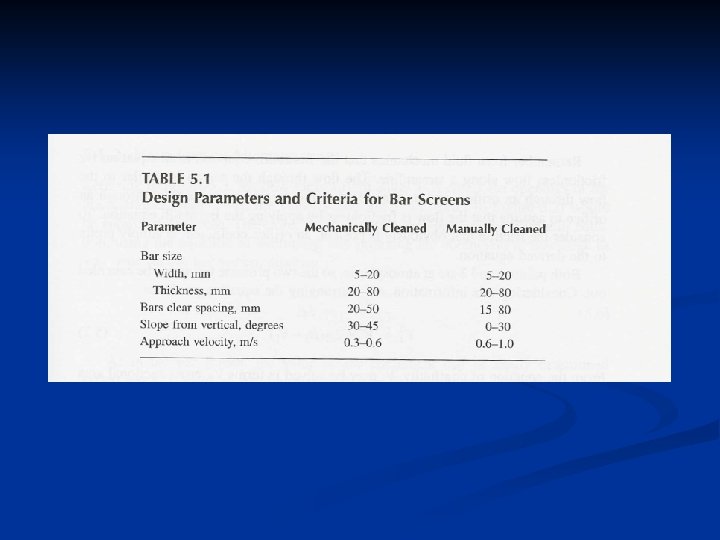
Design Parameters and Criteria for Bar Screens Parameter Mechanically Cleaned Manually Cleaned Bar Size Width, mm Thickness, mm 5 – 20 20 – 80 Bar Clear Spacing, mm 20 – 50 15 – 80 Slope from Vertical, degree 30 – 45 0 – 30 Approach Velocity, m/s 0. 3 – 0. 6 – 1. 0