CE 3372 Water Systems Design Meeting 004 Flow


- Slides: 24

CE 3372 Water Systems Design Meeting 004

Flow in Closed Conduits • Chapter 2, pp 26 -40 – Solutions Exercise Set #003 – Conservation of energy – HGL, EGL – Minor Loss – Non-circular conduit – Alternative head loss formulas

Conservation of Energy • Energy balance: – heat transfer into a system less work done by the system plus internal energy transferred into a system by mass flow into the system is equal to the net increase of internal energy in a system.

Conservation of Energy • Energy balance: – After considerable simplification, the common form of the steady-state energy balance used in liquid flow systems is Friction loss Added head (from a pump) Extracted head (from a turbine)

Conservation of Energy • Momentum balance: – Bernoulli equation and a head loss term related to boundary stresses.

Conservation of Energy • Dimensional analysis and experimental correlations – The engineer must make the experiments to find the structure of the correlation. The Moody chart is the result of such an experimental investigation. Structure of this function is found by experiments and regressions to relate the explanatory variables and the response.

Conservation of Energy • Energy balance: Conduit losses Additional (fittings, junctions, etc. ) losses

Energy Grade Line • The total dynamic head (TDH) at a section of conduit is comprised of pressure, velocity, and elevation head. • A “line” that relates the TDH to location (a profile) is called the energy grade line (EGL)

Hydraulic Grade Line • The total static head at a section of conduit is comprised of pressure, and elevation head. • A “line” that relates the static head to location (a profile) is called the hydraulic grade line (HGL)

Grade Lines • The EGL and HGL are useful to visualize the state of a system at different locations. – The HGL usually remains above the upper boundary of flow (the crown of the pipe); otherwise negative gage pressures can result – these have serious implications for pumping. – The EGL is always above the HGL if liquid is moving.

Minor Loss • Minor loss is the name given to the losses in the energy equation that occur over short distances (minor distances) as compared to the pipeline losses.

Minor Loss • The loss coefficients, K, are determined by experiment, usually reported by manufacturer and tabulated. • Table 2. 7 in Chin is typical

Minor Loss • NCEES supplied reference on page 65.

Entrance and Exit Loss • NCEES supplied reference on page 66

Minor Losses • Minor losses are minor in the context of distance over which loss occurs, but are not minor in magnitude. • These losses are important and the magnitude of loss is at times equivalent to hundreds of feet (meters) of pipe. – This observation is sometimes used in pipeline analysis where fittings are replaced in the analysis by lengths of pipe that produce the equivalent loss. – Equivalent pipe lengths are an analysis trick, and the real fittings still exist (in the real system).

Non-circular conduit • The hydraulic radius (of any flow section) is the ratio of flow area and wetted perimeter. • Non-circular conduits are converted into equivalent circular conduits (for analysis) using the hydraulic radius.

Non-circular conduit • Head loss formula: • Reynolds number:

Empirical Loss Formulas • The loss formula presented so far (Darcy. Weisbach) is based on fluid mechanics principles -- it is empirical in the sense that the friction factors are experimentally derived. • The Hazen-Williams formula is an alternate VALID FOR WATER IN PIPES. HW roughness coefficient (tabulated) Friction slope (slope of EGL)

Empirical Loss Formulas • Hazen-Williams Coefficients

Empirical Loss Formulas • Manning’s formula (usually used on open channels, but sometimes in pipe flow) Friction slope (slope of EGL) Manning’s roughness coefficient (tabulated)

Empirical Loss Formulas • Manning’s coefficients for pipeflow type cases.

Examples • Various to illustrate: – Single pipelines “ 3 classical head-loss problems”. – Energy equation with added head, turbines, and fittings, HGL and EGL. – Non-circular. – Hazen-Williams. – Manning’s.

Readings • Chapter 2, pp 40 – 48 • EPANET Users Manual, pp 1 -26

Exercises • Chin, pp 90 -92 – Problems 2. 9, 2. 16, 2. 19, 2. 20, 2. 22, 2. 23 • Use the Hazen-Williams formula to estimate the head loss in a 1 -foot diameter, 1625 -foot long, new ductile iron pipe. • Use Manning’s formula to estimate the head loss in a 1 -foot diameter, 1625 -foot long, new ductile iron pipe. • Use the Darcy-Weisbach formula to estimate the head loss in a 1 -foot diameter, 1625 -foot long, new ductile iron pipe. – Note that the Hazen-Williams and Manning’s formulas are presented in SI units and the U. S. Customary forms of the formulas must be used! (NCEES supplied reference might help, and there will always be Paris)
 Proxyvo
 Water and water and water water
 Nf p 06-004
 Pyp 004 kfupm
 Auec2-001
 700 004
 Sol
Sol Team-004
 0560 004
 Wer darf behälter freimessen?
 For today's meeting
 Proposal kickoff meeting agenda
 What is meeting and types of meeting
 What is meeting and types of meeting
 Fio2 calculation nasal cannula
 Venturi mask flow rate
 Non rebreather mask definition
 Turbulent flow
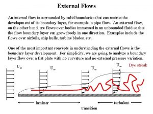
 Internal vs external flow
 Ecological succession
 Flow of energy vs flow of matter
 Structure chart in software engineering
 Transform flow and transaction flow
 Rotational flow and irrotational flow
 External flow vs internal flow

