CE 318 N L5 DESIGN STRENGTH OF BEARING

CE – 318 N L-5 DESIGN STRENGTH OF BEARING BOLTS Clause 10. 3

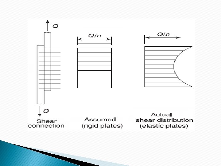
ASSUMPTIONS IN DESIGN OF BEARING BOLTS I. The friction between the plates is negligible. II. Shear is uniform over the cross section of the bolt III. The distribution of stress on the plates between the bolts is uniform. IV. Bolts in a group subjected to direct load share the load equally. V. Bending stress developed in the bolts is neglected.
 =")
BEARING TYPE CONNECTION Stress f = load/area Strength of a bolt ( Load) = ultimate Stress X Area tensile strength, or ultimate tensile strength of bolt can be read from property class 2. No of bolts required= Load/ strength of bolt

Possible Failure Modes 5

DESIGN STRENGTHN CALCULATION STEPS OF BERAING BOLTS cl 10. 3 1. The design strength of bearing bolt is least of the following: (a) Shear Capacity (strength) (b)Bearing Capacity (strength) (c) Tension Capacity (if present) 2. No of bolts required= Load/ strength of bolt 3. Strength of joint will be minimum of the strength of joint on the basis of strength of bolts in the joint and net tensile strength of plate. where Strength of joint on the basis of bolt= strength of bolt× No of bolts 4. Failure of joint can be in plate or bolt

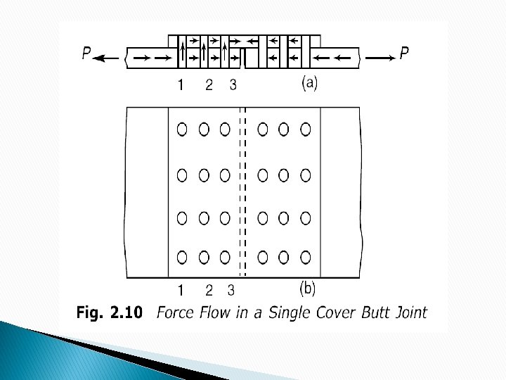
Actions on Bolt Shear, bearing, bending P P P Lap Joint P Bearing and single plane Shear P P Bending Butt Joint P/2 P Bearing and double plane Shear P/2 P P/2

Shear Failure
 The nominal shear capacity of a bolt")
SHEAR STRENGTH OF BOLT (10. 3. 3) The nominal shear capacity of a bolt is given by Vnsb where fub= Ultimate tensile strength of a bolt. nn = number of shear planes with threads intercepting the shear plane, ns = number of shear planes without threads intercepting the shear plane Asb = Nominal Shank area of the Bolt or Area of X section of shank of bolt = π/4*d 2 (EFFECTIVE AREA OF BOLT Cl 10. 3. 1 , P-74) d is nominal diameter of bolt (shank diameter)

Effective area or net area of bolt ie AREA OF BOLT AT ROOT (A nb) Anb= Net area of the bolt at threads, may be taken as the area corresponding to root diameter of the thread Area of Bolt at root of thread is less than shank area of the Bolt. It is taken app = 0. 78 times shank area ie Anb= 0. 78 Asb

Shear Planes With and Without Threads included in the Shear Plane Threads Excluded from the Shear Plane For bolts in single shear, either nn or ns is one and the other is zero. For bolts in double shear the sum of nn and ns is two. 11

The shearing of bolts can take place in the threaded portion of the bolt and so the area at the root of the threads, also called the tensile stress area At, is taken as the shear area Asb. Since threads can occur in the shear plane, the area Ae for resisting shear should normally be taken as the net tensile stress area, An, of the bolts. The shear area is specified in the code and is usually about 0. 78 times the shank area. However, if it is ensured that the threads will not lie in the shear plane then the full area can be taken as the shear area. For bolts in single shear, either nn or ns is one and the other is zero. For bolts in double shear the sum of nn and ns is two.

SHEAR STRENGTH OF BOLT The factored shear force Vnsb should satisfy Vdsb ≤ Vnsb / γmb Where γmb = partial safety factor for the material of the bolt =1. 25 Vdsb = design strength of bolt REDUCTION FACTOR FOR SHEAR CAPACITY OF BOLTS There are three situations suggested by the code for the use of reduction factors for design shear capacity of the Bolts i) Long joint ( distance between first and the last bolt in the direction of load is greater than 15 d. ) ii) Large Grip length ( total thickness of the connected plates exceeds 5 times the dia of bolts (5 d)**. iii) Packing plates are used ( If packing plates of thickness more than 6 mm are used in joints)
 ���� Reduction Factor for Large Grip Lengths")
Reduction factor for long Joints( �� ) ���� Reduction Factor for Large Grip Lengths (������ ) βpk= (1 - 0. 0125 tpk) lj= length of joint and is taken as the distance between the first and last row of bolts in a joint measured in the direction of load transfer. Lg= grip lenth tpk is the thickness of the thicker packing plate in mm d= nominal dia of bolts

REDUCTION FACTOR FOR SHEAR CAPACITY OF BOLTS The nominal capacity, Vnsb, of a bolt in shear is given in the code as βlj = reduction factor which allows for the overloading of end bolts that occur in long connections βlg = reduction factor that allows for the effect of large grip length, βpk = reduction factor to account for packing plates in excess of 6 mm. The factored shear force Vnsb should satisfy Vdsb ≤ Vnsb / γmb ; (γmb = 1. 25) 15

BEARING CAPACITY OF BOLTS If the connected plates are made of high strength steel then failure of bolt can take place by bearing of the plates on the bolts. If the plate material is weaker than the bolt material, then failure will occur by bearing of the bolt on the plate and the hole will elongate.

BEARING CAPACITY OF BOLTS As per IS 800 -2007 , the nominal bearing strength of the bolt is : Vnpb = 2. 5 kb fu d t where kb is smaller of e/(3 do), p/(3 do)-0. 25, fub/ fu and 1. 0, fub = the ultimate tensile stress of the bolt, e is the edge distance, p is the pitch of the fastener along bearing direction, do is the diameter of the bolt hole. fu = Ultimate tensile stress of the plate in MPa d = nominal diameter of the bolt in mm 17

BEARING CAPACITY OF BOLTS t = minimum thicknesses of the connected plates experiencing bearing stress in the same direction ( thickness of thinner plate in lap joint or minimum of sum of cover plates and main plate in butt) The factor kb takes into account inadequate edge distance or pitch and also prevents bearing failure of bolts. If we adopt a minimum edge distance of 1. 5 x bolt hole diameter and a minimum pitch of 2. 5 x diameter of bolt, kb may be approximately taken as 0. 50. Vnpb should be multiplied by a factor 0. 7 for over size or short slotted holes and by 0. 5 for long slotted holes. 18
 For the safety of the joint in bearing, the")
BOLTS IN BEARING (cont. ) For the safety of the joint in bearing, the bearing strength of the bolt called the design bearing strength is Vdpb ≤ Vnpb / γmb ; where γmb = 1. 25 19

TENSILE STRENGTH OF BOLT Tb = factored tensile force <= Tdb The nominal tensile capacity of bolt in tension is given by Tnb = 0. 9 fub Anb < fyb Asb γmb / γm 0 where fub = ultimate tensile stress of bolt fyb = yield stress of bolt Anb = net tensile stress area of bolt (Table 2) Asb = shank area of bolt Γm 0 = the partial safety factor for material resistance governed by yielding- 1. 10 The bolt is safe in tension if the factored tension force, The factored tension force Tb shall satisfy Tb ≤ Tnb / γmb ; γmb = 1. 25 Tdb= 0. 9 fub Anb / γmb If any of the connecting plates is flexible, then additional prying forces must be considered.
 Based on Net Tensile Area 21")
Capacity Of Ordinary Bolts (Grade 4. 6) Based on Net Tensile Area 21

BOLTS SUBJECTED TO COMBINED SHEAR AND TENSION A Bolt required to resist both design shear force Vsb and design tensile force at the same time shall satisfy: - + (�� (�� /Vdsb)�� /�� )�� ≤��. �� ���� �� ���� Where Vsb = factored shear force on bolt Vdsb = design shear capacity of bolt Tb = factored tensile force on bolt Tdb= design tension capacity of bolt

Connection subjected to shear and tension

DESIGN STRENGTH OF PLATES IN A JOINT Plates in a joint made with bearing bolts may fail due to any one of the following: Shearing or bursting of the edge. Crushing of plates. Tensile failure (Rupture) of plates. Block shear failure of plates in tension. The bursting or shearing and crushing failures are avoided if the minimum edge/end distance as per IS 800 -2007 recommendations are provided.

TENSILE STRENGTH OF PLATE If the maximum distances are ensured in a joint, the design tensile strength of plate in the joint is the strength of the thinnest member against rupture. This strength at a critical section is given by Tdn = 0. 9 An fu / γm 1 Where fu= Ultimate stress of material γm 1 = partial safety factor at ultimate stress = 1. 25 An= Net effective area at the critical section

PATTERN OF BOLTS

Critical sections 1. The tensile strength of the main plate will be critical at 1 -1 2. Tensile strength of cover plate will be critical at 3 -3.
;")
Tension Capacity of Plate The pattern of bolts may be chain or staggered (zigzag); staggered pattern being most suitable as it results in more net area. dh= diameter of the bolt hole (2 mm in addition to the diameter of the hole, in case of directly punched holes t = thickness of thinner plate in joint B= width of plate g= gauge length between the bolt holes Ps= staggered pitch length between the lines of bolt holes n= no of bolt holes in the critical section CHAIN BOLTING 29

Tension Capacity of Plate-Staggered Holes 30

STRENGTH OF JOINTS 1. Strength of the joint on the basis of bolts = strength of one bolt X number of bolts 2. Strength of the joint on the basis of plate = tensile strength of the plate Strength of joint = minimum of 1 and 2.

EFFICIENCY OF JOINTS Efficiency of a bolted joint also called the percentage strength of the joint is ratio of the strength of the joint to the strength of the main member expressed as a percentage. The effectiveness of a particular bolted joint is measured by its efficiency.

EFFICIENCY OF JOINTS Strength of the joint can also be found based on per pitch length. For example

ECENTRIC CONNECTION WITH BEARING BOLTS Case-I Load is in the plane of group of bolts P P Pe Eccentricity in the plane of the faying surface Direct Shear + Additional Shear due to moment Pe e

Forces on Eccentrically-Loaded Bolts with Eccentricity on the Faying Surface Elastic Method e P P Pe r 3 d 1 d 3 CG P/3 r 1 d 2 r 2 P/3 Assume plates are perfectly rigid and bolts perfectly elastic rotational displacement at each bolt is proportional to its distance from the CG stress is greatest at bolt farthest from CG

Consider the eccentric connection which is subjected to design load P at an eccentricity e. The load is equivalent to (i) An axial load P (ii) Moment ‘Pe’ acting at the CG of the bolt group Total Force in each bolt is resultant of Force due to direct shear (P) and shear force due to Moment (Pe). This resultant force in each bolt should be less than the strength of the bolt.

Let n be the number of bolts in the bracket connection Let F 1 = Force due to Direct Shear due to axial load = P/n and acts in vertical direction. Let F 2= Force in any bolt due to torque= Pe r/ Σ r 2

Force in any bolt due to torque is proportional to its radial distance from the center of rotation of the connection F 2 α r or F 2= k r (1) So torque about center of rotation of the bolt group ie Total resisting torque = Σ F 2 r This force balances moment = Pe Thus Σ F 2 r = Pe Put value of F 2 Σ k r 2 = Pe or k = Pe/ Σ r 2 (2) Again from Eq 1 F 2= k r ; put k from eq 2 Or F 2 = Pe r/ Σ r 2

Force F 2 is maximum when r is maximum If θ is the angle between F 1 and F 2, then the Resultant force in Bolt is given by F= √ ( F 1 2 + F 2 2 + 2 F 1 F 2 Cos θ ) This should be less than strength of bolt
- Slides: 39