
CDSLTS 2 thermomechanical analysis results Janusz Skrzypacz Jarosaw
- Slides: 25
CDS-LTS 2 thermo-mechanical analysis results Janusz Skrzypacz Jarosław Poliński Przemyslaw Jaszak Maciej Chorowski Critical Design Review Meeting, 11 -12 January 2017, Wroclaw, Poland
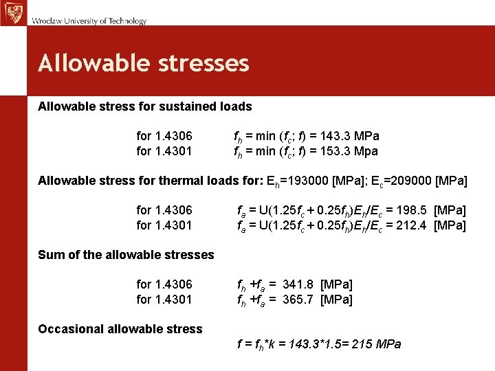
Allowable stresses Allowable stress for sustained loads for 1. 4306 fh = min (fc; f) = 143. 3 MPa for 1. 4301 fh = min (fc; f) = 153. 3 Mpa Allowable stress for thermal loads for: Eh=193000 [MPa]; Ec=209000 [MPa] for 1. 4306 fa = U(1. 25 fc + 0. 25 fh)Eh/Ec = 198. 5 [MPa] for 1. 4301 fa = U(1. 25 fc + 0. 25 fh)Eh/Ec = 212. 4 [MPa] Sum of the allowable stresses for 1. 4306 fh +fa = 341. 8 [MPa] for 1. 4301 fh +fa = 365. 7 [MPa] Occasional allowable stress f = fh*k = 143. 3*1. 5= 215 MPa
Process pipes flexibility analysis
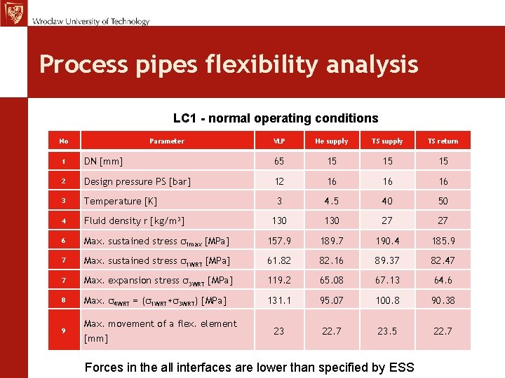
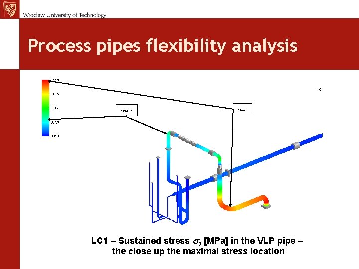
Process pipes flexibility analysis LC 1 - normal operating conditions No Parameter VLP He supply TS return 1 DN [mm] 65 15 15 15 2 Design pressure PS [bar] 12 16 16 16 3 Temperature [K] 3 4. 5 40 50 4 Fluid density r [kg/m 3] 130 27 27 6 Max. sustained stress s 1 max [MPa] 157. 9 189. 7 190. 4 185. 9 7 Max. sustained stress s 1 WRT [MPa] 61. 82 82. 16 89. 37 82. 47 7 Max. expansion stress s 3 WRT [MPa] 119. 2 65. 08 67. 13 64. 6 8 Max. s 4 WRT = (s 1 WRT+s 3 WRT) [MPa] 131. 1 95. 07 100. 8 90. 38 23 22. 7 23. 5 22. 7 9 Max. movement of a flex. element [mm] Forces in the all interfaces are lower than specified by ESS
Process pipes flexibility analysis s 1 WUT s 1 max LC 1 – Sustained stress s 1 [MPa] in the VLP pipe – the close up the maximal stress location
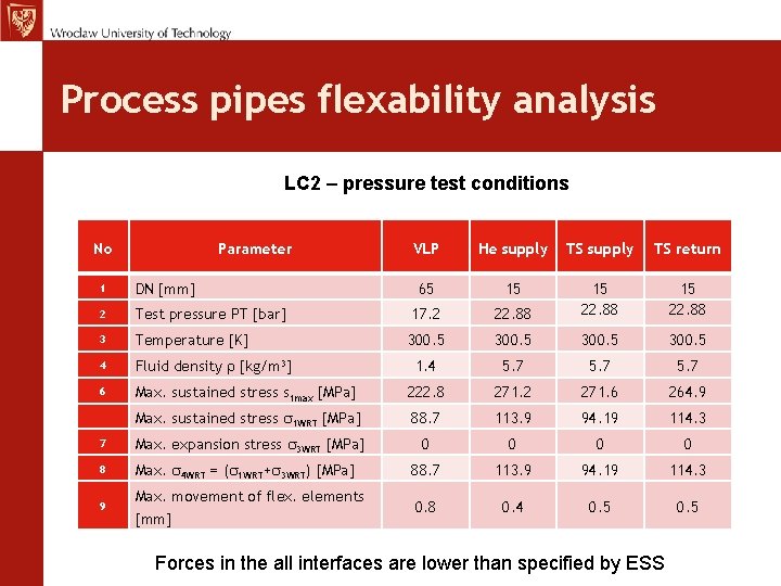
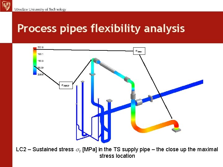
Process pipes flexability analysis LC 2 – pressure test conditions No Parameter VLP He supply TS return 65 15 15 22. 88 1 DN [mm] 2 Test pressure PT [bar] 17. 2 22. 88 15 22. 88 3 Temperature [K] 300. 5 4 Fluid density r [kg/m 3] 1. 4 5. 7 6 Max. sustained stress s 1 max [MPa] 222. 8 271. 2 271. 6 264. 9 Max. sustained stress s 1 WRT [MPa] 88. 7 113. 9 94. 19 114. 3 7 Max. expansion stress s 3 WRT [MPa] 0 0 8 Max. s 4 WRT = (s 1 WRT+s 3 WRT) [MPa] 88. 7 113. 9 94. 19 114. 3 9 Max. movement of flex. elements [mm] 0. 8 0. 4 0. 5 Forces in the all interfaces are lower than specified by ESS
Process pipes flexibility analysis s 1 max s 1 WUT LC 2 – Sustained stress s 1 [MPa] in the TS supply pipe – the close up the maximal stress location
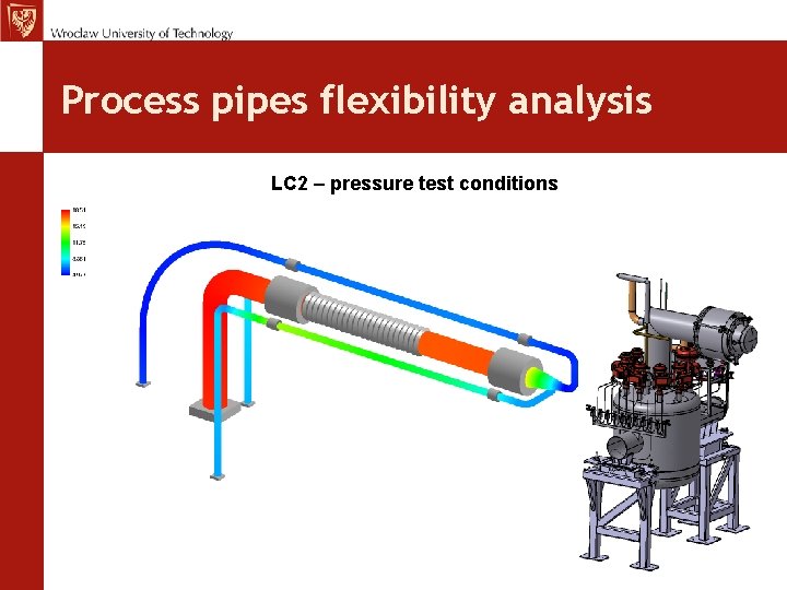
Process pipes flexibility analysis LC 2 – pressure test conditions
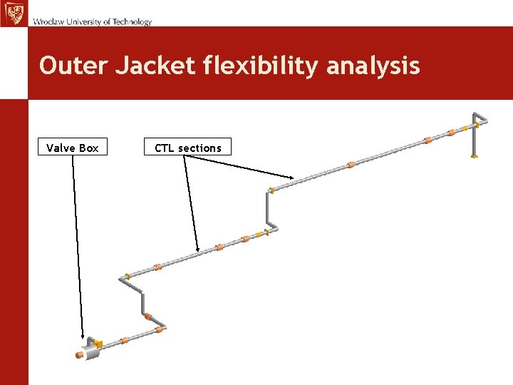
Outer Jacket flexibility analysis Valve Box CTL sections
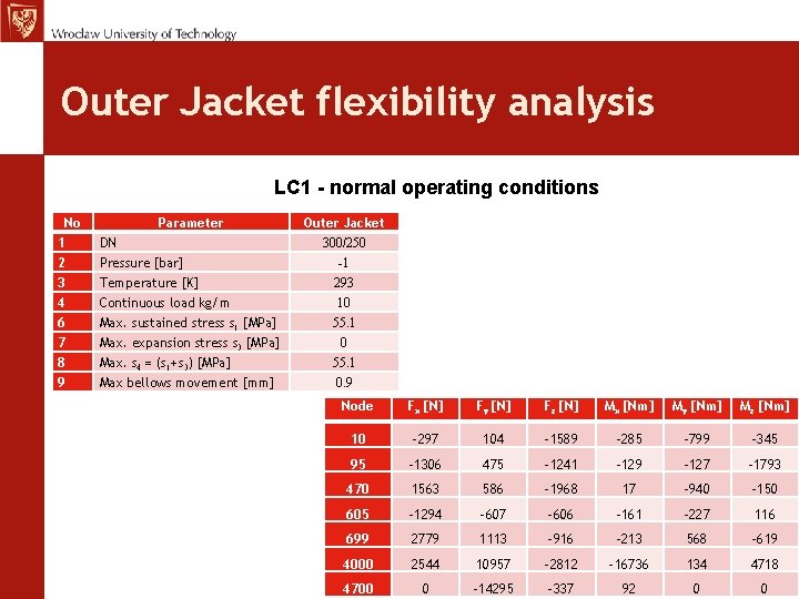
Outer Jacket flexibility analysis LC 1 - normal operating conditions No 1 2 3 4 6 7 8 9 Parameter DN Pressure [bar] Temperature [K] Continuous load kg/m Max. sustained stress s 1 [MPa] Max. expansion stress s 3 [MPa] Max. s 4 = (s 1+s 3) [MPa] Max bellows movement [mm] Outer Jacket 300/250 -1 293 10 55. 1 0. 9 Node Fx [N] Fy [N] Fz [N] Mx [Nm] My [Nm] Mz [Nm] 10 -297 104 -1589 -285 -799 -345 95 -1306 475 -1241 -129 -127 -1793 470 1563 586 -1968 17 -940 -150 605 -1294 -607 -606 -161 -227 116 699 2779 1113 -916 -213 568 -619 4000 2544 10957 -2812 -16736 134 4718 4700 0 -14295 -337 92 0 0
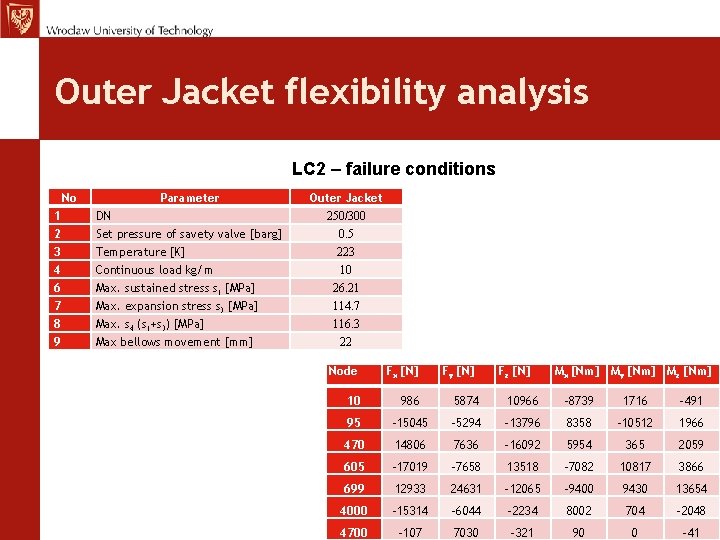
Outer Jacket flexibility analysis LC 2 – failure conditions No 1 2 3 4 6 7 8 9 Parameter DN Set pressure of savety valve [barg] Temperature [K] Continuous load kg/m Max. sustained stress s 1 [MPa] Max. expansion stress s 3 [MPa] Max. s 4 (s 1+s 3) [MPa] Max bellows movement [mm] Outer Jacket 250/300 0. 5 223 10 26. 21 114. 7 116. 3 22 Node Fx [N] Fy [N] Fz [N] Mx [Nm] My [Nm] Mz [Nm] 10 986 5874 10966 -8739 1716 -491 95 -15045 -5294 -13796 8358 -10512 1966 470 14806 7636 -16092 5954 365 2059 605 -17019 -7658 13518 -7082 10817 3866 699 12933 24631 -12065 -9400 9430 13654 4000 -15314 -6044 -2234 8002 704 -2048 4700 -107 7030 -321 90 0 -41
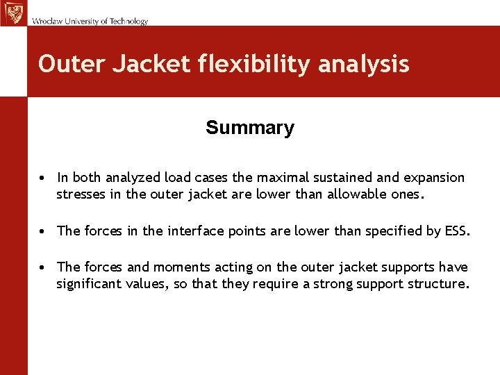
Outer Jacket flexibility analysis Summary • In both analyzed load cases the maximal sustained and expansion stresses in the outer jacket are lower than allowable ones. • The forces in the interface points are lower than specified by ESS. • The forces and moments acting on the outer jacket supports have significant values, so that they require a strong support structure.
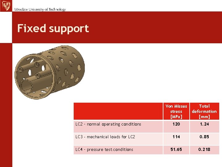
Fixed support Von Misses stress [MPa] Total deformation [mm] LC 2 – normal operating conditions 120 1. 24 LC 3 - mechanical loads for LC 2 114 0. 85 LC 4 – pressure test conditions 51. 65 0. 218
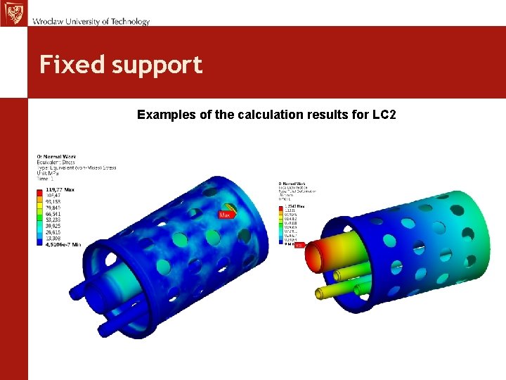
Fixed support Examples of the calculation results for LC 2
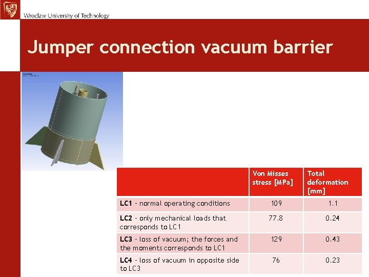
Jumper connection vacuum barrier Von Misses stress [MPa] Total deformation [mm] LC 1 – normal operating conditions 109 1. 1 LC 2 – only mechanical loads that corresponds to LC 1 77. 8 0. 24 LC 3 – loss of vacuum; the forces and the moments corresponds to LC 1 129 0. 43 LC 4 – loss of vacuum in opposite side to LC 3 76 0. 23
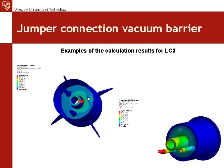
Jumper connection vacuum barrier Examples of the calculation results for LC 3
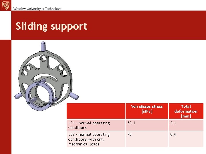
Sliding support Von Misses stress [MPa] Total deformation [mm] LC 1 – normal operating conditions 50. 1 3. 1 LC 2 – normal operating conditions with only mechanical loads 78 0. 4
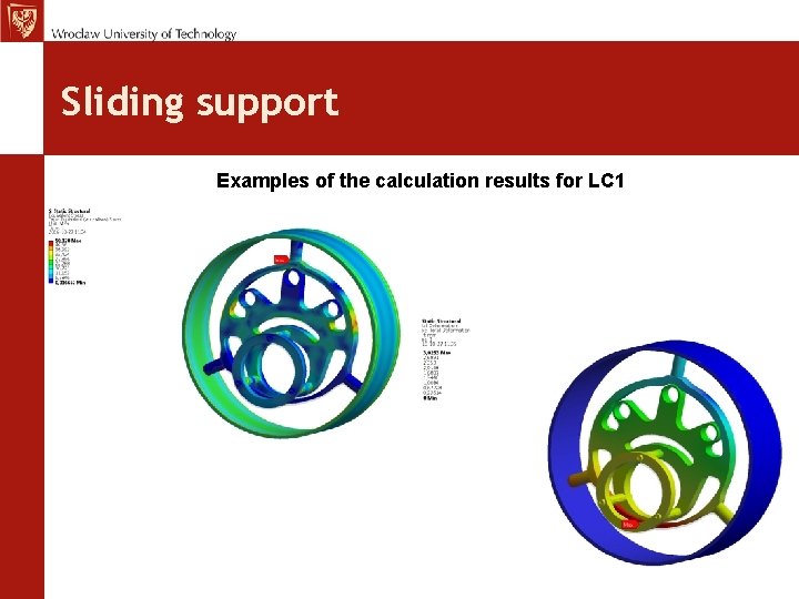
Sliding support Examples of the calculation results for LC 1
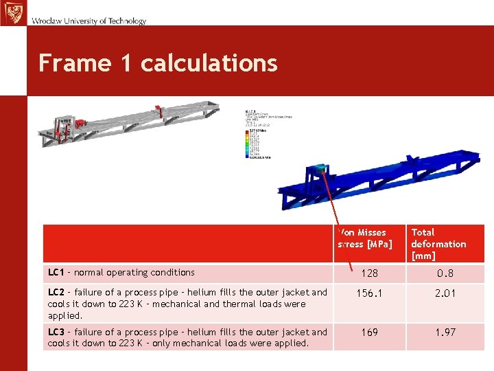
Frame 1 calculations Von Misses stress [MPa] LC 1 – normal operating conditions Total deformation [mm] 128 0. 8 LC 2 – failure of a process pipe – helium fills the outer jacket and cools it down to 223 K – mechanical and thermal loads were applied. 156. 1 2. 01 LC 3 – failure of a process pipe – helium fills the outer jacket and cools it down to 223 K – only mechanical loads were applied. 169 1. 97
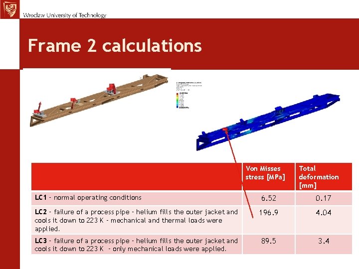
Frame 2 calculations Von Misses stress [MPa] Total deformation [mm] LC 1 – normal operating conditions 6. 52 0. 17 LC 2 – failure of a process pipe – helium fills the outer jacket and cools it down to 223 K – mechanical and thermal loads were applied. 196. 9 4. 04 LC 3 – failure of a process pipe – helium fills the outer jacket and cools it down to 223 K – only mechanical loads were applied. 89. 5 3. 4
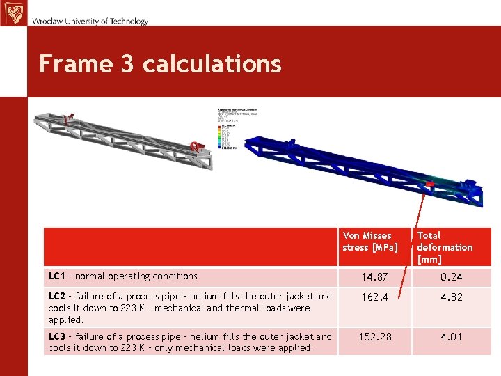
Frame 3 calculations Von Misses stress [MPa] Total deformation [mm] LC 1 – normal operating conditions 14. 87 0. 24 LC 2 – failure of a process pipe – helium fills the outer jacket and cools it down to 223 K – mechanical and thermal loads were applied. 162. 4 4. 82 LC 3 – failure of a process pipe – helium fills the outer jacket and cools it down to 223 K – only mechanical loads were applied. 152. 28 4. 01
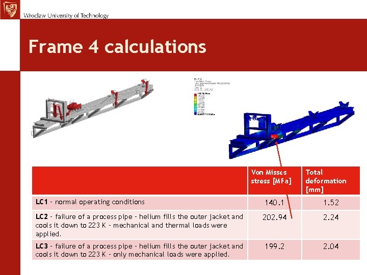
Frame 4 calculations Von Misses stress [MPa] Total deformation [mm] LC 1 – normal operating conditions 140. 1 1. 52 LC 2 – failure of a process pipe – helium fills the outer jacket and cools it down to 223 K – mechanical and thermal loads were applied. 202. 94 2. 24 LC 3 – failure of a process pipe – helium fills the outer jacket and cools it down to 223 K – only mechanical loads were applied. 199. 2 2. 04
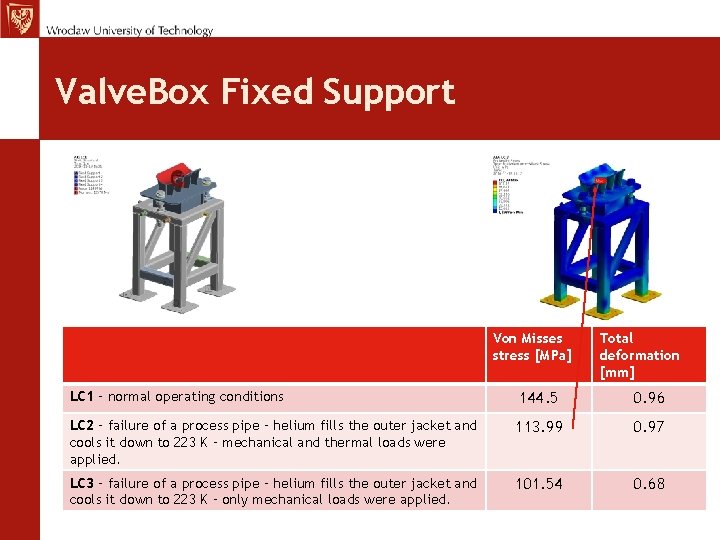
Valve. Box Fixed Support Von Misses stress [MPa] Total deformation [mm] LC 1 – normal operating conditions 144. 5 0. 96 LC 2 – failure of a process pipe – helium fills the outer jacket and cools it down to 223 K – mechanical and thermal loads were applied. 113. 99 0. 97 LC 3 – failure of a process pipe – helium fills the outer jacket and cools it down to 223 K – only mechanical loads were applied. 101. 54 0. 68
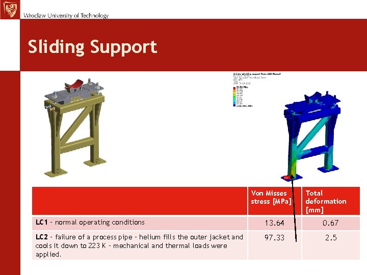
Sliding Support Von Misses stress [MPa] Total deformation [mm] LC 1 – normal operating conditions 13. 64 0. 67 LC 2 – failure of a process pipe – helium fills the outer jacket and cools it down to 223 K – mechanical and thermal loads were applied. 97. 33 2. 5
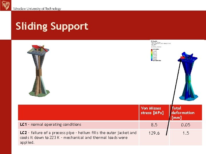
Sliding Support Von Misses stress [MPa] LC 1 – normal operating conditions LC 2 – failure of a process pipe – helium fills the outer jacket and cools it down to 223 K – mechanical and thermal loads were applied. Total deformation [mm] 8. 5 0. 05 129. 6 1. 5