CCNA 1 Chapter 4 Physical Layer Protocols Types


 connect a device to the network.")


 provides better noise protection than UTP cabling.")


")
. • It uses")
 is used with wireless")


- Slides: 57
CCNA - 1 Chapter 4
Physical Layer Protocols
Types of Connections • Before any network communications can occur, a physical connection to a local network must be established. A physical connection can be a wired connection using a cable or a wireless connection using radio waves.
Network Interface Cards • Network Interface Cards (NICs) connect a device to the network. • Ethernet NICs are used for a wired connection, whereas WLAN NICs are used for wireless. • An end-user device may include one or both types of NICs. • Not all physical connections are equal, in terms of the performance level, when connecting to a network. • For example: • a wireless device will experience degradation in performance based on its distance from a wireless access point. • All wireless devices must share access to the airwaves connecting to the wireless access point. This means slower network performance may occur as more wireless devices access the network simultaneously.
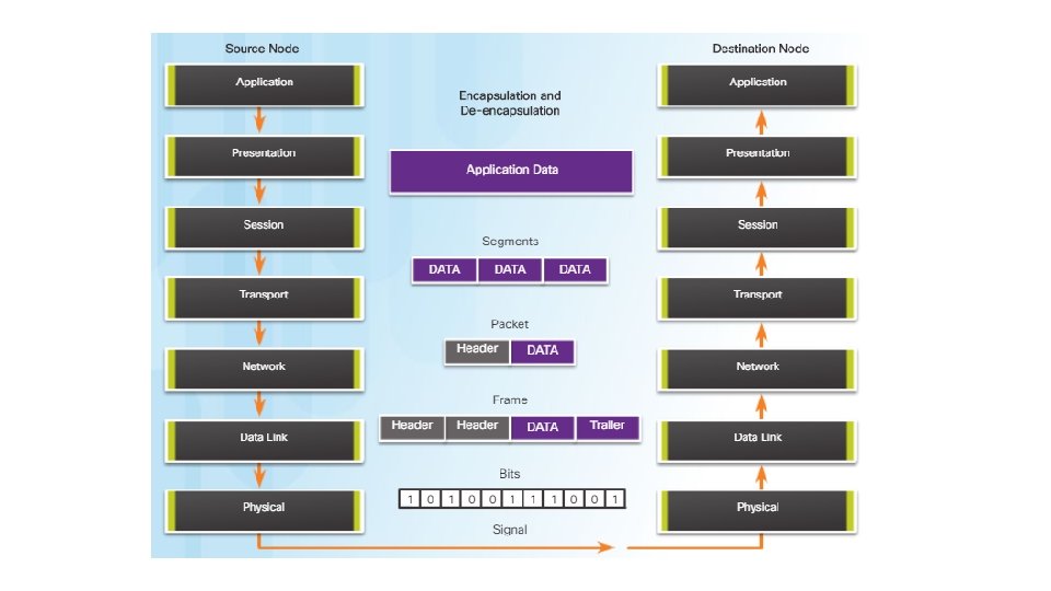
The Physical Layer • The process that data undergoes from a source node to a destination node is: • The user data is segmented by the transport layer, placed into packets by the network layer, and further encapsulated into frames by the data link layer. • The physical layer encodes the frames and creates the electrical, optical, or radio wave signals that represent the bits in each frame. • These signals are then sent on the media, one at a time. • The destination node physical layer retrieves these individual signals from the media, restores them to their bit representations, and passes the bits up to the data link layer as a complete frame.
Physical Layer Media • There are three basic forms of network media. The physical layer produces the representation and groupings of bits for each type of media as: • Copper cable: The signals are patterns of electrical pulses. • Fiber-optic cable: The signals are patterns of light. • Wireless: The signals are patterns of microwave transmissions.
Functions • The physical layer standards address three functional areas: • Physical Components: • The physical components are the electronic hardware devices, media, and other connectors that transmit and carry the signals to represent the bits. Hardware components such as NICs, interfaces and connectors, cable materials, and cable designs are all specified in standards associated with the physical layer. • Encoding or line encoding is a method of converting a stream of data bits into a predefined "code”. In other words, encoding is the method or pattern used to represent digital information. For example, Manchester encoding. • Signaling • The physical layer must generate the electrical, optical, or wireless signals that represent the "1" and "0" on the media. The method of representing the bits is called the signaling method. The physical layer standards must define what type of signal represents a "1" and what type of signal represents a "0".
Physical Layer Characteristics • Different physical media support the transfer of bits at different rates. Data transfer is usually discussed in terms of bandwidth and throughput.
Bandwidth • it is the capacity of a medium to carry data. Digital bandwidth measures the amount of data that can flow from one place to another in a given amount of time. • Bandwidth is typically measured in kilobits per second (kb/s), megabits per second (Mb/s), or gigabits per second (Gb/s). • A combination of factors determines the practical bandwidth of a network: • The properties of the physical media • The technologies chosen for signaling and detecting network signals
Throughput • It is the measure of the transfer of bits across the media over a given period of time. • Due to a number of factors, throughput usually does not match the specified bandwidth in physical layer implementations. • Many factors influence throughput, including: • The amount of traffic • The type of traffic • The latency created by the number of network devices encountered between source and destination
Goodput • There is a third measurement to assess the transfer of usable data that is known as goodput. • Goodput is the measure of usable data transferred over a given period of time. • Goodput is throughput minus traffic overhead for establishing sessions, acknowledgments, and encapsulation.
Network Media
Wired Media
Copper Media • There are three main types of copper media used in networking: • Unshielded Twisted-Pair (UTP) • Shielded Twisted-Pair (STP) • Coaxial • These cables are used to interconnect nodes on a LAN and infrastructure devices such as switches, routers, and wireless access points.
Unshielded Twisted-Pair Cable • UTP cable consists of four pairs of color-coded wires that have been twisted together and then encased in a flexible plastic sheath that protects from minor physical damage. • The twisting of wires helps protect against signal interference from other wires. • Where two wires are located adjacent to one another so each magnetic field cancels out the adjacent magnetic field. This property called Cancellation is a of UTP cabling.
Types of UTP Cable • Ethernet Straight-through: The most common type of networking cable. It is commonly used to interconnect a host to a switch and a switch to a router. • Ethernet Crossover: A cable used to interconnect similar devices. For example to connect a switch to a switch, a host to a host, or a router to a router. • Rollover: A Cisco proprietary cable used to connect a workstation to a router or switch console port.
Shielded Twisted-Pair Cable • Shielded twisted-pair (STP) provides better noise protection than UTP cabling. However, compared to UTP cable, STP cable is significantly more expensive and difficult to install. • STP cables combine the techniques of shielding to counter EMI and RFI, and wire twisting to counter crosstalk. • The STP cable shown uses four pairs of wires, each wrapped in a foil shield, which are then wrapped in an overall metallic braid or foil.
Coaxial Cable • Coaxial cable, or coax for short, gets its name from the fact that there are two conductors that share the same axis. • Coaxial cable consists of: • A copper conductor used to transmit the electronic signals. • A layer of flexible plastic insulation surrounding a copper conductor. • The insulating material is surrounded in a woven copper braid, or metallic foil, that acts as the second wire in the circuit and as a shield for the inner conductor. This second layer, or shield, also reduces the amount of outside electromagnetic interference. • The entire cable is covered with a cable jacket to prevent minor physical damage. • UTP cable has essentially replaced coaxial cable in modern Ethernet installations
Fiber-Optic Cabling • Optical fiber cable transmits data over longer distances and at higher bandwidths than any other networking media. • Unlike copper wires, fiber-optic cable can transmit signals with less attenuation and is completely immune to EMI and RFI. • Optical fiber is a flexible, but extremely thin. • Bits are encoded on the fiber as light impulses. • The fiber-optic cable acts as a waveguide to transmit light between the two ends with minimal loss of signal. • Optical fiber is composed of two kinds of glass (core and cladding) and a protective outer shield (jacket). • Although the optical fiber is very thin and susceptible to sharp bends, the properties of the core and cladding make it very strong. Optical fiber is durable and is deployed in harsh environmental conditions in networks all around the world.
Fiber versus Copper
Wireless Media
Types of Wireless Media • Wireless media carry electromagnetic signals that represent the binary digits of data communications using radio or microwave frequencies. • The IEEE and telecommunications industry standards for wireless data communications cover both the data link and physical layers. (Wi Fi , Bluetooth , Wi max) • Other wireless technologies such as cellular and satellite communications can also provide data network connectivity.
Data Link Layer
Functions • Allowing the upper layers to access the media • Accepting Layer 3 packets and packaging them into frames • Preparing network data for the physical network • Controlling how data is placed and received on the media • Exchanging frames between nodes over a physical network media, such as UTP or fiber-optic • Receiving and directing packets to an upper layer protocol • Performing error detection
Data Link Sublayers • The data link layer is divided into two sublayers: • Logical Link Control (LLC) - This upper sublayer communicates with the network layer. It places information in the frame that identifies which network layer protocol is being used for the frame. This information allows multiple Layer 3 protocols, such as IPv 4 and IPv 6, to utilize the same network interface and media. • Media Access Control (MAC) - This lower sublayer defines the media access processes performed by the hardware. It provides data link layer addressing and access to various network technologies.
WAN Topologies
Common Physical WAN Topologies • Point-to-Point - This is the simplest topology that consists of a permanent link between two endpoints. For this reason, this is a very popular WAN topology. • Hub and Spoke - A WAN version of the star topology in which a central site interconnects branch sites using point-to-point links. • Mesh - This topology provides high availability, but requires that every end system be interconnected to every other system. Therefore, the administrative and physical costs can be significant. Each link is essentially a point-to-point link to the other node. • A hybrid is a variation or combination of any of the above topologies. For example, a partial mesh is a hybrid topology in which some, but not all, end devices are interconnected.
LAN Topologies
Common Physical LAN Topologies • Star - End devices are connected to a central intermediate device. The star topology is easy to install, very scalable (easy to add and remove end devices), and easy to troubleshoot. • Extended Star - In an extended star topology, additional central intermediate device interconnect other star topologies. An extended star is an example of a hybrid topology. • Bus - All end systems are chained to each other and terminated in some form on each end. Infrastructure devices such as switches are not required to interconnect the end devices. • Ring - End systems are connected to their respective neighbor forming a ring. Unlike the bus topology, the ring does not need to be terminated.
Common Physical LAN Topologies
Half and Full Duplex • Duplex communications refer to the direction of data transmission between two devices. • Half-duplex communications restrict the exchange of data to one direction at a time while full-duplex allows the sending and receiving of data to happen simultaneously.
Media Access Control Methods • Some multi-access networks require rules to govern how devices share the physical media. There are two basic access control methods for shared media: • Contention-based access - All nodes operating in half-duplex compete for the use of the medium, but only one device can send at a time. Ethernet LANs using hubs and WLANs are examples of this type of access control. • Controlled access - Each node has its own time to use the medium. These deterministic types of networks are inefficient because a device must wait its turn to access the medium. Legacy Token Ring LANs are an example of this type of access control.
Contention-Based Access – CSMA/CD • • • The Carrier Sense Multiple Access/Collision Detection (CSMA/CD) process is used in half-duplex Ethernet LANs The CSMA process is as follows: 1. PC 1 has an Ethernet frame to send to PC 3. 2. PC 1’s NIC needs to determine if anyone is transmitting on the medium. If it does not detect a carrier signal, in other words, it is not receiving transmissions from another device, it will assume the network is available to send. 3. PC 1’s NIC sends the Ethernet Frame. 4. The Ethernet hub receives the frame. An Ethernet hub is also known as a multiport repeater. Any bits received on an incoming port are regenerated and sent out all other ports. 5. If another device, such as PC 2, wants to transmit, but is currently receiving a frame, it must wait until the channel is clear. 6. All devices attached to the hub will receive the frame. Because the frame has a destination data link address for PC 3, only that device will accept and copy in the entire frame. All other devices’ NICs will ignore the frame. The CD process is: If two devices transmit at the same time, a collision will occur. Both devices will detect the collision on the network, this is the collision detection (CD). This is done by the NIC comparing data transmitted with data received. The data sent by both devices will be corrupted and will need to be resent.
Contention-Based Access – CSMA/CA • Carrier Sense Multiple Access/Collision Avoidance (CSMA/CA). • It uses a method similar to CSMA/CD to detect if the media is clear. It uses additional techniques. • CSMA/CA does not detect collisions but attempts to avoid them by waiting before transmitting. • Each device that transmits includes the time duration that it needs for the transmission. All other wireless devices receive this information and know how long the medium will be unavailable • After a wireless device sends a frame, the receiver returns an acknowledgment so that the sender knows the frame arrived.
• Carrier sense multiple access with collision avoidance (CSMA/CA) is used with wireless networking technology to mediate media contention. • Carrier sense multiple access with collision detection (CSMA/CD) is used with wired Ethernet technology to mediate media contention.
CCNA - 1 Chapter 5
Ethernet Protocol
Data encapsulation • The data encapsulation process includes frame assembly before transmission, and frame disassembly upon reception of a frame. • Data encapsulation provides three primary functions: • Frame delimiting - The framing process provides important delimiters that are used to identify a group of bits that make up a frame. These delimiting bits provide synchronization between the transmitting and receiving nodes. • Addressing - The encapsulation process contains the Layer 3 PDU and also provides for data link layer addressing. • Error detection - Each frame contains a trailer used to detect any errors in transmissions.
Ethernet Frame • Ethernet is the most widely used LAN technology today. • Ethernet operates in the data link layer and the physical layer. • It is a family of networking technologies that are defined in the IEEE 802. 2 and 802. 3 standards. • The Ethernet frame includes: the source and destination physical address. The trailer includes a CRC value in the Frame Check Sequence field to allow the receiving device to determine if the frame has been changed (has errors) during the transmission. • Ethernet relies on the two separate sublayers of the data link layer to operate, the Logical Link Control (LLC) and the MAC sublayers. • LLC sublayer - The Ethernet LLC sublayer handles the communication between the network layers and the datalink layers. This is typically between the networking software and the device hardware. The LLC sublayer takes the network protocol data, which is typically an IPv 4 packet, and adds control information to help deliver the packet to the destination node. • MAC sublayer - MAC constitutes the lower sublayer of the data link layer. MAC is implemented by hardware, typically in the computer NIC.
Ethernet Frame size • The minimum Ethernet frame size is 64 bytes and the maximum is 1518 bytes. • Any frame less than 64 bytes in length is considered a “collision fragment” or “runt frame” and is automatically discarded by receiving stations. Frames with more than 1500 bytes of data are considered “jumbo” or “baby giant frames”. • If the size of a transmitted frame is less than the minimum or greater than the maximum, the receiving device drops the frame.
MAC Address • Media access control address is responsible for the placement of frames on the media and the removal of frames from the media. As its name implies, it controls access to the media. • In an Ethernet network, each NIC in the network checks every arriving frame to see if the destination MAC address in the frame matches its own MAC address. If there is no match, the device discards the frame. If there is a match, the NIC passes the frame up to the next OSI layer. • An Ethernet MAC address is a 48 -bit binary value expressed as 12 hexadecimal digits. • MAC addresses must be globally unique by design. • MAC addresses are in flat structure and thus they are not routable on the Internet. • Serial interfaces do not use MAC addresses.
Switch Fundamentals • A Layer 2 Ethernet switch uses MAC addresses to make forwarding decisions. It is completely unaware of the protocol being carried in the data portion of the frame, such as an IPv 4 packet. The switch makes its forwarding decisions based only on the Layer 2 Ethernet MAC addresses. • an Ethernet switch consults a MAC address table to make a forwarding decision for each frame. • The switch dynamically builds the MAC address table by examining the source MAC address of the frames received on a port. The switch forwards frames by searching for a match between the destination MAC address in the frame and an entry in the MAC address table. • The following process is performed on every Ethernet frame that enters a switch. • Learn – Examining the Source MAC Address • Forward – Examining the Destination MAC Address • Note: A switch will flood a frame out of every port, except the one that the frame was received from, under two circumstances. Either the frame has the broadcast address as the destination address, or the destination address is unknown to the switch.
Frame Forwarding Methods on Cisco Switches • Switches use one of the following forwarding methods for switching data between network ports: • Store-and-forward switching • Cut-through switching • Fast-forward switching - Fast-forward switching offers the lowest level of latency. Fast-forward switching immediately forwards a packet after reading the destination address. Because fastforward switching starts forwarding before the entire packet has been received, there may be times when packets are relayed with errors. • Fragment-free switching - In fragment-free switching, the switch stores the first 64 bytes of the frame before forwarding. Fragment-free switching can be viewed as a compromise between store-andforward switching and fast-forward switching. The reason fragment-free switching stores only the first 64 bytes of the frame is that most network errors and collisions occur during the first 64 bytes. Performing a small error check on the first 64 bytes of the frame to ensure that a collision has not occurred before forwarding the frame.
Example: frame from A to B
ARP Functions • When a device sends an Ethernet frame, it contains these two addresses: • Destination MAC address - The MAC address of the Ethernet NIC, which will be either the MAC address of the final destination device or the router. • Source MAC address - The MAC address of the sender’s Ethernet NIC. • ARP, or the Address Resolution Protocol, works by mapping a destination MAC address to a destination IPv 4 address. The host knows the destination IPv 4 address and uses ARP to resolve the corresponding destination MAC address. • ARP provides two basic functions: • Resolving IPv 4 addresses to MAC addresses • Maintaining a table of mappings
CCNA - 1 Chapter 6
Network Layer
The Network Layer • The network layer, or OSI Layer 3, provides services to allow end devices to exchange data across the network. To accomplish this end-to-end transport, the network layer uses four basic processes: • Addressing end devices - End devices must be configured with a unique IP address for identification on the network. • Encapsulation - The network layer encapsulates the protocol data unit (PDU) from the transport layer into a packet. The encapsulation process adds IP header information, such as the IP address of the source (sending) and destination (receiving) hosts. • Routing - The network layer provides services to direct packets to a destination host on another network. To travel to other networks, the packet must be processed by a router. The role of the router is to select the best path and direct packets toward the destination host in a process known as routing. A packet may cross many intermediary devices before reaching the destination host. Each router a packet crosses to reach the destination host is called a hop. • De-encapsulation - When the packet arrives at the network layer of the destination host, the host checks the IP header of the packet. If the destination IP address within the header matches its own IP address, the IP header is removed from the packet. After the packet is de-encapsulated by the network layer, the resulting Layer 4 PDU is passed up to the appropriate service at the transport layer.
IPv 4 Packet Header • Significant fields in the IPv 4 header include: • Version - Contains a 4 -bit binary value set to 0100 that identifies this as an IP version 4 packet. • Differentiated Services or Diff. Serv (DS) - Formerly called the Type of Service (To. S) field, the DS field is an 8 -bit field used to determine the priority of each packet. • Time-to-Live (TTL) - Contains an 8 -bit binary value that is used to limit the lifetime of a packet. The packet sender sets the initial TTL value, and it is decreased by one each time the packet is processed by a router. If the TTL field decrements to zero, the router discards the packet and sends an Internet Control Message Protocol (ICMP) Time Exceeded message to the source IP address. • Protocol - Field is used to identify the next level protocol. This 8 -bit binary value indicates the data payload type that the packet is carrying, which enables the network layer to pass the data to the appropriate upper-layer protocol. Common values include ICMP (1), TCP (6), and UDP (17). • Source IPv 4 Address - Contains a 32 -bit binary value that represents the source IPv 4 address of the packet. The source IPv 4 address is always a unicast address. • Destination IPv 4 Address - Contains a 32 -bit binary value that represents the destination IPv 4 address of the packet. The destination IPv 4 address is a unicast, multicast, or broadcast address.
Host Routing Tables • On a Windows host, the route print or netstat -r command can be used to display the host routing table. Both commands generate the same output.
Router Packet Forwarding Decision • When a host sends a packet to another host, it will use its routing table to determine where to send the packet. If the destination host is on a remote network, the packet is forwarded to the default gateway. • A packet arrives at the default gateway, which is usually a router. The router looks at its routing table to determine where to forward packets. • The routing table of a router can store information about: • Directly-connected routes - These routes come from the active router interfaces. Routers add a directly connected route when an interface is configured with an IP address and is activated. • Remote routes - These routes come from remote networks connected to other routers. Routes to these networks can be manually configured on the local router by the network administrator or dynamically configured using a dynamic routing protocol. • Default route – Like a host, routers also use a default route as a last resort if there is no other route to the desired network in the routing table.
IPv 4 Router Routing Table • On a Cisco IOS router, the show ip route command can be used to display the router’s IPv 4 routing table, as shown in the figure. • C - Identifies a directly-connected network. Directly-connected networks are automatically created when an interface is configured with an IP address and activated. • L - Identifies that this is a local interface. This is the IPv 4 address of the interface on the router.
A Router is a Computer • All router models are essentially computers. Just like computers, tablets, and smart devices, routers also require: • Central processing units (CPU). • Operating systems (OS). • Memory consisting of random-access memory (RAM), read-only memory (ROM), nonvolatile random-access memory (NVRAM), and flash.
Router CPU and OS • Cisco devices require a CPU to execute OS instructions, such as system initialization, routing functions, and switching functions. • The CPU requires an OS to provide routing and switching functions.
Router Memory • RAM - This is volatile memory used in Cisco routers to store applications, processes, and data needed to be executed by the CPU. Cisco routers use a fast type of RAM called synchronous dynamic random access memory (SDRAM). Click RAM in the figure to view more information. • ROM - This non-volatile memory is used to store crucial operational instructions and a limited IOS. Specifically, ROM is firmware embedded on an integrated circuit inside the router which can only be altered by Cisco. Click ROM in the figure to view more information. • NVRAM – This is non-volatile memory is used as the permanent storage for the startup configuration file (startup-config). • Flash - This non-volatile computer memory used as permanent storage for the IOS and other system related files such as log files, voice configuration files, HTML files, backup configurations, and more. When a router is rebooted, the IOS is copied from flash into RAM.
Router Memory