CC 410 System Programming Dr Manal Helal Fall


 – START, END, BYTE, WORD,")
 – A buffer is")


 will be")


 Code W=0 (byte) W=1 (word) W=1 (double word)")
![R/M Field (16 -bit addressing mode) code function 000 [BX+SI] 001 [BX+DI] 010 [BP+SI]](https://slidetodoc.com/presentation_image/231a7a2a5342bdb768385b747468c1cd/image-28.jpg "R/M Field (16 -bit addressing mode) code function 000 [BX+SI] 001 [BX+DI] 010 [BP+SI]")
![R/M Field (32 -bit addressing mode) code function 000 [EAX] 001 [ECX] 010 [EDX]](https://slidetodoc.com/presentation_image/231a7a2a5342bdb768385b747468c1cd/image-29.jpg "R/M Field (32 -bit addressing mode) code function 000 [EAX] 001 [ECX] 010 [EDX]")

![Example MOV DL, [DI] D =1 from memory to register W=0 DATA SIZE IS](https://slidetodoc.com/presentation_image/231a7a2a5342bdb768385b747468c1cd/image-31.jpg "Example MOV DL, [DI] D =1 from memory to register W=0 DATA SIZE IS")

- Slides: 32
CC 410: System Programming Dr. Manal Helal – Fall 2014 – Lecture 4 - Assembler 1
Learning Objectives • Understand Assemblers functions • Differentiate machine dependant vs machine independent features 2
Assembler Definition: An Assembler is a Program that has the following tasks: 1. Transform assembly instructions (source code, such as MOV) into machine code (binary, such as 100010) 2. Assign memory addresses to symbolic labels 3. Create an object code file Source Program Assembler Object Code Linker Executable Code Loader 3
2. 1 Basic Assembler Functions » Figure 2. 1 shows an assembler language program for SIC. – The line numbers are for reference only. – Indexing addressing is indicated by adding the modifier “X” – Lines beginning with “. ” contain comments only. – Reads records from input device (code F 1) – Copies them to output device (code 05) – At the end of the file, writes EOF on the output device, then RSUB to the operating system 4
5
6
7
2. 1 Basic Assembler Functions » Assembler directives (pseudo-instructions) – START, END, BYTE, WORD, RESB, RESW. – These statements are not translated into machine instructions. – Instead, they provide instructions to the assembler itself. 8
2. 1 Basic Assembler Functions » Data transfer (RD, WD) – A buffer is used to store record – Buffering is necessary for different I/O rates – The end of each record is marked with a null character (0016) – Buffer length is 4096 Bytes – The end of the file is indicated by a zerolength record » Subroutines (JSUB, RSUB) 9
2. 1. 1 A simple SIC Assembler » Figure 2. 2 shows the generated object code for each statement. – Loc gives the machine address in Hex. – Assume the program starting at address 1000. » Translation functions – Translate STL to 14. – Translate RETADR to 1033. – Build the machine instructions in the 10 proper format (, X).
11
12
13
2. 1. 1 A simple SIC Assembler » A forward reference – 10 1000 FIRST STL RETADR 141033 – A reference to a label (RETADR) that is defined later in the program – Most assemblers make two passes over the source program » Most assemblers make two passes over source program. – Pass 1 scans the source for label definitions and assigns address (Loc). – Pass 2 performs most of the actual translation. 14
2. 1. 1 A simple SIC Assembler » The object program (OP) will be loaded into memory for execution. » Three types of records – Header: program name, starting address, length. – Text: starting address, length, object code. – End: address of first executable instruction. 15
2. 1. 1 A simple SIC Assembler 16
2. 1. 1 A simple SIC Assembler » The symbol ^ is used to separate fields. – Figure 2. 3 1 E(H)=30(D)=16(D)+14(D) 17
2. 1. 1 A simple SIC Assembler » Assembler’s Functions – Convert mnemonic operation codes to their machine language equivalents • STL to 14 – Convert symbolic operands (referred label) to their equivalent machine addresses • RETADR to 1033 – Build the machine instructions in the proper format – Convert the data constants to internal machine representations – Write the object program and the assembly listing 18
2. 1. 1 A simple SIC Assembler » Example of Instruction Assemble – Forward reference – STCH BUFFER, X 549039 (54)16 1 (001)2 (039)16 19
2. 1. 1 A simple SIC Assembler » Forward reference – Reference to a label that is defined later in the program. Loc Label OP Code Operand 1000 FIRST STL RETADR 1003 … 1012 … 1033 CLOOP … JSUB … J … RESW RDREC … CLOOP … 1 … RETADR 20
2. 1. 1 A simple SIC Assembler » The functions of the two passes assembler. » Pass 1 (define symbol) – Assign addresses to all statements (generate LOC). – Save the values (address) assigned to all labels for Pass 2. – Perform some processing of assembler directives. » Pass 2 – Assemble instructions. – Generate data values defined by BYTE, WORD. – Perform processing of assembler directives not done during Pass 1. – Write the OP (Fig. 2. 3) and the assembly listing (Fig. 2. 2). 21
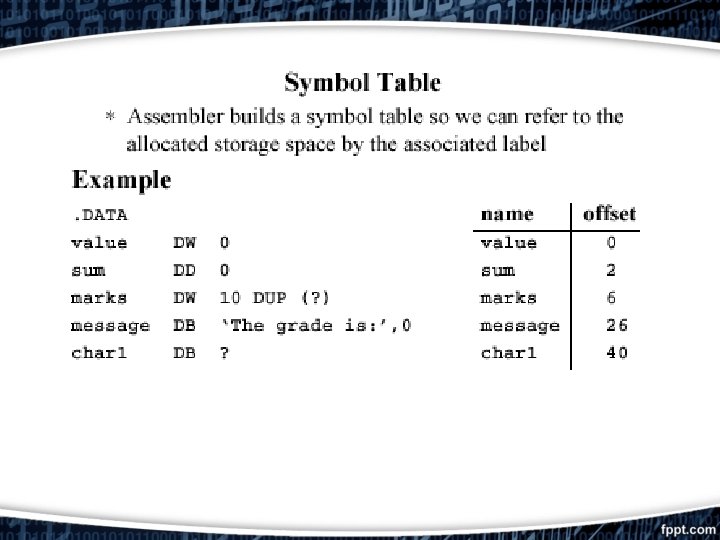
Intel Architecture Assembler Example
1 st Table: Symbol Table Symbol table: List of “items” in this file that may be used by this and other files. What are they? – Labels: function calling – Data: anything in the. data section; variables which may be accessed across files First Pass: record label-address pairs Second Pass: produce machine code – Result: can jump to a label later in code without first declaring it
Generating Machine Code for an Instruction This is complex due to the large variety of addressing modes combined with the large number of instructions. Most often, the machine code for an instruction consists of 1) an 8 -bit opcode (the choice of opcode will depend somewhat on the addressing modes used for the operands) followed by 2) one or more bytes describing the addressing modes for the operands. Instruction format of the pentium 4 microprocessor Op-code 1 -2 bytes Mod-Reg-R/M Displacement 0 -1 bytes 0 -4 bytes immediate 0 -4 bytes
1 - MOD-REG-R/M byte MOD REG R/M -Mod Field: addressing mode = 00 , 01, 10 the R/M (register/Memory) selects one of the data memory addressing modes 00 no displacement, read from first operand from REG and second operand from R/M 01 8 -bit displacement 10 16 -bit displacement = 11 it selects the register addressing mode, Register addressing uses R/M field to specify a register instead of memory location
REG and R/M Field (when MOD=11) Code W=0 (byte) W=1 (word) W=1 (double word) 000 AL AX EAX 001 CL CX ECX 010 DL DX EDX 011 BL BX EBX 100 AH SP ESP 101 CH BP EBP 110 DH SI ESI 111 BH DI EDI
R/M Field (16 -bit addressing mode) code function 000 [BX+SI] 001 [BX+DI] 010 [BP+SI] 011 [BP+DI] 100 [SI] 101 [DI] 110 [BP]/DISP 16 111 [BX]
R/M Field (32 -bit addressing mode) code function 000 [EAX] 001 [ECX] 010 [EDX] 011 [EBX] 100 Displacement 101 [EBP] 110 [ESI] 111 [EDI]
1 - op-code Byte D W -If D=1 then data transferred to the REG field from the R/M field (second operand) -If D=0 then data transferred to the R/M field from the REG field (first operand) - W=1 if data size is a word or double word -W=0 if data size is a byte
Example MOV DL, [DI] D =1 from memory to register W=0 DATA SIZE IS BYTE MODE=No displacement = 00 1 0 0 0 MOD 0 0 0 1 1 0 0 1 REG 100010101 then the hexadecimal code is (machine code) : 8 A 15 D W 1 0 0 1 R/M
Example MOV BP, SP MODE= register addressing mode= 11 D =1 from “memory field” to “register field” W=1 DATA SIZE IS WORD 1 1 0 1 MOD 0 1 0 1 REG 1000101111101100 then the hexadecimal code is (machine code) : 8 BEC D W 1 1 0 0 R/M