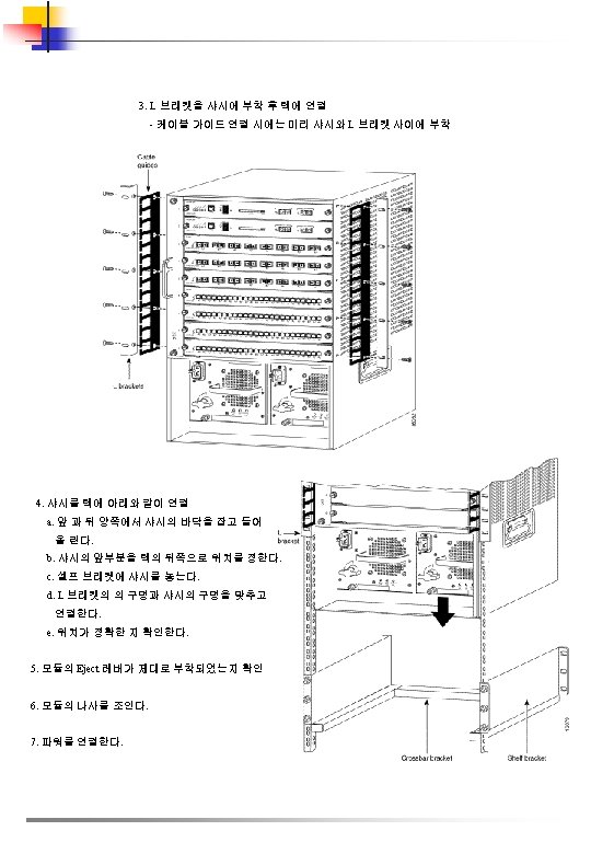
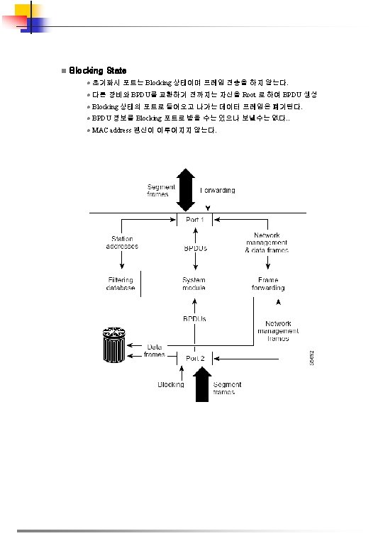
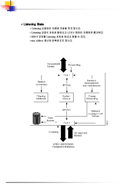
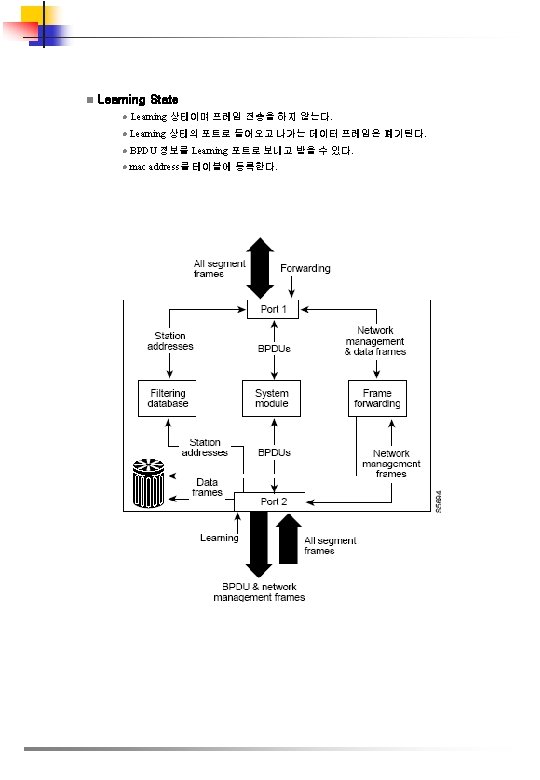
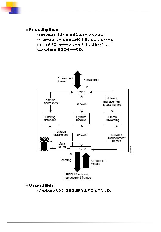
Catalyst 6500 1 Catalys 6500 Hardware Installation 1


 n 개요 l Cisco. Assure end-to-end")
 n 개요 l Catalyst 6500")


 n 특징 l High bandwidth architecture를 지원하는")


 -")


 설정 n l 인터페이스를 트렁트로 고정하여 설정하지 않고, auto 나 desirable")


# interface")


E 이후 버전에서 VTP pruning 설정은 아래와 같다. . Router# configure")
# vtp mode {client")
# vtp mode client")


 VLAN 기본값과 범위 Parameter Default Range VLAN ID 1003 1")


# vlan")


위한 routing 설정과 Layer 3")


# interface")

# no l 2")


# spanning-tree vlan_ID root primary [diameter hops [hello-time")


# spanning-tree vlan 200 priority 33792 Router(config)# end Router# show spanning-tree")


# match {ip address {1 -199 | 1300")
# vlan filter map_name {vlan-list vlan_list |")


# fabric lcd-banner d message d LCD 메시지")
![l 패브릭 상태 보기 Command Purpose Router# show fabric status [slot_number | all] 패브릭](https://slidetodoc.com/presentation_image_h/aed0dcd0e57b16df91610511a9006215/image-113.jpg "l 패브릭 상태 보기 Command Purpose Router# show fabric status [slot_number | all] 패브릭")
![l 패브릭 에러 보기 Command Purpose Router# show fabric errors [slot_number | all] 패브릭](https://slidetodoc.com/presentation_image_h/aed0dcd0e57b16df91610511a9006215/image-114.jpg "l 패브릭 에러 보기 Command Purpose Router# show fabric errors [slot_number | all] 패브릭")


- Slides: 116
Catalyst 6500 매뉴얼
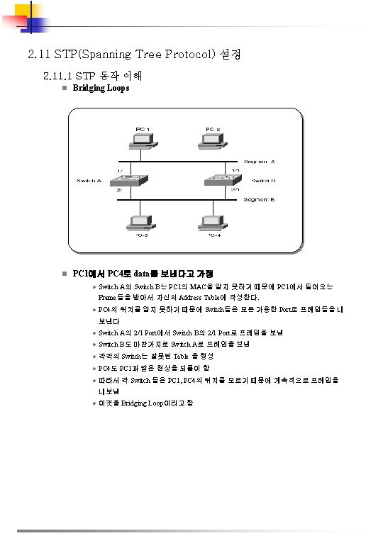
목 차 1. Catalys 6500 Hardware Installation 1. 1 1. 2 1. 3 1. 4 장비 개요 특성 주요 모듈 장비 설치 2. Catalys 6500 Configuration Guide 2. 1 CLI 명령어 2. 2 초기 스위치 설정 2. 3 RPR and RPR+ Supervisor Engine Redundancy 설정 2. 4 인터페이스 설정 2. 5 Layer 2 Switching을 위한 LAN 포트 설정 2. 6 VTP 설정 2. 7 VLANs 2. 8 Layer 3 인터페이스 설정 2. 9 Ether. Channels 설정 2. 10 IEEE 802. 1 Q Trunk 설정 2. 11 STP(Spanning Tree Protocol) 설정 2. 12 IP Unicast Layer 3 Switching 설정 2. 13 Network Security 설정 2. 14 SFM(Switch Fabric Module) 설정 2. 15 파워 및 환경 모니터링 1
n장비 구조 l Standard Network Protocol è IEEE 802. 1 Q, 802. 1 p, 802. 3 x è 이더넷 : IEEE 802. 3, 10 Base. T, and 10 Base. FL è Fast Ethernet : IEEE 802. 3 u, 100 Base. TX, 100 Base. FX è Gigabit Ethernet : IEEE 802. 3 z è 10 Gigabit Ethernet : IEEE 802. 3 ae l Network 관리 è CWSI graphical user interface(GUI) è Cisco. View è Vlan. Director. TM software è Traffic. Director. TM software è Cisco Discovery Protocol è VTP è SNMP agent V. 1 (RFC 1155 -1157) è SNMPv 2 c è Cisco Workgroup Management Information Base (MIB) è Ethernet MIB (RFC 1643) è Ethernet repeater MIB (RFC 1516) è SNMP MIB II (RFC 1516) è RMON (RFC 1757) è Interface table (RFC 1573) è Bridge MIB (RFC 1493) è SMT 7. 3 (RFC 1285) è Enhanced SPAN è Port snooping and connection steering è Text-based CLI based on familiar router interface è Standard Cisco IOS security capabilities : passwords and TACACS+ è Telnet, TFTP, and BOOTP for management access
1. 3 주요 모듈 1. 3. 1 Supervisor Engine n특징 l Catalyst 6500 series의 Switching 관장하는 Core부로써 지능적인 Multi-layer Switching과 Network Management를 담당 l Supervisor Engine IA 와 Supervisor Engine 2가 있음 l MSFC(Multi-layer Switching Feature Card)과 PFC(Police Feature Card)제공 l 2개의 modular Gigabit Ethernet uplink port 지원 (single/multi mode fiber ) l Cisco Gigabit Ether. Channel, multimodule channeling 지원 ( 16 Gbps까지의 link 제공 ) n. Supervisor Engine IA l 기존의 32 Gbps Back plane을 수용하는 6500 Series를 관장 l BUS형 Back Plane을 지원 l High-density Gigabit Ethernet Backbone에서 높은 switching 성능 제공 l 15 Mpps forwarding 제공 n. Supervisor l 30 Engine 2 l Gigabit Ethernet port를 chassis당 130개까지 확장 Mpps forwarding 제공 l Crossbar l Gigabit Architecture 지원 Ethernet port를 chassis당 114개까지 확장 l MSFC 2, DFC(Distributed Forwarding Card) 와 연동하여 150 Mpps의 L 3 Switching Performance를 구현 l SFM (Switching Fabric Module)과 더불어 사용하면 최대 256 Gbps의 Back Plane을 지원 n. Industry-Leading l Cisco Software Services IOS에 기반 l Scalability è IP와 IPX에 대한 Layer 3 switching, 향후 Apple. Talk, Dec. NET, Vines 지원 è Fast Ether. Channel과 Gigabit Ether. Channel, Port Aggregation Protocol(PAg. P) è Policy server, VMPS è 동적 VLANs è ISL(Inter-Switch Link) Trunking Protocol è DISL (Dynamic ISL) è IEEE 802. 1 Q VLAN Trunking è VTP(Virtual LAN Trunking Protocol), VTP version, VTP pruning
l Network Resiliency è Redundant Supervisor Engines è Spanning-Tree Protocol ( Port. Fast, Uplink. Fast, Backbon. Fast ) è Fast. Ether. Channel, Giga. Ether. Channel l Manageability è CDP(Cisco Discovery Protocol) è SNMP agent, SNMPv 2 agent, RMON agent (RFC 1757), RMON 2 support (RFC 2021) è SPAN(Switched Port Analyzer), ESPAN(Enhanced SPAN), SPAN from multiple source ports è Syslog support è DNS(Domain Name Service), NTP(Network Time Protocol) è Bridge MIB (RFC 1493), IF-MIB (RFC 1573), MIB II (RFC 1213) l High-Availability options è Fast Ether. Channel, Gigabit Ether. Channel, and multimode channeling è Port. Fast, Backbone. Fast, and Uplink. Fast l Powerful Management Options è Cisco. Works 2000와 연계하여 강력한 관리 기능 제공 è Local, out-of-band management ( console, modem) , Remote, in-band management ( SNMP, Telnet client, BOOTP, TFTP)를 통해 지원 l Memory è Onboard DRAM : 64 Mbytes (Supervisor Engine IA) , 128 MB ECC DRAM (Supervisor Engine 2) è Onboard Flash : 16 Mbytes (Supervisor Engine 2는 2 Mb의 Programmable Flash 제공) è Optional PCMCIA Flash card : scalable from 16 to 20 MB 제품 라우트 테이블 크기 FLM: 150 K VLSM 2 : 32 K 라우트 테이블 크기 FLM: 150 K VLSM: 64 K 라우트 테이블 크기 FLM: 250 KVLSM: 150 K Supervisor Engine 2 128 MB 256 MB 512 MB MSFC 2 128 MB 256 MB 512 MB DFC 128 MB 256 MB * FLM은 Fixed Length Mask를 나타냅니다. * VLSM은 Variable Length Subnet Mask를 나타냅니다.
1. 3. 2 PFC I/II (Policy Feature Card) n 개요 l Cisco. Assure end-to-end quality of service (Qo. S) 및 policy based intelligent networking solution을 제공 l Super. Visor Engine IA/2에 Option Card로 장착되어 별도의 Slot을 필요로 하지 않으며 Supervisor Engine과 연계한 광범위한 서비스 제공 n Advanced Traffic Management Based on Co. S Classification l Traffic Scheduling è 각 어플리케이션 별로 Co. S(Class of Service)를 구분하고 그 구분을 기준으 로 각각의 Port queue에 구분 저장 è 일반적으로 높은 Priority를 가진 트래픽은 단일 queue에 저장되어 우선처 리가 가능해지며 낮은 Priority를 가진 트래픽은 공유 queue에 저장되어 처 리 l Congestion Avoidance è 각 포트의 Ingress queue에 4개의 Packet Drop threshold를 설정 è 각 포트의 Egress queue에 2개의 Packet Drop threshold를 설정 è 이러한 Threshold의 설정을 통해 네트워크 혼잡상태 혹은 트래픽 폭주 상 황에서도 높은 우선순위 트래픽의 정상적인 처리가 가능 l Policing è 수신 포트의 Simple access list를 기반으로 한 policing을 통해 특정 트래픽 Flow 및 group flow에 대한 대역폭 사용상황을 감시 è Simple access list에서 정의된 대역폭을 초과하는 트래픽은 drop을 하거나 낮은 우선순위로 재설정 è 이러한 기법을 통해 우선 순위가 높은 중요 어플리케이션의 Qo. S를 보장 n Accelerated Server Load Balancing l Server Load Balancing è Local. Director와의 연동을 통한 고성능의 Server Load Balancing 기능 수행 è 최대 15 Mpps의 Load Balancing Throughput 제공 è 고도의 트래픽 관리기법과의 연계를 통한 분산 트래픽의 Qo. S 보장 è Virtual IP를 통한 서버 분산 기능으로 서버 구성 변경이 용이 l Security : 다양한 Filtering 기능을 통해 Layer 4 Level의 보안 기능 수행 l PFC II는 Supervisor Engine 2와 함께 사용하여 30 Mpps의 L 2, L 3 Switching performance를 지원
1. 3. 3 MSFC I/II (Multi-Layer Switch Feature Card) n 개요 l Catalyst 6500 Series Platform에서 Multi-layer Switching을 담당 l Supervisor Engine IA/2에 Option Card로 장착되어 별도의 Slot을 필요로 하지 않으며 Supervisor Engine 및 PFC I/II (Policy Feature Card)와 연계한 광범위한 서비스제공 n기능 및 특징 l Performance è PFC와 연계하여 IP, IPX, IP Multicast 트래픽에 대해 15 Mpps 이상의 Layer 3 Switching 성능을 제공 (PFCII와 연계하여 30 Mpps 의 L 3 Switching을 지원) è MSFC II는 MSFC에 비하여 향상된 Software Switching을 지원하고 3~3. 5배 의 control plane performance를 지원 l 대규모 네트워크 지원 è 최대 128 MB의 DRAM을 지원하여 대규모 Routing Table을 지원(MSFC) è 최대 512 MB의 DRAM을 지원 (MSFC II) l Fast convergence è Routing Table의 빠른 convergence를 통해 네트워크 사용자의 중단 없는 서 비스를 보장 l Security è 다양한 Filtering 기능을 수행하여 Layer 3 및 Layer 4 Level에 대한 보안 기능 을 수행 è VLAN 구성 시 VLAN 간의 트래픽 제어를 통한 보안 기능 수행 l Accounting and traffic management è PFC와 연계하여 트래픽 흐름에 대한 다양한 통계정보를 수집하여 다른 어 플리케이션 서버로 전송 è 다양한 트래픽 관리 기능 수행 l Co. S è 고도의 Queuing 기법을 통한 Co. S를 보장 l 다양한 Protocol 지원 è IGRP, EIGRP, OSPF, RIP II, PIM, DVMRP interoperability, IPX RIP등을 포함하여 IP, IPX, 그리고 IP multicast routing protocol등을 지원 è DHCP, IPX SAP, HSRP, CGMP, ICMP, IGMP, IRDP, BOOTP 지원 l Inter. VLAN Routing 수행
1. 3. 4 Gigabit Ethernet Module n 특징 l Platform마다 130개 또는 64개까지 Gigabit Ethernet port 지원 l Platform마다 8개 module까지 지원 l Auto-negotiation flow control 지원 l Switching port에서의 다수의 동적 MAC address 지원 l 논리적 VLAN에서의 spanning tree algorithm 지원 <16 Port Gigabit Ethernet Module> l SNMP에 의한 간편한 관리 l 4가지 RMON 그룹 (statistics, history, alarms, and events) 지원 n. Standard Network Protocols l Ethernet : IEEE 802. 3 z, IEEE 802. 3 x, 1000 Base. X n. Network Management l ETHERLIKE-MIB (RFC 1643) <8 Port Gigabit Ethernet Module> l IF-MIB (RFC 1573) l Bridge MIB(RFC 1493) l CISCO-VLAN-BRIDGE-MIB l CISCO-STACK-MIB l CISCO-VLAN-MEMBERSHIP-MIB l CISCO-VTP-MIB l ENTITY-MIB (RFC 2037) l CISCO-CDP-MIB l HC-RMON l RMON MIB (RFC 1757) l RFC 1213 -MIB (MIB-II), SMON-MIB l CISCO-PAGP-MIB l CISCO-STP-EXTENSIONS-MIB n. Station 간 최대 cabling 거리 GBIC Wavelength GBIC-SX Multi-mode Single-mode 62. 5 50 9/10 8 850 nm 275 m 550 m - - GBIC-LX 1300 nm 550 m 5 Km - GBIC-LH 1300 nm 550 m 10 Km - GBIC-ZX 1550 nm - - 70 Km 100 Km n Indicators and Interfaces l Status : green (operational) / red (faulty) / orange (module booting or running diagnostics) l Link good : green (port active) / orange (disabled) / off (not active/connected) / blink orange (failed diagnostic and disabled)
1. 3. 5 Fast Ethernet Switching Modules n특징 l 48 10/100 Base. TX 사용 시 , 최대 384 ports 지원 l 24 100 Base. FX 사용 시, 최대 192 지원 l IEEE 802. 3 u 지원 l Platform마다 8개까지 Fast Ethernet modules 지원 l Large per-interface buffers 와 다수의 priority queue에 의한 트래픽 관리 l Switching port에서 다수의 동적 MAC address 지원 l 논리적 VLAN에서 spanning tree algorithm 지원 l SNMP, 4 RMON groups n. Standard <48 Port Fast Ethernet 10/100 TX Module> Network Protocols l Ethernet : IEEE 802. 3, 10 Base. T l Fast Ethernet : IEEE 802. 3 u, 100 Base. TX, and 100 Base. FX n. Frame processing l Transparent bridging (802. 1 d) n. Network Management l ETHERLIKE-MIB (RFC 1643) l IF-MIB (RFC 1573) l Bridge MIB (RFC 1493) l CISCO-STACK-MIB l CISCO-VTP-MIB <24 Port Fast Ethernet 100 FX Module> l CISCO-VLAN-Membership-MIB l ENTITY-MIB (RFC 2037) l HC-RMON l RFC 1213 -MIB (MIB-II) l CISCO-CDP-MIB l RMON MIB (RFC 1757) l CISCO-PAGP-MIB l CISCO-STP-Extensions-MIB l CISCO-VLAN-Bridge-MIB l SMON-MIB n. Station 간 최대 cabling 거리 l 10/100 Base. TX ( Cat. 5 UTP : 100 m) l 100 Base. FX Fast Ethernet : 62. 5/125 -micron multimode fiber ( 400 m, 2 km ) l 100 Base. FX Fast Ethernet : 8/125 -micron single mode fiber ( 10 km ) n. Indicators and Interfaces l Status : green(operational) / red(faulty) / orange(module booting or running diagnostics) l Link good : green(port active) / orange(disabled) / off(not active/connected) / blinking orange(failed diagnostic and disabled)
1. 3. 6 SFM (Switch Fabric Module) n 특징 l High bandwidth architecture를 지원하는 Module로써 256 Gbps Crossbar와의 Access 를 제공 l 2개의 SFM을 Redundant로 구성 가능하며 각각의 Line Card로 하여금 분산 Switching을 지원하게 하여 고속의 L 2, L 3 Switching 을 구현 l Supervisor Engine 2 에서는 Cisco Express Forwarding (CEF)-based 의 30 Mpps 성능을 제공하고, 또한 210 Mpps 까지 distributed forwarding performance를 제공한다. l 6509나 6506에서는 5, 6번 에 장착하고, 6513에서는 7, 8번에 사용한다. l SFM 2는 모든 6500 시리즈에 사용할 수 있고, SFM은 6506이나 6509에서만 사용. <SFM Module>
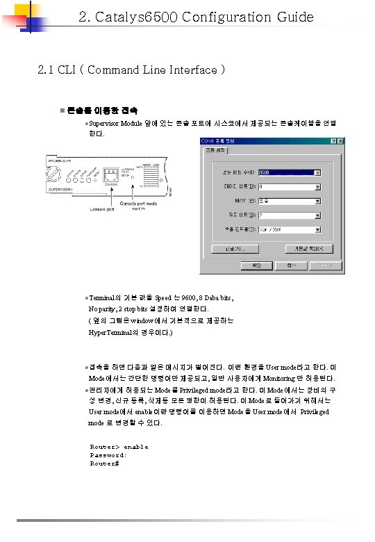
2. 2 초기 스위치 설정 n Native IOS의 특징 l 6500은 두 종류의 IOS(Hybrid IOS, Native IOS)가 있으며 여기서는 Native IOS만 설 명한다. l 모든 port가 Layer 3 routed port인터페이스로 기본 설정되어 있다. l Layer n 3의 configuration 방법은 일반 라우터의 ios와 동일함. Global Parameters 설정 절차 1. 초기에 boot parameter를 설정하지 않으면 rommon. > boot 명령어를 사용한다. rommon 1 > boot slot 0: c 6 sup 22 -jsv-mz. 121 -5 c. EX. bin Self decompressing the image : ################################################################################ ######################################## [OK] Restricted Rights Legend Use, duplication, or disclosure by the Government is subject to restrictions as set forth in subparagraph (c) of the Commercial Computer Software - Restricted 2. 어떠한 설정도 되어 있지 않으므로 다이얼로그 모드가 나타난다. Yes를 선택하면 아래와 같이 나타나다. --- System Configuration Dialog -- Continue with configuration dialog? [yes/no]: y At any point you may enter a question mark '? ' for help. Use ctrl-c to abort configuration dialog at any prompt. Default settings are in square brackets '[]'. Basic management setup configures only enough connectivity for management of the system, extended setup will ask you to configure each interface on the system Would you like to enter the initial configuration dialog? [yes]: no 여기서는 No를 선택하여 직접 환경설정을 하는 것으로 한다. 3. Privileged EXEC 모드로 진입하여 환경설정을 한다. 설정의 변경은 Privileged 모 드에서만 가능하다. Router> enable Router#
4. 프롬프트# 에서 configure terminal을 입력하면 global configuration 모드로 진입 한다. Router# configure terminal Enter configuration commands, one per line. End with CNTL/Z. Router(config)# Global configuration 모드에서 진입한 후 interface 모드나 line 모드로 진입할 수 있다. Router(config)# interface fastethernet 5/1 Router(config-if)# 5. 환경을 저장한다. 그 전에 설정 내용을 확인하기 위하여 현재 running configuration을 아래와 같이 볼 수 있다. Router# show running-config Building configuration. . . Current configuration: Current configuration : 3441 bytes ! version 12. 1 service timestamps debug datetime localtime service timestamps log datetime localtime no service password-encryption ! hostname Router ! boot buffersize 522200 boot system flash slot 0: c 6 sup 22 -jsv-mz. 121 -5 c. EX. bin bootldr bootflash: c 6 msfc 2 -boot-mz. 121 -3 a. E 4 enable password lab ! redundancy main-cpu auto-sync standard ip subnet-zero no ip finger ! cns event-service server ! <. . . output truncated. . . > line con 0 exec-timeout 0 0 transport input none line vty 0 4 exec-timeout 0 0 password lab login transport input lat pad mop telnet rlogin udptn nasi 저장을 하기 위하여서는 아래와 같은 명령어를 사용한다. Router# copy running-config startup-config
n Static 경로 설정 l 텔넷 세션이나 SNMP 적용을 위하여서는 IP address와 라우팅 경로 설정이 필요하다. 이때 static 경로 설정을 위한 방법은 아래와 같다. Command Purpose Step 1 Router(config)# ip route dest_IP_address mask {forwarding_IP | vlan_ID} static route 설정 Step 2 Router# show running-config static route 설정 확인 Router# configure terminal Enter configuration commands, one per line. End with CNTL/Z. Router(config)# ip route 171. 10. 5. 10 255 172. 20. 3. 3 5 Router(config)# end Router# l Running configuration에서 확인을 하면 아래와 같다. Router# show running-config Building configuration. . <. . . output truncated. . . >. ip default-gateway 172. 20. 52. 35 ip classless ip route 171. 10. 5. 10 255 172. 20. 3. 35 no ip http server ! l Static 경로를 Vlan 으로 설정하면 아래와 같다. Router# configure terminal Router(config)# ip route 171. 20. 5. 3 255 vlan 1 Router(config)# end Router# show running-config Building configuration. . <. . . output truncated. . . >. ip default-gateway 172. 20. 52. 35 ip classless ip route 171. 20. 52. 3 255 Vlan 1 no ip http server !
n Password 설정 l 보안을 위하여 Password 설정이 필요하다. l Static Enable Password 설정 User EXEC 모드에서 Privileged EXEC 모드로 진입하기 위한 password 설정으로 Encryption이 안 되는 단점이 잇다. Command Purpose Router(config)# enable password privileged EXEC mode로 진입하기 위한 새로운 패스워드나 기존의 패스워드를 바꿀 때 사용 Router# configure terminal Router(config)# enable password lab Router(config)# l Enable Secret 명령어를 사용하면 password 가 Encyption이 된다. enable password 와 마찬가지로 privileged exec 모드로 진입하며, enable password와 같 이 설정되어 있으면 우선한다. Command Purpose Router(config)# enable password [level] {password | encryption-type encryptedpassword} the privileged EXEC mode로의 패스워드 설정 Router(config)# enable secret [level] {password | encryption-type encryptedpassword} Encryption을 이용하여 패스워드가 보이지 않도 록 설정 ( 만약 enable password 와 enable secret 명령어가 설정되어 있으면 enable secret 이 우선한다. ) l 설정되어 있는 모든 password 를 encryption 하기를 원한다면 다음과 같이 한다. Command Purpose Router(config)# service password-encryption 패스워드를 encryption 한다. l Line Password 설정 Console이나 Telnet 접속을 위한 Line Password 설정은 다음과 같다. Command Purpose Router(config-line)# password 라인모드로 진입하기 위한 패스워드 설정
n Password Recovery l Password 를 복구하기 위한 절차는 아래와 같다. Step 1 Step 2 Step 3 Step 4 Step 5 Step 6 Step 7 콘솔을 연결한다. Configuration 을 읽지 않고 부팅하도록 레지스터리를 수정한다. 스위치를 재부팅한다. Enable(Previliged) 모드로 진입한다. 패스워드 설정 상태를 보고 바꾸든지, 새로운 패스워드를 설정한다. 원래의 레지스터리로 수정한고, 저장한다. 스위치를 재 부팅한다. l Step 2를 위한 rommon> 모드로 가기위하여서는 Break 신호를 보내야 하며 Ctrl-break 나 Alt_B 를 사용한다. n 시스템 이미지 지정 l 부팅 이미지를 설정 파일에 지정한다. 이때 sup-bootlfash: 와 slot 0: 에 저장하도록 한다. l boot loader 이미지의 경우는 bootflash: 에 저장 한다. l boot 정보를 확인 하기 위하여 아래와 같은 명령어를 사용한다. Router# show bootvar BOOT variable = sup-bootflash: c 6 sup-js-mz. 120 -7. XE. bin, 1; CONFIG_FILE variable does not exist BOOTLDR variable = bootflash: c 6 msfc-boot-mz. 120 -7. XE. bin Configuration register is 0 x 0 n 이미지 파일 복사 l copy 명령어를 이용하여 Active Supervisor에 있는 IOS를 Slave Supervisor로 복사하여 동기화 한다. l IOS image의 복사 방법은 아래와 같다. Router# copy source_device: source_filename slavesup-bootflash: target_filename l Bootloader에 사용되는 Rx-boot image 복사 방법은 아래와 같다. Router# copy source_device: source_filename slavebootflash: target_filename
2. 3 RPR and RPR+ Supervisor Engine Redundancy 설정 n RPR and RPR+ l 12. 1. 13(E) 이후의 IOS에서 지원 l 고 가용성을 위한 Feature n RPR 특성 l Active와 Redundant supervisor 엔진 간 auto-startup 과 bootvar 동기화 l Active 와 Redundant 상호 신호를 통하여 상태 감시 l 60초 간격으로 클럭 동기화 l redundant supervisor의 이미지만 부팅된 상태 l redundant supervisor 엔진의 두개의 GE 포트는 redundncy와 상관없이 Active n RPR Trigger 조건 l Clock 동기화 실패 l MSFC 또는 PFC 동작 불 l 강제 전환 n Redundant supervisor 가 Active 시 RPR 동작 l 모든 인터페이스 모듈은 다시 Power Up l MSFC 상의 Subsybytem( Ex, Layer 2 와 Layer 3 프로토콜 )이 올라온다. l ACL 이 supervisor 엔진의 하드웨어에 적용 l 전환될 때는 트래픽 유실이 발생한다. n RPR+ 특성 l 전환 시간이 RPR 보다 빠르다, 설정내용에 따라 약 30~60초 정도 l running-configuration도 동기화 되어, 인터페이스 모듈은 다시 reload 되지 않는다. l OIR 이벤트 동기화 l 명령어로 전환 가능, command : redundancy force-switchover n RPR Trigger 조건 l Clock 동기화 실패 l MSFC 또는 PFC 동작 불 l 강제 전환 .
n RPR+ 제약 사항 l RPR+ 모드에서는 vlan database 에서의 configuration을 지원하지 않는다. l SNMP를 이용하여 변경된 설정은 동기화 되지 않는다. l 60초 간격으로 클럭 동기화 l Active와 Redundancy 의 전환 시간 동안 트래픽 유실 발생 l Active와 Redundancy는 동일한 IOS를 사용하여야 한다. l Active와 Redundancy 의 전환 시 FIB(Forwarding Information Base) 테이블의 내용이 없 어지므로 다시 라우팅 테이블을 생성하는 동안 routed 트래픽은 유실된다 l Static으로 설정된 경로는 설정파일에 저장되어 있으므로 변화가 없다. l Dynamic 하게 바뀌어지는 내용(BGP Session 등)은 동기화 되지 않는다. l core dum가 설정되어 있으면, 장애 시 core dump 후에 Redundancy 가 Active가 되므로 약 15분 정도가 소요된다. l 동기화가 이루어지는 동안 설정을 변경하면 반영되지 않고 메시지가 나타난다. config mode locked out till standby initializes n RPR 과 RPR+ 설정 Command Purpose Step 1 Router(config)# redundancy configuration mode로 진입 Step 2 Router(config-red)# mode { rpr | rpr-plus } RPR 이나 RPR+로 선택하여 설정. 이 모드로 진입하면 redundant supervisor engine 은 reload 되며 RPR 이나 RPR+ 모드로 진입한다. Step 3 Router# show running-config RPR 이나 RPR+ 가 설정되었는지 확인 Step 4 Router# show redundancy states 현재 운용중인 redundancy 모드 확인 Router> enable Router# configure terminal Enter configuration commands, one per line. End with CNTL/Z. Router(config)# redundancy Router(config-red)# mode rpr-plus Router(config-red)# ^Z Router# show redundancy states my state = 13 -ACTIVE peer state = 1 -DISABLED Mode = Simplex Unit = Primary Unit ID = 1 Redundancy Mode (Operational) = Route Processor Redundancy Plus Redundancy Mode (Configured) = Route Processor Redundancy Plus Split Mode = Disabled Manual Swact = Disabled Reason: Simplex mode Communications = Down Reason: Simplex mode
n Supervisor 엔진 설정내용 동기화 l 기본적으로 startup-config 와 config-register는 동기화 된다. l bootvar는 기본적으로 동기화 되지 않으며 원할 경우 설정하여야 한다 l 전환 시 Redundancy는 running config를 이용한다. Command Purpose Step 1 Router(config)# redundancy configuration 모드로 진입 Step 2 Router(config-red)# main-cpu configuration submode로 진입 Step 3 Router(config-r-mc)# auto-sync {startupconfig | config-register | bootvar | standard } configuration 요소들을 상호 동기화 Step 4 Router(config-r-mc)# end privileged EXEC mode로 복귀 Step 5 Router# copy running-config startup-config 강제적으로 현재 운용중인 설정환경을 NVRAM에 저장한다. 이때 redundant supervisor의 NVRAM 도 같이 동기화 된다. Router(config)# redundancy Router(config-red)# main-cpu Router(config-r-mc)# auto-sync standard Router(config-r-mc)# auto-sync bootvar Router(config-r-mc)# end Router# copy running-config startup-config Router# show redundancy states my state = 13 -ACTIVE peer state = 8 -STANDBY HOT Mode = Duplex Unit = Primary Unit ID = 1 Redundancy Mode (Operational) = Route Processor Redundancy Plus Redundancy Mode (Configured) = Route Processor Redundancy Plus Split Mode = Disabled Manual Swact = Enabled Communications = Up client count = 11 client_notification_TMR = 30000 milliseconds keep_alive TMR = 9000 milliseconds keep_alive count = 0 keep_alive threshold = 18 RF debug mask = 0 x 0
2. 4 인터페이스 설정 n 인터페이스 l 종류 - Ethernet (ethernet 명령어 사용) - Fast Ethernet(fastethernet 명령어 사용) - Gigabit Ehternet(gigabitethernet 명령어 사용) - 10 -Gigabit Ethernet(tengigabitethernet 명령어 사용) l 슬롯 넘버 : Catalyst 6500은 위에서 아래로 1번 부터 시작 l 포트 넘버 : 왼쪽에서 오른쪽으로 1번 부터 시작 n Interface 명령어 사용 l Interface mode로 진입은 global configuration 모드에서 가능 Router# configure terminal Enter configuration commands, one per line. End with CNTL/Z. Router(config)# l 설정하고자 하는 인터페이스 Type 과 Slot/Port 를 지정한다 Router(config)# interfaces fastethernet 5/1 Router(config-if)# l 해당 인터페이스에 필요한 사항을 설정한다. l show interface 명령어를 이용하여 해당 인터페이스를 확인한다. Router# show interfaces fastethernet 5/48 Fast. Ethernet 5/48 is up, line protocol is up Hardware is C 6 k 100 Mb 802. 3, address is 0050. f 0 ac. 3083 (bia 0050. f 0 ac. 3083) Internet address is 172. 20. 52. 18/27 MTU 1500 bytes, BW 100000 Kbit, DLY 100 usec, reliability 255/255, txload 1/255, rxload 1/255 Encapsulation ARPA, loopback not set Keepalive set (10 sec) Half-duplex, 100 Mb/s ARP type: ARPA, ARP Timeout 04: 00 Last clearing of "show interface" counters never Input queue: 0/75/0/0 (size/max/drops/flushes); Total output drops: 0 Queueing strategy: fifo Output queue : 0/40 (size/max) 5 minute input rate 1000 bits/sec, 1 packets/sec 5 minute output rate 1000 bits/sec, 1 packets/sec 4834677 packets input, 329545368 bytes, 0 no buffer Received 4796465 broadcasts, 0 runts, 0 giants, 0 throttles 0 input errors, 0 CRC, 0 frame, 0 overrun, 0 ignored 0 input packets with dribble condition detected 51926 packets output, 15070051 bytes, 0 underruns 0 output errors, 2 collisions, 2 interface resets 0 babbles, 0 late collision, 0 deferred 0 lost carrier, 0 no carrier 0 output buffer failures, 0 output buffers swapped out
n Range를 정하여 인터페이스 설정 l 동일한 설정을 여러 인터페이스에 적용할 때 편리 Command Purpose Router(config)# interface range {{vlan_ID [, vlan_ID - vlan_ID]} | {type slot/port - port [, type slot/port - port]} | {macro_name [, macro_name]}} 설정할 인터페이스의 범위를 선 택한다. Router(config)# no interface range {{vlan_ID [, vlan_ID - vlan_ID]} | {macro_name [, macro_name]}} 제거할 VLAN의 범위를 선택한 다. l 대쉬 기호 앞과 뒤에 space 필요 l 최대 5개의 콤머(, ) 사용 가능 l 콤머(, ) 뒤에는 space가 있어도 되고 없어도 된다. l interface range를 사용할 수 있는 인터페이스는 다음과 같으며, IOS에 따라 다르다. - ethernet, fastethernet, gigabitethernet, tengigabitethernet vlan Router(config)# interface range fastethernet 5/1 - 5 Router(config-if)# no shutdown Router(config-if)# *Oct 6 08: 24: 35: %LINK-3 UPDOWN: Interface Fast. Ethernet 5/1, changed state to up *Oct 6 08: 24: 35: %LINK-3 UPDOWN: Interface Fast. Ethernet 5/2, changed state to up *Oct 6 08: 24: 35: %LINK-3 UPDOWN: Interface Fast. Ethernet 5/3, changed state to up *Oct 6 08: 24: 35: %LINK-3 UPDOWN: Interface Fast. Ethernet 5/4, changed state to up *Oct 6 08: 24: 35: %LINK-3 UPDOWN: Interface Fast. Ethernet 5/5, changed state to up *Oct 6 08: 24: 36: %LINEPROTO-5 UPDOWN: Line protocol on Interface Fast. Ethernet 5/ 3, changed state to up *Oct 6 08: 24: 36: %LINEPROTO-5 UPDOWN: Line protocol on Interface Fast. Ethernet 5/ 4, changed state to up Router(config-if)# * Link state 메시지(LINK-3 -UPDOWN and LINEPROTO-5 -UPDOWN)은 기본적으로 비 활성화 되어 있으므로 이러한 link 정보를 활성화 하기 위하여서는 interface command인 Logging event link status 를 사용하면 된다.
n Speed 와 Duplex 설정 l 기본적으로 auto로 설정이 되어있으며, 권고하는 사항이다. l 장비간 인터페이스간 auto-negotiation이 되지 않을 경우에는 수동으로 설정 l speed와 duplex를 설정하면, 대응되는 장비의 speed와 duplex도 수정하여야 한다. l 10 -Gigabit Ethernet 과 Gigabit Ethernet은 Full Duplex만 지원한다. Step 1 Step 2 Step 3 Command Purpose Router(config)# interface fastethernet slot/port 설정한 이더넷 포트 선정 Router(config-if)# speed {10 | 1000 | auto} 스피드 설정. Router(config-if)# no speed 기본설정인 auto speed 환경으로 원복 되어 진다. Router(config-if)# duplex [auto | full | half] 듀플렉스 모드 설정 Router(config-if)# no duplex 기본전인 auto duplex 환경으로 원복 되어 진다. n Gigabit Ethernet에서의 Link Negotiation l Link negotiation 을 통하여 flow-control parameters, remote fault 정보, duplex 정보르 ㄹ 교환한다. l Link negotiation은 기본적으로 활성화 되어 있다. l 양 포트는 동일하게 설정도어 있어야 한다. 만약 설정에 차이가 있으면 정상동작 하 지 않고 아래와 같이 나타난다. Link Negotiation State Link Status Local Port Remote Port Off Up Up On On Up Up Off On Up Down On Off Down Up Step 1 Step 2 Command Purpose Router(config)# interface gigabitethernet slot/port 설정할 인터페이스 선정 Router(config-if)# speed nonegotiate 링크 negotiation 비활성화 Router(config-if)# no speed nonegotiate 기본적인 환경으로 원복 (link negotiation enabled). Router(config)# interface gigabitethernet 5/4 Router(config-if)# no speed nonegotiate
n Speed 와 Duplex 모드 Display l 설정 상태를 보기 위하여 show interface 명령어를 이용한다. Command Purpose Router# show interfaces type slot/port 스피드와 듀플렉스 모드에 설정 확인. type = ethernet, fastethernet, gigabitethernet, or tengigabitethernet Router# show interfaces fastethernet 5/4 Fast. Ethernet 5/4 is up, line protocol is up Hardware is Cat 6 K 100 Mb Ethernet, address is 0050. f 0 ac. 3058 (bia 0050. f 0 ac. 3058) MTU 1500 bytes, BW 100000 Kbit, DLY 100 usec, reliability 255/255, txload 1/255, rxload 1/255 Encapsulation ARPA, loopback not set Keepalive set (10 sec) Full-duplex, 100 Mb/s ARP type: ARPA, ARP Timeout 04: 00 Last input 00: 33, output never, output hang never Last clearing of "show interface" counters never Queueing strategy: fifo Output queue 0/40, 0 drops; input queue 0/75, 0 drops 5 minute input rate 0 bits/sec, 0 packets/sec 5 minute output rate 0 bits/sec, 0 packets/sec 1238 packets input, 273598 bytes, 0 no buffer Received 0 broadcasts, 0 runts, 0 giants, 0 throttles 0 input errors, 0 CRC, 0 frame, 0 overrun, 0 ignored 0 input packets with dribble condition detected 1380 packets output, 514382 bytes, 0 underruns 0 output errors, 0 collisions, 2 interface resets 0 babbles, 0 late collision, 0 deferred 0 lost carrier, 0 no carrier 0 output buffer failures, 0 output buffers swapped out Router# n 인터페이스 Description l 운용자가 관리에 용이하기 위하여 인터페이스에 대한 정보를 입력한다. l show configuration, show running-configuration, show interface 로 확인 가능. Command Purpose Router(config-if)# description string 인터페이스에 대한 정보 입력. Router(config-if)# no description 삭제 Router(config)# interface fastethernet 5/5 Router(config-if)# description Channel-group to "Marketing"
n 인터페이스 Counter 초기화 l show interface 에서의 counter를 초기화 Command Purpose Router# clear counters {{vlan_ID} | {type 1 slot/port} | {port-channel_ID}} 카운터 제거 type = ethernet, fastethernet, gigabitethernet, or tengigabitethernet Router# clear counters fastethernet 5/5 Clear "show interface" counters on this interface [confirm] y Router# *Sep 30 08: 42: 55: %CLEAR-5 COUNTERS: Clear counter on interface Fast. Ethernet 5/5 n 인터페이스 Reset l 인터페이스의 reset Command Purpose Router# clear interface type 1 slot/port 인터페이스 리셋 type = ethernet, fastethernet, gigabitethernet, or tengigabitethernet Router# clear interface fastethernet 5/5 Router# n 인터페이스 Shutdown 과 Restarting l 인터페이스의 모든 기능을 정지하기 위하여 shutdown 명령어 사용. l 다시 인터페이스를 활성화 하기 위하여 no shutdown 명령어 사용. Command Purpose Step 1 Router(config)# interface {{vlan_ID} | {type 1 slot/port} | {port-channel_ID}} 설정할 인터페이스 선택 Step 2 Router(config-if)# shutdown Shuts down. Step 3 Router(config-if)# no shutdown 다시 활성화 Router(config)# interface fastethernet 5/5 Router(config-if)# shutdown Router(config-if)# *Sep 30 08: 33: 47: %LINK-5 CHANGED: Interface Fast. Ethernet 5/5, changed state to administratively d own Router(config-if)# no shutdown Router(config-if)# *Sep 30 08: 36: 00: %LINK-3 UPDOWN: Interface Fast. Ethernet 5/5, changed state to up
n Default Layer 2 LAN 설정 l Catalyst 6500에 설정된 기본 설정 Feature Default Interface mode: • Before entering the switchport Layer 3 (unconfigured) 즉 기본적으로 Routed Interface 로 설정되어 있다. command • After entering the switchport mode dynamic desirable command Trunk encapsulation switchport trunk encapsulation negotiate • With Release 12. 1(13)E and later releases, VLANs 1 to 4094, except Allowed VLAN range reserved VLANs • With 12. 1 E releases earlier than Release 12. 1(13)E, VLANs 1 to 1005 즉 12. 1(13)E 이상의 버전을 사용하여야 VLAN의 수를 늘일 수 있다. VLAN range eligible for pruning VLANs 2 to 1001 Default VLAN (for access ports) VLAN 1 Native VLAN (for 802. 1 Q trunks) VLAN 1 Spanning Tree Protocol (STP) Enabled for all VLANs STP port priority 128 • 100 for 10 -Mbps Ethernet LAN ports • 19 for 10/100 -Mbps Fast Ethernet LAN ports • 19 for 100 -Mbps Fast Ethernet LAN ports • 4 for 1, 000 -Mbps Gigabit Ethernet LAN ports • 2 for 10, 000 -Mbps 10 -Gigabit Ethernet LAN ports STP port cost n LAN 인터페이스 제한 조건 l 10 Gigabit Ethernet은 ISL encapsulation을 지원하지 않는다. l Non-Cisco Switch와의 Spanning Tree는 VLAN마다 지원하지 않고 하나만 지원한다. n LAN 설정 안 l 802. 1 q 트렁크 서정시 양쪽의 native vlan이 동일한지 확인하여야 한다. 만약 native vlan이 틀리면 stp loop가 발생 할 수 있다. l 802. 1 q 트렁크의 VLAN에 대하여 Spanning Tree를 비활성화 하기를 원한다면 Native VLAN 과 나머지 VLAN에 대하여 모두 적용하든지, 적어도 Native VLAN만은 활성화 하 도록 한다. 이는 stp loop 발생 가능성 때문이다. l STP 를 비 활성화 할 때에는 꼭 물리적인 loop가 없는 지 확인한다. l Non Cisco 스위치와 Trunk 연결시는 꼭 802. 1 q를 사용한다.
n Layer 2 인터페이스 설정 l 설정 내용을 default 설정으로 원복하기를 원할 때는 default interface {ethernet | fastethernet | gigabitethernet | tengigaethernet} slot/port l switchport 명령어를 입력하면, switchport mode dynamic desirable이 기본적으로 설정 되어 상대 스위치가 trunk 가 on 되어 있거나, auto로 설정되면 트렁크 인터페이스가 된 다. 그러나 상대 스위치가 기본인 desirable로 설정되어 있으면 트렁크가 되지 않는다. l switchport 명령어를 입력하면, 트렁크 encapsulation은 기본적으로 negotiation모드가 되어서 먼저 ISL encapsulation으로 동작을 하고, ISL을 지원하지 않으면 802. 1 q로 동작 한다. Command Purpose Step 1 Router(config)# interface type 1 slot/port 인터페이스 선정 Step 2 Router(config-if)# shutdown (Optional) 설정이 완료되기 전까지는 트래픽이 흐르 지 않도록 인터페이스 shutdown Router(config-if)# switchport 기본적으로 Layer 3 Routed 인터페이스로 설정되어 있으므로, switchport라는 명령어를 입력하여야만 Layer 2 Switched 인터페이스가 된다. 이 명령어 입력 이후에야, 다른 switchport 관련 명령어를 입력할 수 있다. Router(config-if)# no switchport Layer 2 LAN 관련 설정 삭제 Step 4 Router(config-if)# no shutdown 인터페이스 활성화. (Required only if you shut down the interface. ) Step 5 Router(config-if)# end configuration mode를 빠져나감 Step 6 Router# show running-config interface [type slot/port] 해당 인터페이스의 running configuration 을 보여줌 Step 7 Router# show interfaces [type slot/port] switchport 해당 인터페이스의 switch port configuration을 보여 줌 Step 8 Router# show interfaces [type slot/port] trunk 해당 인터페이스의 trunk configuration을 보여줌 Step 3 type = ethernet, fastethernet, gigabitethernet, or tengigabitethernet n LAN 인터페이스 트렁크 설정 l ISL 또는 802. 1 q 트렁크를 지정하여 설정 할 수 있으며, negotiation (auto)로 설정 가능 하다. Command Purpose Router(config-if)# switchport trunk encapsulation {isl | dot 1 q | negotiate} (Optional) 트렁크 모드에 다한 encapsulation을 ISL 이나 802. 1 Q trunk로 설정 Note switchport mode trunk 명령어를 입력하기 위 하여서는 사전에 encapsulation 설정을 하여야 한다. Router(config-if)# no switchport trunk encapsulation default trunk encapsulation mode 로 원복(negotiate).
DTP(Dynamic Trunking Protocol) 설정 n l 인터페이스를 트렁트로 고정하여 설정하지 않고, auto 나 desirable 옵션을 이용하여 상대편 스위치의 설정 상태에 따라서 유동적으로 변경됨 Command Purpose Router(config-if)# switchport mode dynamic {auto | desirable} (Optional) DTP를 사용하도록 설정. Router(config-if)# no switchport mode 기본 설정으로 원복 (switchport mode dynamic desirable). DTP(Dynamic Trunking Protocol)를 이용하지 않는 설정 n l 상대편의 상태에 상관없이 인터페이스를 트렁크로 고정 l DTP를 전혀 사용하지 않도록 설정 가능 l switchport mode trunk 입력 전에 encapsulation을 먼저 설정하여야 한다 Step 1 Step 2 Command Purpose Router(config-if)# switchport mode trunk (Optional) 동적으로 변동 없이 trunk가 되도록 설정. Router(config-if)# no switchport mode 기본 설정으로 원복 (switchport mode dynamic desirable). Router(config-if)# switchport nonegotiate (Optional) DTP를 사용하지 않도록 설정 Router(config-if)# no switchport nonegotiate 인터페이스에 DTP 활성화 n Default VLAN 설정 l 인터페이스는 트렁크 와 Access 두가지 형태가 있다. l 트렁크로 동작하지 않고 Access 로만 동작할 때 인터페이스의 VLAN Command Purpose Router(config-if)# switchport access vlan_ID (Optional) 인터페이스가 트렁크가 아니었을 때의 인 터페이스에 대하여 VLAN 할당 • 12. 1(13)E 이후에는 1 ~ 4094까지의 VLAN을 설정 강능 • Release 12. 1(13)E 전의 버전일 경우는 1 ~ 1005의 VLAN을 사용가능 Router(config-if)# no switchport access vlan default value (VLAN 1) 로 복원
n 802. 1 q Native VLAN 설정 l 802. 1 q에서 사용되는 Native VLAN 설정 l access VLAN을 설정하였다고 하여 자동적으로 Native VLAN이 되는 것은 아니다. Command Purpose Router(config-if)# switchport trunk native vlan_ID (Optional) 802. 1 Q native VLAN 설정 Router(config-if)# no switchport trunk native vlan Native VLAN을 default 값 (VLAN 1)으로 설정 n 트렁크상의 Allowed VLAN 설정 l 트렁크상에서 허용하는 VLAN 을 설정한다. l Allowed VLAN을 설정하지 않으면 트렁크에 설정된 모든 VLAN을 허용한다 l 12. 1(11 b)E 이후 버전부터는 VLAN 1을 허용하지 않을 수 있다. l 802. 1 q에서는 VLAN 1을 통하여, CDP(Cisco Discovery Protocol), VTP(VLAN Trunking Protocol), PAg. P(Prot Aggregation Protocol), 과 DTP(Dynamic Trunking Protocol) 정보를 주고 받는다. Command Purpose Router(config-if)# switchport trunk allowed vlan {add | except | none | remove} vlan [, vlan[, . . . ]] (Optional) 트렁크상에 허용되는 VLAN의 ID Router(config-if)# no switchport trunk allowed vlan default 값 (all VLANs allowed) 으로 원복 n Prune 인식 VLAN 선별 설정 l Prune은 필요 없는 Broadcast 같은 트래픽이 Trunk를 통하여 스위치로 전달되지 않도 록 한다. l 자세한 내용은 6장 VTP 설정을 참조 하여 이장에서는 인터페이스에 Prune 설정 방법 에 대하여 설명한다. l 기본적으로 모든 VLAN은 Prune이 설정되어 있다. l VLAN 1 은 Prune 되지 않는다. Command Purpose Router(config-if)# switchport trunk pruning vlan {none |{{add | except | remove} vlan[, . . . ]]}} (Optional) 트렁크상의 prune-eligible VLAN 등록 Router(config-if)# no switchport trunk pruning vlan 기본 값으로(all VLANs prune-eligible) 원복
n 트렁크 설정 완료 l 인터페이스를 활성화 함으로써 설정을 완료한다. Command Purpose Step 1 Router(config-if)# no shutdown 인터페이스 활성화 (Required only if you shut down the interface. ) Step 2 Router(config-if)# end configuration mode를 나감 n 트렁크 설정 확인 l show 명령어를 사용하여 트렁크의 설정 상태를 확인한다. Command Purpose Step 1 Router# show running-config interface type 1 slot/port 인터페이스의 running configuration 조회 Step 2 Router# show interfaces [type slot/port] switchport 인터페이스의 switch port configuration 조회 Step 3 Router# show interfaces [type slot/port] trunk 인터페이스의 트렁크 configuration 조회 Router# configure terminal Enter configuration commands, one per line. End with CNTL/Z. Router(config)# interface fastethernet 5/8 Router(config-if)# shutdown Router(config-if)# switchport mode dynamic desirable Router(config-if)# switchport trunk encapsulation dot 1 q Router(config-if)# no shutdown Router(config-if)# end Router# exit Router# show running-config interface fastethernet 5/8 Building configuration. . . Current configuration: ! interface Fast. Ethernet 5/8 no ip address switchport trunk encapsulation dot 1 q end Router# show interfaces fastethernet 5/8 switchport Name: Fa 5/8 Switchport: Enabled Administrative Mode: dynamic desirable Operational Mode: trunk Administrative Trunking Encapsulation: negotiate Operational Trunking Encapsulation: dot 1 q Negotiation of Trunking: Enabled Access Mode VLAN: 1 (default) Trunking Native Mode VLAN: 1 (default) Trunking VLANs Enabled: ALL Pruning VLANs Enabled: ALL
n Layer 2 Access 인터페이스 설정 l 인터페이스에 VLAN을 할당. l 스위치에 존재하지 않는 VLAN을 할당하면 shutdown 상태가 된다. Command Purpose Step 1 Router(config)# interface type 인터페이스 선정. slot/port Step 2 Router(config-if)# shutdown (Optional) 설정이 완료될 때 까지 트래픽이 흐르는 것 을 방지 Step 3 Router(config-if)# switchport 기본적으로 Layer 3 Routed 인터페이스로 설정되어 있으므로, switchport라는 명령어를 입력하여야만 Layer 2 Switched 인터페이스가 된다. 이 명령어 입력 이후에야, 다른 switchport 관련 명령어를 입력할 수 있다 Step 4 Router(config-if)# no switchport Layer 2 LAN 관련 설정 삭제. Router(config-if)# switchport mode access 인터페이스를 Layer 2 access port로 설정 Router(config-if)# no switchport mode 기본적인 인터페이스의 (switchport mode dynamic desirable) 상태로 원복 Router(config-if)# switchport access vlan_ID (Optional) 인터페이스가 트렁크가 아니었을 때의 인 터페이스에 대하여 VLAN 할당 • 12. 1(13)E 이후에는 1 ~ 4094까지의 VLAN을 설정 가능 • Release 12. 1(13)E 전의 버전일 경우는 1 ~ 1005의 VLAN을 사용가능 Router(config-if)# no switchport access vlan default VLAN (VLAN 1)으로 원복 Step 7 Router(config-if)# no shutdown 인터페이스 활성화 (Required only if you shut down the interface. ) Step 8 Router(config-if)# end configuration mode를 나감 Step 9 Router# show running-config interface [type slot/port] 인터페이스의 running configuration 조회 Step 10 Router# show interfaces [type slot/port] switchport 인터페이스의 switch port configuration 조회 Step 5 Step 6
Router# configure terminal Enter configuration commands, one per line. End with CNTL/Z. Router(config)# interface fastethernet 5/6 Router(config-if)# shutdown Router(config-if)# switchport mode access Router(config-if)# switchport access vlan 200 Router(config-if)# no shutdown Router(config-if)# end Router# exit Router# show running-config interface fastethernet 5/6 Building configuration. . . ! Current configuration: interface Fast. Ethernet 5/6 no ip address switchport access vlan 200 switchport mode access end Router# show interfaces fastethernet 5/6 switchport Name: Fa 5/6 Switchport: Enabled Administrative Mode: static access Operational Mode: static access Administrative Trunking Encapsulation: negotiate Operational Trunking Encapsulation: native Negotiation of Trunking: Enabled Access Mode VLAN: 200 (VLAN 0200) Trunking Native Mode VLAN: 1 (default) Trunking VLANs Enabled: ALL Pruning VLANs Enabled: ALL Router#
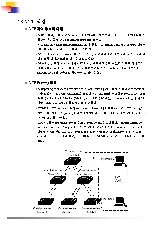
l 그림 6 -2는 VTP pruning 활성화된 network switch를 보여준다. Switch 1에서 Broadcast traffic은Red VLAN의 traffic이 link 감지(Switch 2의 port 5와 Switch 4의 port 4)되어 차단 되기 때문에 Switch 3, 5 와 6에 전달되지 않는다. 그림 6 -2 Flooding Traffic with VTP Pruning l 전체 management domain을 위해 VTP server에서 pruning하여 VTP pruning 할 수 있다. VTP pruning은 그것을 활성화한 몇 초 후에 적용된다. 기본적으로 VLAN 2부터 1000까 지가 pruning 적당하다. VTP pruning traffic은 pruning-ineligible VLAN에 의해서 차단되 지 않는다. VLAN 1은 언제나 pruning 자격이 없다. 즉, VLAN 1의 traffic은 차단할 수 없 다. l Trunking LAN port에서 VTP pruning 설정은 switchport trunk pruning vlan 명령어를 이용한다. VTP pruning은 LAN port를 trunking 할 때 적용한다.
n n VTP 초기 설정 Feature Default Value VTP domain name Null VTP mode Server VTP version 2 enable state Version 2 is disabled VTP password None VTP pruning Disabled VTP 패스워드 설정 l 이 명령은 global parameter 에서 설정한다. Command Purpose Router(config)# vtp password_string Password 설정, VTP domain을 위한 8개 부터 64개 까지 길이 의 문자 Router(config)# no vtp password Password 제거 l Release 12. 1(13)E 이후 버전에서 VTP Password 설정은 아래와 같다. Router# configure terminal Router(config)# vtp password WATER Setting device VLAN database password to WATER. Router# l 모든 버전에서 VTP Password 설정은 아래와 같다. Router# vtp password WATER Setting device VLAN database password to WATER. Router# n VTP Pruning 설정 l 관리 도메인에서 VTP pruning 설정 방법 Step 1 Step 2 Command Purpose Router(config)# vtp pruning Management domain에서 VTP pruning 활성화 Router(config)# no vtp pruning Management domain에서 VTP pruning 비활성화 Router# show vtp status Configuration 확인
l Release 12. 1(13)E 이후 버전에서 VTP pruning 설정은 아래와 같다. . Router# configure terminal Router(config)# vtp pruning Pruning switched ON l 모든 버전에서 VTP pruning 설정은 아래와 같다. Router# vtp pruning Pruning switched ON l 설정 확인 방법 Router# show vtp status | include Pruning VTP Pruning Mode: Enabled Router# n VTP Version 2 설정 l VTP version 2 을 지원하는 network device들은 기본적으로 VTP version 2가 비활성화 되 어있다. VTP version 2를 사용하고자 할 때에는 VTP 도메인에 있는 VTP version 2 설정가 능한 network device를 VTP version 2 로 설정한다. l VTP version 1 과 VTP version 2 는 동일 VTP 도메인 network device에서 호환되지 않는다. VTP 도메인에 있는 모든 network device는 동일한 VTP version 을 사용해야 한다. VTP 도메인에 있는 모든 network device가 version 2를 지원하지 않으면 VTP version 2를 사용 할 수 없다. l VTP version 2 설정 Step 1 Step 2 Command Purpose Router(config)# vtp version {1 | 2} VTP version 2 활성화 Router(config)# no vtp version 초기버전 복귀 (VTP version 1). Router# show vtp status Configuration 확인 l Release 12. 1(13)E 이후 버전에서 VTP Password 설정은 아래와 같다. Router# configure terminal Router(config)# vtp version 2 V 2 mode enabled. Router(config)# l 모든 버전에서 VTP Password 설정은 아래와 같다. Router# vtp version 2 V 2 mode enabled. Router# l 설정 확인 방법 Router# show vtp status | include V 2 VTP V 2 Mode: Enabled Router#
n VTP Mode 설정 l VTP mode 설정 Command Purpose Router(config)# vtp mode {client | server | transparent} VTP mode 설정 Router(config)# no vtp mode VTP초기 복귀 mode (server). Step 2 Router(config)# vtp domain_name (Server mode 선택) VTP domain name 정의, 32개 문자 길이. VTP server mode는 domain name을 요구한다. Switch가 VTP domain trunk 연결을 한다면 switch는 domain 내의 VTP server로 부터 domain name을 학습한다. Step 3 Router(config)# end VLAN configuration mode를 나감 Step 4 Router# show vtp status Configuration 확인 Step 1 l VTP 서버 스위치로 설정할 경우의 예 Router# configure terminal Router(config)# vtp mode server Setting device to VTP SERVER mode. Router(config)# vtp domain Lab_Network Setting VTP domain name to Lab_Network Router(config)# end Router# l VTP 서버 설정 확인의 예 Router# show vtp status VTP Version : 2 Configuration Revision : 255 Maximum VLANs supported locally : 1005 Number of existing VLANs : 35 VTP Operating Mode : Server VTP Domain Name : Lab_Network VTP Pruning Mode : Enabled VTP V 2 Mode : Enabled VTP Traps Generation : Disabled MD 5 digest : 0 x 08 0 x 7 E 0 x 54 0 x. E 2 0 x 5 A 0 x 79 0 x. A 9 0 x 2 D Configuration last modified by 127. 0. 0. 12 at 8 -7 -02 11: 21: 43 Local updater ID is 127. 0. 0. 12 on interface EO 0/0 (first interface found) Router#
l VTP 클라이언트 스위치로 설정할 경우의 예 Router# configure terminal Router(config)# vtp mode client Setting device to VTP CLIENT mode. Router(config)# exit Router# l VTP 클라이언트 설정 확인의 예 Router# show vtp status VTP Version : 2 Configuration Revision : 255 Maximum VLANs supported locally : 1005 Number of existing VLANs : 35 VTP Operating Mode : Client VTP Domain Name : Lab_Network VTP Pruning Mode : Enabled VTP V 2 Mode : Enabled VTP Traps Generation : Disabled MD 5 digest : 0 x 08 0 x 7 E 0 x 54 0 x. E 2 0 x 5 A 0 x 79 0 x. A 9 0 x 2 D Configuration last modified by 127. 0. 0. 12 at 8 -7 -02 11: 21: 43 Router# l 스위치에서 VTP 비활성화 할 경우의 예 Router# configure terminal Router(config)# vtp transparent Setting device to VTP TRANSPARENT mode. Router(config)# end Router# l 스위치에서 VTP 비활성화 확인의 예 Router# show vtp status VTP Version : 2 Configuration Revision : 247 Maximum VLANs supported locally : 1005 Number of existing VLANs : 33 VTP Operating Mode : Transparent VTP Domain Name : Lab_Network VTP Pruning Mode : Enabled VTP V 2 Mode : Disabled VTP Traps Generation : Disabled MD 5 digest : 0 x 45 0 x 52 0 x. B 6 0 x. FD 0 x 63 0 x. C 8 0 x 49 0 x 80 Configuration last modified by 0. 0 at 8 -12 -99 15: 04: 49 Router#
n VTP 통계 표시 l VTP 통계 표시는 VTP 정보를 주고 받은 것과 VTP 에러가 포함된다. Command Purpose Router# show vtp counters Displays VTP statistics l VTP 통계 표시의 예 Router# show vtp counters VTP statistics: Summary advertisements received : 7 Subset advertisements received : 5 Request advertisements received : 0 Summary advertisements transmitted : 997 Subset advertisements transmitted : 13 Request advertisements transmitted : 3 Number of config revision errors : 0 Number of config digest errors : 0 Number of V 1 summary errors : 0 VTP pruning statistics: Trunk Join Transmitted Join Received Summary advts received from non-pruning-capable device ------------------Fa 5/8 43071 42766 5
n VLAN 변수 설정 l VLAN 2에서 1001까지 다음의 변수를 설정할 수 있다. • VLAN name • VLAN type (Ethernet, FDDI network entity title [NET], Tr. BRF, • • • n or Tr. CRF) VLAN state (active or suspended) Security Association Identifier (SAID) Bridge identification number for Tr. BRF VLANs Ring number for FDDI and Tr. CRF VLANs Parent VLAN number for Tr. CRF VLANs Spanning Tree Protocol (STP) type for Tr. CRF VLANs VLAN 기본 설정 l Ethernet VLAN 기본값과 범위 Parameter Default Range VLAN ID 1 1 -4094 VLAN name "default" for VLAN 1 "VLANvlan_ID" for other Ethernet VLANs — 802. 10 SAID 10 vlan_ID 100001 -104094 MTU size 1500 -18190 Translational bridge 1 0 0 -1005 Translational bridge 2 0 0 -1005 VLAN state active, suspend Pruning eligibility VLANs 2 -1001 are pruning eligible; VLANs 1006 -4094 are not pruning eligible. — l FDDI VLAN 기본값과 범위 Parameter Default Range VLAN ID 1002 1 -1005 VLAN name "fddi-default" — 802. 10 SAID 101002 1 -4294967294 MTU size 1500 -18190 Ring number 0 1 -4095 Parent VLAN 0 0 -1005 Translational bridge 1 0 0 -1005 Translational bridge 2 0 0 -1005 VLAN state active, suspend
l Token Ring(Tr. CRF) VLAN 기본값과 범위 Parameter Default Range VLAN ID 1003 1 -1005 VLAN name "token-ring-default" — 802. 10 SAID 101003 1 -4294967294 Ring Number 0 1 -4095 MTU size VTPv 1 default 1500 VTPv 2 default 4472 1500 -18190 Translational bridge 1 0 0 -1005 Translational bridge 2 0 0 -1005 VLAN state active, suspend Bridge mode srb, srt ARE max hops 7 0 -13 STE max hops 7 0 -13 Backup CRF disabled disable; enable l FDDI-Net VLAN 기본값과 범위 Parameter Default Range VLAN ID 1004 1 -1005 VLAN name "fddinet-default" — 802. 10 SAID 101004 1 -4294967294 MTU size 1500 -18190 Bridge number 1 0 -15 STP type ieee auto, ibm, ieee VLAN state active, suspend l. Token Ring(Tr. BRF) VLAN 기본값과 범위 Parameter Default Range VLAN ID 1005 1 -1005 VLAN name "trnet-default" — 802. 10 SAID 101005 1 -4294967294 MTU size VTPv 1 1500; VTPv 2 4472 1500 -18190 Bridge number 1 0 -15 STP type ibm auto, ibm, ieee VLAN state active, suspend
n VLAN 설정 지침과 제약 u 제약 l Supervisor engine redundancy는 nondefault VLAN data file이름 혹은 위치를 제공 하지 않는다. 여분의 supervisor engine 스위치에 VTP file_name 명령은 들어가지 않는다. l RPR+ redundancy는 VLAN database mode에서 설정 입력을 지원하지 않는다. RPR+ redundancy는 Global configuration mode에서 사용한다. l Extended-range VLAN은 global configuration mode에서 설정 가능하다. VLAN database mode에서 extended-range VLAN 설정을 할 수 없다. l Cisco IOS end 명령어는 VLAN database mode는 지원하지 않는다. l VLAN database mode 나올 때 Ctrl-Z 불가하다. l Catalyst 6500 series switch는 Token Ring 혹은 FDDI media 를 지원하지 않는다. 스위치 는 FDDI, FDDI-Net, Tr. CRF, or Tr. BRF traffic을 전달하지 않지만 VTP 통해 VLAN 설정을 전파 할 수 있다. l Token Ring 환경에서 Tr. BRF의 logical interface( Tr. BRF 와 Tr. CRF 사이의 연결)은 아래 둘 중 한 가지 상황에서 차단된다. v v The Tr. BRF is running the IBM STP, and the Tr. CRF is in SRT mode. The Tr. BRF is running the IEEE STP, and the Tr. CRF is in SRB mode. u 권고 l Redundant supervisor engine 설치 전에 no vtp file 명령어를 사용하여 초기화 한다. l 신규 VLAN 생성 전에 Catalyst 6500 시리즈 스위치는 VTP server mode 혹은 VTP transparent mode 를 해야 한다. l VLAN 설정은 vlan. dat file로 비휘발성 메모리에 저장된다. vlan. dat file이 삭제될 경우 VLAN database 불일치가 발생한다. VLAN 설정 및 VTP 수정을 원하면 이 교본에 설명 된 명령어나 Catalyst 6500 Series Switch Cisco IOS Command Reference 을 이용한다. l 설정의 완전한 백업은 vlan. dat file 백업을 포함한다. l Catalyst 6500 시리즈 스위치가 VTP 서버로 설정될 때 스위치에서 FDDI 와 Token Ring VLAN을 설정할 수 있다. l Tr. CRF 설정 전에 Tr. BRF 설정을 해야 한다.
n VLAN 설정 u VLAN 설정 선택사항 VLAN Configuration in Global Configuration Mode l 스위치가 VTP server 혹은 transparent mode 일 경우 global 과 config-vlan configuration mode 에서 VLAN 설정을 할 수 있다. l global 과 config-vlan configuration mode에서 VLAN을 설정할 경우 VLAN 설정은 vlan. dat file에 저장된다. VLAN설정 확인은 show vlan 명령어를 이용한다. l 스위치가 VLAN transparent mode 이면 copy running-config startup-config 명령으로 VLAN 설정을 startup-config file에 저장한다. l running-config을 startup-config에 저장 후 show running-config 와 show startup-config 명 령으로 VLAN 설정을 확인한다. u. VLAN Configuration in VLAN Database Mode l 스위치가 VTP server 혹은 transparent mode일 경우 VLAN database mode 에서 VLAN 설정을 할 수 있다. l VLAN database mode 에서 VLAN 설정을 할 경우 VLAN 설정은 vlan. dat에 저장된다 l VLAN 설정 확인은 show vlan 명령어를 이용한다. l VLAN에 port membership mode 정의, 추가, 포트 제거는 interface configuration command mode 를 이용한다. 이러한 명령어들의 결과는 running-config file 에 기록되 고 show runnig-config 명령어를 사용하여 file 확인을 할 수 있다. n VLAN 생성 및 수정 l User-configured VLAN는 1부터 4094 까지 유일한 ID를 갖지만 예비 VLAN은 제외된 다. VLAN 명령어와 사용되지 않는 ID로 VLAN을 만든다. VLAN 명령어로 현재의 VLAN에서 VLAN을 수정한다. Command Purpose Router# configure terminal or Router# vlan database Enters VLAN configuration mode. Router(config)# vlan_ID{[vlan_ID]|[, vlan_ID]) Router(config-vlan)# or Router(vlan)# vlan_ID Ethernet VLAN 생성 및 수정, Ethernet VLANs 범위, 혹은 각각의 Ethernet VLANs은 comma로 구분한 list를 명기한다(공백 문자를 입력하지 않 음). Router(config)# no vlan_ID Router(config-vlan)# or Router(vlan)# no vlan_ID VLAN 삭제 Step 3 Router(config-vlan)# end or Router(vlan)# exit Updates the VLAN database 갱신과 privileged EXEC mode 복귀 Step 4 Router# show vlan [id | name] vlan VLAN configuration 확인 Step 1 Step 2
l Ethernet VLAN 생성 및 수정할 때 주석 구문 정보 Ø Releases 12. 1(11 b)E 이후 global configuration mode에서 VLAN 설정을 지원한다. Ø Releases 12. 1(11 b)E 이후에서 extended-range VLAN을 지원한다. Ø RPR+ redundancy는 VLAN database mode에서 설정을 지원하지 않는다. Global configuration mode 에서 RPR+ redundancy를 사용한다. Ø Layer 3 port 와 몇몇 internal VLAN 요하는 소프트웨어 기능에 1006 이상을 할당하기 때문에 extended-range VLAN 설정은 4094에서 시작한다. Ø Extended-range VLAN 설정은 global configuration mode에서만 설정 할 수 있다. VLAN database mode에서 extended-range VLAN 설정을 할 수 없다. Ø Layer 3 port 와 몇몇 소프트웨어 기능은 extended-range VLAN을 사용된다. VLAN이 Layer 3 port 혹은 소프트웨어 기능을 이용하여 생성 및 수정할 때 스위치에 메시지를 표 시하고 VLAN 설정은 수정되지 않는다. l VLAN 삭제 시 주석 구문 정보 Ø 다른 매체 형태에 의해 초기 VLAN을 지울 수 없다: Ethernet VALN 1 과 FDDI 혹은 Token Ring VLANs 1002 에서 1005. Ø VLAN을 삭제할 때 어느 LAN port도 access port 지정에 VLAN 비활성화 설정이 되어 있어야 한다. 나머지 port는 새로운 VLAN 포트에 할당되기 전까지 비활성 VLAN에 속 해 있다. 다음 예제는 global configuration mode에서 Ethernet VLAN 생성 및 수정하는 설정이다. Router# configure terminal Router(config)# vlan 3 Router(config-vlan)# end Router# show vlan id 3 VLAN Name Status Ports ------------------3 VLAN 0003 active VLAN Type SAID MTU Parent Ring. No Bridge. No Stp Brdg. Mode Trans 1 Tra ns 2 ----- -------- --------3 enet 100003 1500 - - - 0 0 Primary Secondary Type Interfaces ---------------------------
다음은 VLAN database mode에서 Ethernet VLAN 생성의 예제 이다. Router# vlan database Router(vlan)# vlan 3 VLAN 3 added: Name: VLAN 0003 Router(vlan)# exit APPLY completed. Exiting. . 다음은 설정 수정의 예제이다. Router# show vlan name VLAN 0003 VLAN Name Status Ports ------------------3 VLAN 0003 active VLAN Type SAID MTU Parent Ring. No Bridge. No Stp Trans 1 Trans 2 ----- -------- ------3 enet 100003 1500 - - - 0 0 Router# n Assigning a Layer 2 LAN Interface to a VLAN l Management domain에서 VLAN 생성은 VLAN에 하나 이상의 LAN port 할당까지 비 어있는 상태로 있다. n Configuration the Internal VLAN Allocation Policy l Internal VLAN 할당 정책은 Release 12. 1(13)E 이후부터 지원한다. Internal VLAN 할당 정책 설정 절차 Step 1 Step 2 Command Purpose Router(config)# vlan internal allocation policy {ascending | descending} Internal VLAN 할당 정책 설정 Router(config)# no vlan internal allocation policy 초기화 (ascending). Router(config)# end Configuration mode 나오기 새로운 Internal VLAN 할당 정책 적용 주의 reload 명령어를 즉시 실행할 Step 3 Router# reload 필요가 없다. reload 명령 동안 maintenance window가 준비된다.
Internal VLAN 할당 정책 설정할 때 주석 구문 정보 Ø ascending keyword는 1006이상의 Internal VLAN을 할당한다. Ø descending keyword는 4094이하의 Internal VLAN을 할당한다. 다음 예제는 internal VLAN 할당 정책에 descending 설정 방법이다. n Mapping 802. 1 Q VLANs to ISL VLANs l User-configurable ISL VLAN의 유효 범위는 1 부터 1001 과 1006 부터 4094 이다. IEEE 802. 1 Q 표준 VLAN 지정의 유효 범위는 1 부터 4094 이다. ISL VLAN number 에 802. 1 Q VLAN을 배치할 수 있다. l 1 부터 1001 과 1006 부터 4094 의 802. 1 Q VLAN는 대응하는 ISL VLAN에 자동적 으로 위치한다. 802. 1 Q VLAN 번호 대응하는 ISL VLAN 승인을 하고 Cisco network device의 전달은 예비의 VLAN 번호에 배치 되어야 한다. l 이 제약은 ISL VLAN 을 802. 1 Q VLAN에 mapping 할 때 적용된다. Ø Catalyst 6500 시리즈 스위치에 8개의 802. 1 Q-to-ISL VLAN mapping 설정 할 수 있다. Ø Ethernet-type ISL VLAN에 단지 802. 1 Q VLAN만 map 할 수 있다. Ø Mapping table에 어떤 802. 1 Q trunk 의 고유한 VLAN 입력이 안된다. Ø ISL VLAN에 802. 1 Q VLAN을 map할 때 map되어진 ISL VLAN에 대응하는 802. 1 Q VLAN traffic은 차단된다. 예를 들면, ISL VLAN 200에 802. 1 Q를 map할 경우 802. 1 Q VLAN 200 traffic은 차단된다. Ø VLAN mapping은 각각의 Catalyst 6500 시리즈 스위치에 국한 한다. 모든 적합한 network device에 동일 VLAN mapping 설정한다. To map an 802. 1 Q VLAN to an ISL VLAN Command Purpose Router(config)# vlan mapping dot 1 q_vlan isl_vlan ILS Ethernet VANL에 802. 1 Q VLAN 을 map한다. dot 1 q_vlan 의 유효한 범위는 1001에서 4094이다. The valid range for dot 1 q_vlan is 1001 to 4094. isl_vlan 의 유효한 범위는 동일하다. Router(config)# no vlan mapping dot 1 q {all | dot 1 q_vlan} mapping을 삭제 Step 2 Router(config)# end Configuration mode 나가기 Step 3 Router# show vlan VLAN mapping 확인 Step 1
다음 예제는 ISL VLAN 200에 802. 1 Q VLAN map하는 방법이다. Router# configure terminal Router(config)# vlan mapping dot 1 q 1003 isl 200 Router(config)# end Router# 다음 예제는 설정 확인하는 방법이다. Router# show vlan <. . . output truncated. . . > 802. 1 Q Trunk Remapped VLANs: 802. 1 Q VLAN ISL VLAN ------ 1003 200
2. 8 Layer 3 Interface 설정 n IP Routing and Address 설정 • Policy Feature Card 2(PFC 2)와 어떤 Distributed Feature Cards(DFCs)는 match ip address 와 set ip next-hop keyword를 이용한 route-map 순서를 위한 policy-based routing(PBR)를 위한 하드웨어 지원을 제공한다. • Release 12. 1(11 b)E 이상, PFC 2 와 어떤 DFCs는 ip default next-hop PBR keyword를 위 한 하드웨어 지원을 제공한다. • Multilayer Switch Feature Card 2(MSFC 2)는 match 와 set interface keyword를 이용한 route-map 순서를 위한 소프트웨어의 처리를 제공한다. Layer 3 interface에서 IP routing 과 IP address 설정 단계 Command Purpose Step 1 Router(config)# ip routing IP routing 활성화. (IP routing 이 비활성화된 경우에만 필요. ) Step 2 Router(config)# router ip_routing_protocol IP routing protocol 명기한다. Step 3 Router(config)# interface {vlan_ID} | {type 1 slot/port} | {port-channel port_channel_number} 선택한 Interface 설정 Step 4 Router(config-if)# ip address ip_address subnet_mask Configures the IP address and IP subnet. Step 5 Router(config-if)# no shutdown Enables the interface. Step 6 Router(config-if)# end Exits configuration mode. Step 7 Router# show interfaces [{vlan_ID} | {type 1 slot/port} | {port-channel port_channel_number}] Router# show ip interfaces [{vlan_ID} | {type 1 slot/port} | {port-channel port_channel_number}] Router# show running-config interfaces [{vlan_ID} | {type 321 slot/port} | {port-channel port_channel_number}] Verifies the configuration 1. type = ethernet, fastethernet, gigabitethernet, tengigabitethernet, or ge-wan • 다음 예제는 IP Routing information Protocol (RIP) routing 활성화 방법이다. Router# configure terminal Enter configuration commands, one per line. End with CNTL/Z. Router(config)# ip routing Router(config)# router rip Router(config-router)# network 10. 0 Router(config-router)# end Router#
• 다음 예제는 Fast Ethernet port 5/4에서 IP address설정 방법이다. Router# configure terminal Enter configuration commands, one per line. End with CNT L/Z. Router(config)# interface fastethernet 5/4 Router(configif)# ip address 172. 20. 52. 106 255. 248 Router(config-if)# no shutdown Router(config-if)# end Router# • 다음 예제는 show interfaces 명령어를 사용한 Fast Ethernet port 5/4의 IP address설정 확 인이다. Router# show interfaces fastethernet 5/4 Fast. Ethernet 5/4 is up, line protocol is up Hardware is Cat 6 K 100 Mb Ethernet, address is 0050. f 0 ac. 3058 (bia 0050. f 0 ac. 3058) Internet address is 172. 20. 52. 106/29 MTU 1500 bytes, BW 100000 Kbit, DLY 100 usec, reliability 255/255, txload 1/255, rxload 1/255 Encapsulation ARPA, loopback not set Keepalive set (10 sec) Full-duplex, 100 Mb/s ARP type: ARPA, ARP Timeout 04: 00 Last input 00: 01, output never, output hang never Last clearing of "show interface" counters never Queueing strategy: fifo Output queue 0/40, 0 drops; input queue 0/75, 0 drops 5 minute input rate 0 bits/sec, 0 packets/sec 5 minute output rate 0 bits/sec, 0 packets/sec 7 packets input, 871 bytes, 0 no buffer Received 0 broadcasts, 0 runts, 0 giants, 0 throttles 0 input errors, 0 CRC, 0 frame, 0 overrun, 0 ignored 0 input packets with dribble condition detected 8 packets output, 1658 bytes, 0 underruns 0 output errors, 0 collisions, 4 interface resets 0 babbles, 0 late collision, 0 deferred 0 lost carrier, 0 no carrier 0 output buffer failures, 0 output buffers swapped out Router#
• 다음 예제는 show ip interface 명령어를 이용한 세부 설정과 Fast Ethernet port 5/4 정보 이다. Router# show ip interface fastethernet 5/4 Fast. Ethernet 5/4 is up, line protocol is up Internet address is 172. 20. 52. 106/29 Broadcast address is 255 Address determined by setup command MTU is 1500 bytes Helper address is not set Directed broadcast forwarding is disabled Multicast reserved groups joined: 224. 0. 0. 10 Outgoing access list is not set Inbound access list is not set Proxy ARP is enabled Security level is default Split horizon is enabled ICMP redirects are always sent ICMP unreachables are always sent ICMP mask replies are never sent IP fast switching is enabled IP fast switching on the same interface is disabled IP Flow switching is disabled IP CEF switching is enabled IP Fast switching turbo vector IP Normal CEF switching turbo vector IP multicast fast switching is enabled IP multicast distributed fast switching is disabled Router Discovery is disabled IP output packet accounting is disabled IP access violation accounting is disabled TCP/IP header compression is disabled RTP/IP header compression is disabled Probe proxy name replies are disabled Policy routing is disabled Network address translation is disabled WCCP Redirect outbound is disabled WCCP Redirect exclude is disabled BGP Policy Mapping is disabled IP multicast multilayer switching is disabled IP mls switching is enabled Router# • 다음 예제는 show running-config 명령 사용한 Fast Ethernet port 5/4의 interface IP address 설정 확인이다. Router# show running-config interfaces fastethernet 5/4 Building configuration. . . Current configuration: ! interface Fast. Ethernet 5/4 description "Router port" ip address 172. 20. 52. 106 255. 248 no ip directed-broadcast !
n IPX Routing and Network Numbers 설정 Internetwork Packet Exchange(IPX)위한 routing 설정과 Layer 3 interface의 IPX 설정 단계 Command Purpose Step 1 Router(config)# ipx routing IPX routing 활성화 Step 2 Router(config)# router ipx_routing_protocol IP routing protocol 명기. 이 단계는 다른 명령어을 포함하고 마치 network route에서 network 명령과 같은 특징짓는다. Step 3 Router(config)# interface {vlan_ID} | {type 1 slot/port} | {port-channel port_channel_number} Interface 선택 설정 Step 4 Router(config-if)# ipx network [network | unnumbered] encapsulation_type IPX network number 설정. Interface에 IPX routing 활성화. IPX routing을 활성화 할 때 encapsulation type 역시 특징짓는다. Step 5 Router(config-if)# no shutdown Interface 비활성화 Step 6 Router(config-if)# end Configuration mode 나가기 Step 7 Router# show interfaces [{vlan_ID} | {type 1 slot/port} | {port-channel port_channel_number}] Router# show ipx interfaces [{vlan_ID} | {type 1 slot/port} | {portchannel port_channel_number}] Router# show running-config interfaces [{vlan_ID} | {type 1 slot/port} | {portchannel port_channel_number}] Configuration 확인 1. type = ethernet, fastethernet, gigabitethernet, tengigabitethernet, or ge-wan 다음 예제는 IPX routing 과 IPX interface VLAN 100의 network address 지정 활성화 방법 이다. Router# configure terminal Enter configuration commands, one per line. End with CNTL/Z. Router(config)# ipx routing Router(config)# ipx router rip Router(config-ipx-router)# network all Router(config-ipx-router)# interface vlan 100 Router(config-if)# ipx network 100 encapsulation snap Router(config-if)# no shutdown Router(config-if)# end Router# copy running-config startup-config
n Apple. Talk Routing, Cable Ranges, and Zones 설정 Global configuration mode에서 Apple. Talk routing 설정 단계 Command Purpose Step 1 Router(config)# appletalk routing Apple. Talk routing 활 성화 Step 2 Router(config)# interface {vlan_ID} | {type 1 slot/port} | {port-channel port_channel_number} Interface 선택 설정 Step 3 Router(config-if)# appletalk cable-range cable_range Interface에 cable range 할당 Step 4 Router(config-if)# appletalk zone_name Interface에 zone name 할당 Step 5 Router(config-if)# no shutdown Interface 비활성화 Step 6 Router(config-if)# end Configuration mode 나가기 Step 7 Router# show interfaces [{vlan_ID} | {type 1 slot/port} | {port-channel port_channel_number}] Router# show appletalk interfaces [{vlan_ID} | {type 1 slot/port} | {port-channel Configuration 확인 port_channel_number}] Router# show running-config interfaces [{vlan_ID} | {type 1 slot/port} | {port-channel port_channel_number}] 1. type = ethernet, fastethernet, gigabitethernet, tengigabitethernet, or ge-wan 다음 예제는 Apple. Talk routing 과 Apple. Talk cable-range 와 interface VLAN 100의 zone name 활성화 방법이다. Router# configure terminal Enter configuration commands, one per line. End with CNTL/Z. Router(config)# appletalk routing Router(config)# interface vlan 100 Router(config-if)# appletalk cable-range 100 -100 Router(config-if)# appletalk zone Engineering Router(config-if)# no shutdown Router(config-if)# end Router# copy running-config startup-config
2. 9 Ether. Channels 설정 n Ether. Channel Feature Overview • Ether. Channel 은한 개의 logical link에 physical link 8개 까지의 총계의 bandwidth 제공 하는 개개의 Ethernet link 묶음이다. • Catalyst 6500 시리즈 스위치는 최대 64개의 Ether. Channels을 제공한다(256 with Release 12. 1(2) and earlier). Catalyst 6500 시리즈 스위치의 어느 module LAN port도 8개 까지 Ether. Channel을 구성 할 수 있다. 개개 Ether. Channel의 모든 LAN Prot는 동일속도 이어야 하고 모두 Layer 2 혹은 Layer 3 LAN port로 설정 되어야 한다. n Ether. Channels 설정 방법의 이해 Ether. Chnnel Configuration Overview • Ether. Channel 수동으로 설정하거나 Release 12. 1(13)E 이후에서 Port Aggregation Control Protocol(PAg. P), Ether. Channels 구성의 Link Aggregation Control Protocol(LACP) 을 사용할 수 있다. Ether. Channel protocol는 network device 연결된 dynamic negotiation 을 통해 Ether. Channel 구성에 의해 유사한 특성의 포트에 허용된다. PAg. P는 Ciscoproprietary protocol 이고 LACP는 IEEE 802. 3 ad에서 정의된다. • PAg. P 와 LACP는 서로 상호운용 되지 않는다. PAg. P 사용을 위해 설정된 Port는 LCAP 사용을 위해 설정에 Ether. Channel을 구성할 수 없다. LACP에 사용 설정된 port는 PAg. P 사용 설정된 port에 Ether. Channel을 구성할 수 없다. n Ether. Channel Modesl Mode Description on LAN port에 무조건적으로 channel하는 강제 mode. On mode에서, on mode인 LAN port group 이 on mode인 다른 LAN port group으로 연결될 경우에만 Ether. Channel을 사용한다. 왜냐하면 port는 on mode가 협의되지 않게 설정되어, port 사이에 negotiation traffic은 없다. Ether. Channel protocol를 on mode 설정할 수 없다. auto PAq. P mode가 협의되지 않은 상태의 LAN port, port는 PAq. P packet을 받아 반응한다. 그러나 PAq. P negotiation은 시작되지 않는다. (초기값) desirable PAq. P mode가 협의된 상태의 LAN port, port는 다른 LAN port에 PAq. P packet을 보내어 negotiation을 시작한다. passive LACP mode가 협의되지 않은 상태의 port, port는 LACP packet을 받아 반응하다. 그러나 LACP negotiation은 시작되지 않는다. (초기값) active LACP mode가 협의된 상태의 port, port는 다른 port에 LACP packet을 보내어 negotiation을 시 작한다.
n Configuring port Channel Logical Interfaces for Layer 3 Ether. Channels Layer 3 Ether. Chnnel을 위한 port channel interface 생성 단계 Command Purpose Router(config)# interface port-channel number Port channel interface 생성 Router(config)# no interface portchannel number Port channel interface 삭제 Step 2 Router(config-if)# ip address ip_address mask Ether. Channel에서 IP address and subnet mask 할당 Step 3 Router(config-if)# end Configuration mode 나오기 Step 4 Router# show running-config interface port-channel number Configuration 확인 Step 1 Port channel interface 생성 시 group number는 다음의 하나로 할 수 있다. ØRelease 12. 1(5)E and later— 1 through 256, up to a maximum of 64 port channel interfaces ØReleases 12. 1(4)E 1, 12. 1(3 a)E 4, and 12. 1(3 a)E 3— 1 through 64 ØRelease 12. 1(2)E and earlier— 1 through 256 다음의 예제는 port channel interface 1을 생성하는 방법이다. Router# configure terminal Router(config)# interface port-channel 1 Router(config-if)# ip address 172. 32. 52. 10 255. 0 Router(config-if)# end 다음의 예제는 port channel interface 1의 설정을 확인하는 방법이다. Router# show running-config interface portchannel 1 Building configuration. . . Current configuration: ! interface Port-channel 1 ip address 172. 32. 52. 10 255. 0 no ip directed-broadcast end Router#
n Channel Groups 설정 Channel groups 설정, 각각의 LAN port에 수행되는 작업 단계 Command Purpose Step 1 Router(config)# interface type 1 slot/port LAN port 선택 설정 Step 2 Router(config-if)# no ip address LAN port에 no IP address 할당 Router(config-if)# channelprotocol (lacp | pagp} (Optional) LAN port 선택에서 Channel-protocol 명령 어로 설정된 Ether. Channel protocol에 channel-group 명령을 제한 Router(config-if)# no channelprotocol 제한 제거 Router(config-if)# channelgroup number mode {active | auto | desirable | on | passive} Port channel에 LAN port을 설정하고 mode를 특징짓 는다. PAg. P는 auto와 비활성화 mode 만 지원한다. LACP는 active 와 passive mode 만 지원한다. Router(config-if)# no channelgroup Channel group에서 LAN port 제거 Router(config-if)# lacp portpriority_value (Optional for LACP)유효한 값은 1에서 65535이다. 높 은 숫자가 우선순위가 낮다. 초기값은 32768이다. Router(config-if)# no lacp port-priority 초기값 복귀 Step 6 Router(config-if)# end Configuration mode 나가기 Step 7 Router# show running-config interface type 1 slot/port Router# show interfaces type 1 slot/port etherchannel Configuration 확인 Step 3 Step 4 Step 5 type = ethernet, fastethernet, gigabitethernet, or tengigabitethernet 다음 예제는 PAg. P mode desirable으로 port channel에 Fast Ethernet ports 5/6 과 5/7 설정 하는 방법이다. Router# configure terminal Router(config)# interface range fastethernet 5/6 -7 Router(config-if)# channel-group 2 mode desirable Router(config-if)# end
다음 예제는 port channel interface 2의 설정을 확인하는 방법이다. Router# show running-config interface port-channel 2 Building configuration. . . Current configuration: ! interface Port-channel 2 no ip address switchport access vlan 10 switchport mode access end Router# 다음 예제는 fast Ethernet 5/6의 설정을 확인하는 방법이다. Router# show running-config interface fastethernet 5/6 Building configuration. . . Current configuration: ! interface Fast. Ethernet 5/6 no ip address switchport access vlan 10 switchport mode access channel-group 2 mode desirable end Router# show interfaces fastethernet 5/6 etherchannel Port state = Down Not-in-Bndl Channel group = 12 Mode = Desirable-Sl Gcchange = 0 Port-channel = null GC = 0 x 0000 Pseudo portchannel = Po 1 2 Port index = 0 Load = 0 x 00 Protocol = PAg. P Flags: S - Device is sending Slow hello. C Device is in Consistent state. A - Device is in Auto mode. P Device learns on physical port. d - PAg. P is down. Timers: H - Hello timer is running. Q - Quit timer is running. S - Switching timer is running. I - Interface timer is running. Local information: Hello Partner PAg. P Learning Group Port Flags State Timers Interval Count Priority Method Ifindex Fa 5/2 d U 1/S 1 1 s 0 128 Any 0 Age of the port in the current state: 04 d: 18 h: 57 m: 19 s
다음 예제는 port channel interface 2의 설정 후에 LAN port를 확인하는 방법이다. Router# show etherchannel 12 port-channel Port-channels in the group: -----------Port-channel: Po 12 ------Age of the Port-channel = 04 d: 18 h: 58 m: 50 s Logical slot/port = 14/1 Number of ports = 0 GC = 0 x 0000 Hot. Stand. By port = null Port state = Port-channel Ag-Not-Inuse Protocol = PAg. P Router# n LACP System Priority 와 System ID 설정 LACP system ID는 LACP system priority value와 스위치의 MAC address 조합이다. LACP system priority 와 system 설정 단계 Command Purpose Router(config)# lacp system-priority_value (Optional for LACP) 유효한 값은 1에서 65535 이다. 높은 숫자가 우선순위가 낮다. 기본값은 32768 이다. Router(config)# no lacp system-priority 초기값 복귀 Step 2 Router(config)# end Configuration mode 나가기 Step 3 Router# show lacp sys-id Configuration 확인 Step 1 다음 예제는 LACP system priority 설정 방법이다. Router# configure terminal Router(config)# lacp system-priority 23456 Router(config)# end Router(config)# 다음 예제는 설정을 확인하는 방법이다. Router# show lacp sys-id 23456, 0050. 3 e 8 d. 6400 Router# System priority는 처음에 표시되고, 스위치의 MAC address가 뒤따른다.
n Ether Channel Load Balancing 설정 Ether. Channel load balancing 설정 단계 Command Purpose Router(config)# port-channel load-balance {srcmac | dst-mac | src-ip | dst-ip | src-port | dst-port | src-dst-port} Ether. Channel loadbalancing 설정 Router(config)# no port-channel load-balance Ether. Channel loadbalancing 초기값 복귀 Step 2 Router(config)# end Configuration mode 나가기 Step 3 Router# show etherchannel load-balance Configuration 확인 Step 1 Load-balancing keyword는 다음의 정보를 가리킨다. • With a PFC 2: • src-port—Source Layer 4 port • dst-port—Destination Layer 4 port • src-dst-port—Source and destination Layer 4 port • With a PFC or PFC 2: • src-ip—Source IP addresses • dst-ip—Destination IP addresses • src-dst-ip—Source and destination IP addresses • src-mac—Source MAC addresses • dst-mac—Destination MAC addresses • src-dst-mac—Source and destination MAC addresses 다음 예제는 source 와 destination IP address를 이용하여 Ether. Channel을 설정하는 방법 이다. Router# configure terminal Router(config)# port-channel load-balance src-dst-ip Router(config)# end Router(config)# 다음 예제는 설정을 확인하는 방법이다. Router# show etherchannel load-balance Source XOR Destination IP address Router#
n 802. 1 Q Tunneling 설정 n 설정 전의 작업 • Layer 2 프로토콜 터널링을 위하여서는 사전에 아래의 사항을 시행하여야 한다. Step 1 가입자와 연결되는 사업자의 말단 edge switch에 Port. Fast BPDU filtering이 설정 되어야 한다. Router(config-if)# spanning-tree bpdufilter enable Router(config-if)# spanning-tree portfast Step 2 적어도 한 개의 VLAN은 Native VLAN tagging(vlan dot 1 q tag native option)에 의 해 사용가능 해야 한다. 만일 사용 가능한 VLAN을 모두 쓰고 vlan dot 1 q tag native option을 활성화 하려하면 그 옵션은 활성화 되지 않는다. Step 3 모든 서비스를 제공하는 core switch에 tag native VLAN에서 나오는 traffic 과 drop untagged native VLAN에 들어가는 traffic 은 다음 명령에 의해 들어간다. Step 4 모든 customer switch에 vlan dot 1 q tag native option을 활성화 혹은 비활성화 n 802. 1 Q Tunnel Ports 설정 Port에 802. 1 Q tunneling 설정 Command Purpose Router(config)# interface type 1 slot/port 설정할 LAN 포트 선정 Router(config-if)# switchport Configures the LAN port for Layer 2 switching: • You must enter the switchport command once without any keywords to configure the LAN port as a Layer 2 interface before you can enter additional switchport commands with keywords. • Required only if you have not entered the switchport command already for the interface. Router(config-if)# switchport mode dot 1 qtunnel Configures the Layer 2 port as a tunnel port. Router(config-if)# no switchport mode dot 1 qtunnel Clears the tunnel port configuration. Step 4 Router(config-if)# end Exits configuration mode. Step 5 Router# show dot 1 q-tunnel [{interface type interface-number}] Verifies the configuration. Step 1 Step 2 Step 3
다음 예제는 port 4/1 tunneling 과 설정을 확인하는 방법이다. Router# configure terminal Router(config)# interface fastethernet 4/1 Router(config-if)# switchport mode dot 1 qtunnel Router(config-if)# end Router# show dot 1 q-tunnel interface n Tag Native VLAN Traffic을 위한 Switch 설정 Vlan dot 1 q tag native 명령은 tag native VLNA traffic을 위한 switch 설정 global command 이고 802. 1 Q trunk의 802. 1 Q tagged frames만을 허용한다. 어떠한untagged traffic을 버리 고 native VLAN에 untagged traffic도 포함된다. Native VLAN에 tag traffic으로 switch 설정 단계 Command Purpose Router(config)# vlan dot 1 q tag native Configures the switch to tag native VLAN traffic. Router(config)# no vlan dot 1 q tag native Clears the configuration. Step 2 Router(config)# end Exits configuration mode. Step 3 Router# show vlan dot 1 q tag native Verifies the configuration. Step 1 다음 예제는 switch를 tag native VLAN traffic 설정과 설정 확인하는 방법이다. Router# configure terminal Router(config)# vlan dot 1 q tag native Router(config)# end Router# show vlan dot 1 q tag native
n Layer 2 Protocol Tunneling 지원을 위한 설정 Port에 Layer 2 protocol tunneling 설정 단계 Command Purpose Router(config)# interface type 1 slot/port Selects the LAN port to configure. Step 2 Router(config-if)# switchport Configures the LAN port for Layer 2 switching: • You must enter the switchport command once without any keywords to configure the LAN port as a Layer 2 interface before you can enter additional switchport commands with keywords. • Required only if you have not entered the switchport command already for the interface. Configures the Layer 2 port as a Layer 2 protocol tunnel port for the protocol(s) specified. Step 3 Router(config-if)# l 2 protocoltunnel [cdp | drop-threshold [packets] | shutdownthreshold [packets] | stp | vtp] Router(config-if)# no l 2 protocol-tunnel [cdp | dropthreshold | shutdown-threshold | stp | vtp] Clears the configuration. Step 4 Router(config)# end Exits configuration mode. Step 5 Router# show l 2 protocol-tunnel [interface type 1 slot/port | summary] Verifies the configuration. Step 1 type = ethernet, fastethernet, gigabitethernet, or tengigabitethernet 다음 예제는 Layer 2 protocol tunneling 과 CDP, STP, VTP에 대한 port 5/1의 shutdown threshold 설정과 설정 확인 방법이다. Router# configure terminal Router(config)# interface fastethernet 5/1 Router(config-if)# switchport Router(config-if)# l 2 protocol-tunnel shutdown-threshold cdp 10 Router(config-if)# l 2 protocol-tunnel shutdown-threshold stp 10 Router(config-if)# l 2 protocol-tunnel shutdown-threshold vtp 10 Router(config-if)# end Router# show l 2 protocol-tunnel summary Port Protocol Threshold (cos/cdp/stp/vtp) --------------------Fa 5/1 cdp stp vtp 0/10 /10 down trunk Router# 다음 예제는 port 5/1의 counter 정보를 표시하는 방법이다. Router# show l 2 protocol-tunnel interface fastethernet 5/1 Port Protocol Threshold Counters (cos/cdp/stp/vtp) (cdp/stp/vtp/decap) ------------------------------- Router#
다음 예제는 port 5/1에서 Layer 2 tunneling 설정을 제거하는 방법이다. Router(config-if)# no l 2 protocol-tunnel shutdown-threshold cdp 10 Router(config-if)# no l 2 protocol-tunnel shutdown-threshold stp 10 Router(config-if)# no l 2 protocol-tunnel shutdown-threshold vtp 10 Router(config-if)# no l 2 protocol-tunnel cdp Router(config-if)# no l 2 protocol-tunnel stp Router(config-if)# no l 2 protocol-tunnel vtp Router(config-if)# end Router# show l 2 protocol-tunnel summary Port Protocol Threshold (cos/cdp/stp/vtp) -------------------- Router# 다음 예제는 clear Layer 2 protocol tunneling port counter 방법이다. Router# clear l 2 protocol-tunnel counters Router#
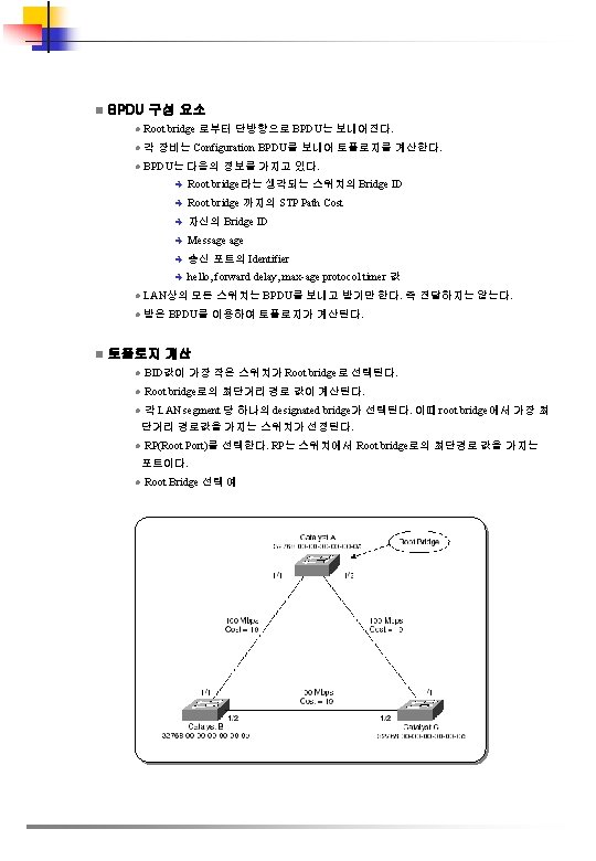
n Bridge ID l Loop 방지를 위한 Root Bridge 선택을 위하여 Bridge ID가 필요하다. l네트워크 상의 각 VLAN은 고유의 64 -bit bridge ID를 가지고 있다. l bridge priority 값과 extended system ID, STP MAC address 할당에 대한 정보를 가지고 있다. n Bridge Priority 값 l 12. 1. 8 a. E 이후 버전에서는 4 bit 값을 가진다. . l 그 전의 버전에서는 16 bit 값을 가지며 다음과 같다. Bridge Priority Value Bit 16 Bit 15 Bit 14 Bit 13 Bit 12 Bit 11 Bit 10 Bit 9 Bit 8 Bit 7 Bit 6 Bit 5 Bit 4 Bit 3 Bit 2 Bit 1 32768 16384 8192 4096 2048 1024 512 256 128 64 32 16 8 4 2 1 n Extended System ID l 12. 1. 8 a. E 이후 버전에서는 Bridge Priority 에 4 bit를 사용하고, 나머지 12 bit를 System ID 값으로 사용한다. l VLAN ID( 1 ~ 4094 ) 가 Extended system ID로 사용된다 Bridge Priority Value Extended System ID (Set Equal to the VLAN ID) Bit 16 Bit 15 Bit 14 Bit 13 Bit 12 Bit 11 Bit 10 Bit 9 Bit 8 Bit 7 Bit 6 Bit 5 Bit 4 Bit 3 Bit 2 Bit 1 32768 16384 8192 4096 2048 1024 512 256 128 64 32 16 8 4 2 1 n Mac Address l 64 bit 에서 Bridge Priority 와 Extended System ID 로 12 bit를 사용하고 나머지 48 bit는 MAC Address를 사용한다. l VLAN ID( 1 ~ 4094 ) 가 Extended system ID로 사용된다 n Bridge Protocol Data Unit l STP는 BPDU를 통해서 스위치간 정보를 교환한다. l Switch는 자신의 주변 Switch들을 모르기 때문에 자기 Port의 고유 MAC 어드레스를 Source로 STP multicast mac 어드레스인 01 -80 -C 2 -00 -00 -00 를 Destination으로 BPDU를 내보낸다. l BPDU의 종류 è Configuration BPDU : STP 계산 è Topology Change Notification(NCN) BPDU : Network Topology 의 변경을 보고 l BPDU를 통하여 Spanning Tree 토폴로지를 계산한다.
n Electing a Root Ports Root Bridge Port 에서 나가는 Cost 는 0 이다
n Electing Designated Ports l 기본적으로 Root Bridge의 모든 Port는 Designated Port 이다. l Root Port외 Designate Port 설정시는 Priority 값이 같다면 다음 Bridge ID값이 낮은 것을 Designated Port로 설정한다. 따라서 위의 예에서는 Switch B의 MAC이 낮 기 때문에 Switch B의 ½ Port가 Designated Port가 된다
2. 11. 3 STP 설정 n Default STP 설정 l Catalyst 6500에 설정되어있는 기본적인 Spanning Tree Protocol의 내용은 아래와 같다. l Default 상태로 설정되어 있을 경우에 Tie Breaker는 주로 Mac Address가 된다. Feature Default Value Enable state 모든 VLAN STP 활성화 Bridge priority 32768 STP port priority (configurable on a per-port basis—used on LAN ports configured as Layer 2 access ports) 128 STP port cost (configurable on a per-port basis—used on LAN ports configured as Layer 2 access ports) STP VLAN port priority (configurable on a per-VLAN basis—used on LAN ports configured as Layer 2 trunk ports) STP VLAN port cost (configurable on a per-VLAN basis—used on LAN ports configured as Layer 2 trunk ports) • 10 -Gigabit Ethernet: 2 • Gigabit Ethernet: 4 • Fast Ethernet: 19 • Ethernet: 100 128 • 10 -Gigabit Ethernet: 2 • Gigabit Ethernet: 4 • Fast Ethernet: 19 • Ethernet: 100 Hello time 2 초 Forward delay time 15 초 Maximum aging time 20 초 Mode PVST
n STP 활성화 l STP는 기본적으로 모든 VLAN에 활성화 되어 있다. l STP를 VLAN별로 선별적으로 활성화 할 수 있으며, 모든 VLAN에 STP를 비활성화 시킬 수도 있다. l 물리적으로 Loop 구조가 아닐 경우에는 인터페이스가 STP 로 인한 지연시간을 줄이 기 위하여 비활성화 시킬 수 있으나, 실수 등으로 Loop 구조를 만들었을 때는 큰 문제 를 야기할 수 있다. l 기본적으로 설정되어 있으므로 show running 명령어로 설정 상태를 보면, 나타나지 않는다. Command Purpose Router(config)# spanning-tree vlan_ID VLAN 단위로 STP를 활성화 이때 vlan_ID 값은 1 ~ 4094를 사용할 수 있다, (reserved VLAN 제외) Router(config)# default spanning-tree vlan_ID 모든 STP parameter를 기본 설정으로 원 복한다. Router(config)# no spanning-tree vlan_ID 특정 VLAN에 대하여 STP를 비활성화한 다. 기본 값이 변하는 만큼 물리적으로 Loop 구조가 아닌지 주의 필요 Step 2 Router(config)# end configuration mode를 나감 Step 3 Router# show spanning-tree vlan_ID VLAN에 대한 STP 상태 조회 Step 1 Router# configure terminal Router(config)# spanning-tree vlan 200 Router(config)# end Router# show spanning-tree vlan 200 VLAN 0200 Spanning tree enabled protocol ieee Root ID Priority 32768 Address 00 d 0. 00 b 8. 14 c 8 This bridge is the root Hello Time 2 sec Max Age 20 sec Forward Delay 15 sec Bridge ID Priority 32768 Address 00 d 0. 00 b 8. 14 c 8 Hello Time 2 sec Max Age 20 sec Forward Delay 15 sec Aging Time 300 Interface Role Sts Cost Prio. Nbr Status -------- -----------------Fa 4/4 Desg FWD 200000 128. 196 P 2 p Fa 4/5 Back BLK 200000 128. 197 P 2 p Router#
n Extended System ID 설정 l Catalyst 6500은 기본적으로 1024개의 VLAN 수를 지원한다. l 1 ~ 4094 개의 VLAN Number를 지원하기 위하여서는 Extended System ID를 설 정하 여야 한다. Command Purpose Router(config)# spanning-tree extend system-id extended system ID 활성화 VLAN을 1 ~ 4094 까지 사용할 수 있도록 증가 Router(config)# no spanning-tree extend system-id extended system ID 비활성화 Step 2 Router(config)# end configuration mode를 나감 Step 3 Router# show spanning-tree vlan_ID VLAN에 대한 STP 상태 조회 Step 1 Router# configure terminal Router(config)# spanning-tree extend system-id Router(config)# end Router# show spanning-tree summary | include Extended system ID is enabled. n Root Bridge 설정 l 가장 낮은 Bridge ID를 가지고 있는 스위치가 Root Bridge가 된다. l Root Bridge를 만드는 명령어는 spannig-tree vlan_ID root 이다. 이 명령어를 사용 하면 Extended System ID가 설정되어 있지 않을 경우 기본값 32768 이 8192로 변경된다. l 만약 다른 스위치가 8192보다 낮을 경우에는 예를 들어 8000으로 설정되어 있으면 1 작은 7999로 변경된다. l Extended Sytstem ID를 사용할 경우에는 24576으로 변경된다. l 만약 다른 스위치가 24576보다 낮을 경우에는 예를 들어 1000으로 설정되어 있으면 4096 만틈 작은 20480으로 변경된다. l 만약 차감한 값이 1보다 작은 값이 나오면 Root 명령어는 인식되지 않는다. l Diameter는 STP 토폴로지 내의 어떠한 두 대의 스위치 간의 최대 Hop 수이다. 이를 조정함으로써 STP Timer의 값을 조정할 수 있다. 기본적으로 7 이다.
Step 1 Step 2 Command Purpose Router(config)# spanning-tree vlan_ID root primary [diameter hops [hello-time seconds]] 해당 스위치를 root bridge로 지정 vlan_ID 값은 1 ~ 4094 사용 가능 Router(config)# no spanningtree vlan_ID root bridge 설정 삭제 Router(config)# end configuration mode를 나감 Router# configure terminal Router(config)# spanning-tree vlan 10 root primary diameter 4 Router(config)# end Router# n Secondary Root Bridge 설정 l 스위치의 Default Bridge Priority 값이 32768이며, secondary root로 설정을 하면 이 값이 변경된다. l Extended System ID가 설정이 안된 경우에는 16384 로 변경 l Extended System ID가 설정된 경우에는 28672가 된다. Step 1 Step 2 Command Purpose Router(config)# [no] spanningtree vlan_ID root secondary [diameter hops [hello-time seconds]] 해당 스위치를 secondary root bridge로 지정 vlan_ID 값은 1 ~ 4094 사용 가능 Router(config)# no spanningtree vlan_ID root bridge 설정 삭제 Router(config)# end configuration mode를 나감 Router# configure terminal Router(config)# spanning-tree vlan 10 root secondary diameter 4 Router(config)# end Router#
n STP Port Priority 설정 l 하나의 스위치의 두 개 이상의 포트가 Loop 가 형성되었을 경우 Tie Breaker의 역할을 하는 값으로서 기본은 128이다. l 0 ~ 240 까지 설정할 수 있으며, 16 단위로 증가 할 수 있다. Command Purpose Router(config)# interface {{type slot/port} | {port-channel port_channel_number}} 해당 인터페이스 선정 Router(config-if)# spanning-tree portpriority port_priority 해당 인터페이스의 port priority 설정 port_priority 값은 1부터 252 까지 설정할 수 있으며 4단위로 증가 Router(config-if)# no spanning-tree portpriority default port priority 값으로 원복 Router(config-if)# spanning-tree vlan_ID port-priority port_priority VLAN별로 port priority 설정 port_priority 값은 1부터 252 까지 설정할 수 있으며 4단위로 증가 Router(config-if)# [no] spanning-tree vlan_ID port-priority default VLAN port priority default port priority 값으로 원복 Step 4 Router(config-if)# end configuration mode를 나감 Step 5 Router# show spanning-tree interface {type slot/port} | {port-channel port_channel_number} Router# show spanning-tree vlan_ID 설정상태 조회 Step 1 Step 2 Step 3 Router# configure terminal Router(config)# interface fastethernet 4/4 Router(config-if)# spanning-tree port-priority 160 Router(config-if)# end Router# show spanning-tree interface fastethernet 4/4 Vlan Role Sts Cost Prio. Nbr Status -------- -------------------VLAN 0001 Back BLK 200000 160. 196 P 2 p VLAN 0006 Back BLK 200000 160. 196 P 2 p . . . VLAN 0198 Back BLK 200000 160. 196 P 2 p VLAN 0199 Back BLK 200000 160. 196 P 2 p VLAN 0200 Back BLK 200000 160. 196 P 2 p Router# l 만약 fastethernet 4/4 가 트렁크일 경우 VLAN별로 Priority를 설정 할 수 있다. Router# configure terminal Enter configuration commands, one per line. End with CNTL/Z. Router(config)# interface fast. Ethernet 4/4 Router(config-if)# spanning-tree vlan 200 port-priority 64 Router(config-if)# ^Z Router#
Router# show spanning-tree interface fastethernet 4/4 Vlan Role Sts Cost Prio. Nbr Status -------- ----------------VLAN 0001 Back BLK 200000 160. 196 P 2 p VLAN 0006 Back BLK 200000 160. 196 P 2 p . . . VLAN 0199 Back BLK 200000 160. 196 P 2 p VLAN 0200 Desg FWD 200000 64. 196 P 2 p Router# show spanning-tree vlan 200 interface fast. Ethernet 4/4 Interface Role Sts Cost Prio. Nbr Status -------- ----------------Fa 4/4 Desg LRN 200000 64. 196 P 2 p n STP Port Cost 설정 l 하나의 스위치의 두 개 이상의 포트가 Loop 가 형성되었을 경우 Tie Breaker의 역 할을 하는 값으로서 기본값은 인터페이스 속도에 따라 다른다. l 0 ~ 200000 까지 설정할 수 있으며, 어떠한 설정도 없을 경우에는 최종적인 Tie Breaker의 역할을 하는 것은 인터페이스 Number이며, 가장 작은 Number가 선 택된다. Command Purpose Router(config)# interface {{type slot/port} | {port-channel port_channel_number}} 해당 인터페이스 선정. Router(config-if)# spanning-tree cost port_cost 해당 인터페이스의 port_cost 값을 1 ~ 20000 까지 설정 Router(config-if)# no spanningtree cost 기본 인터페이스 cost 값으로 원복 Step 3 Router(config-if)# [no] spanningtree vlan_ID cost port_cost 해당 VLAN의 port_cost 값을 1 ~ 20000 까지 설정 Step 4 Router(config-if)# no spanningtree vlan_ID cost 기본 VLAN port cost 값으로 원복 Step 5 Router(config-if)# end configuration mode 나감 Step 6 Router# show spanning-tree interface {type slot/port} | {port-channel port_channel_number} show spanning-tree vlan_ID 설정 상태 조회 Step 1 Step 2 Router# configure terminal Enter configuration commands, one per line. End with CNTL/Z. Router(config)# interface fast. Ethernet 4/4 Router(config-if)# spanning-tree cost 1000 Router(config-if)# ^Z Router#
Router# show spanning-tree interface fast. Ethernet 4/4 Vlan Role Sts Cost Prio. Nbr Status -------- --------------VLAN 0001 Back BLK 1000 160. 196 P 2 p VLAN 0006 Back BLK 1000 160. 196 P 2 p VLAN 0007 Back BLK 1000 160. 196 P 2 p VLAN 0008 Back BLK 1000 160. 196 P 2 p VLAN 0009 Back BLK 1000 160. 196 P 2 p VLAN 0010 Back BLK 1000 160. 196 P 2 p Router l 만약 fastethernet 4/4 가 트렁크일 경우 VLAN별로 Cost를 설정 할 수 있다. Router# configure terminal Enter configuration commands, one per line. End with CNTL/Z. Router(config)# interface fast. Ethernet 4/4 Router(config-if)# spanning-tree vlan 200 cost 2000 Router(config-if)# ^Z Router# show spanning-tree vlan 200 interface fast. Ethernet 4/4 Interface Role Sts Cost Prio. Nbr Status -------- --------------Fa 4/4 Desg FWD 2000 64. 196 P 2 p n VLAN의 Bridge Priority 설정 l 이 설정을 할 경우는 조심하여야 하며, 대부분의 경우는 root primary 나 root secondary 명령어를 사용한다. Command Purpose Router(config)# spanning-tree vlan_ID priority bridge_priority VLAN bridge priority 값을 1 부터 65535 까지 설정 가능 Router(config)# no spanning-tree vlan_ID priority 기본 값으로 원복. Step 2 Router(config)# end configuration mode를 나감 Step 3 Router# show spanning-tree vlan_ID bridge [detail] 상태 조회 Step 1 l Extended System ID가 설정되어 있을 경우, 설정은 다음과 같다. Command Purpose Router(config)# [no] spanning-tree vlan_ID priority {0 | 4096 | 8192 | 12288 | 16384 | 20480 | 24576 | 28672 | 32768 | 36864 | 40960 | 45056 | 49152 | 53248 | 57344 | 61440} Extended sytem ID가 설정되어 있을 때 VLAN bridge priority 값 설정 4096 단위로 증가 Router(config)# no spanning-tree vlan_ID priority default bridge priority 값으로 원복 Step 2 Router(config)# end Configuration mode를 나감 Step 3 Router# show spanning-tree vlan_ID bridge [detail] 상태 조회 Step 1
Router# configure terminal Router(config)# spanning-tree vlan 200 priority 33792 Router(config)# end Router# show spanning-tree vlan 200 bridge Hello Max Fwd Vlan Bridge ID Time Age Delay Protoc ol -------------------- -----VLAN 200 33792 0050. 3 e 8 d. 64 c 8 2 20 15 ieee Router# n Hello Time 설정 l 이 설정을 할 경우는 조심하여야 하며, 대부분의 경우는 root primary 나 root secondary 명령어를 사용하여 조정하는 것이 바람직하다. Command Purpose Router(config)# spanning-tree vlan_ID hello-time hello_time VLAN에 대한 hello time 설정 hello_time 값의 범위는 1 ~ 10 초 vlan_ID 값의 범위는 1 ~ 4094 Router(config)# no spanningtree vlan_ID hello-time default hello time 값으로 원복 Step 2 Router(config)# end configuration mode를 나감 Step 3 Router# show spanning-tree vlan_ID bridge [detail] 상태 조회 Step 1 Router# configure terminal Router(config)# spanning-tree vlan 200 hello-time 7 Router(config)# end Router# show spanning-tree vlan 200 bridge Hello Max Fwd Vlan Bridge ID Time Age Delay Protocol -------------------- -------VLAN 200 49152 0050. 3 e 8 d. 64 c 8 7 20 15 ieee Router#
n Forward-Delay Time 설정 l 기본적으로 15초로 설정되어 있으며, 설정을 통하여 조정할 수 있다. Command Purpose Router(config)# spanningtree vlan_ID forwardtime forward_time VLAN에 대한 forward time 설정 hello_time 값의 범위는 4 ~ 30 초 vlan_ID 값의 범위는 1 ~ 4094 Router(config)# no spanning -tree vlan_ID forwardtime default forward time 값으로 원복 Step 2 Router(config)# end configuration mode를 나감 Step 3 Router# show spanning-tree vlan_ID bridge [detail] 상태 조회 Step 1 Router# configure terminal Router(config)# spanning-tree vlan 200 forward-time 21 Router(config)# end Router# show spanning-tree vlan 200 bridge Hello Max Fwd Vlan Bridge ID Time Age Delay Protocol -------------------- -------VLAN 200 49152 0050. 3 e 8 d. 64 c 8 2 20 21 ieee Router# n Maximum Aging Time 설정 l 기본적으로 20초로 설정되어 있으며, 설정을 통하여 조정할 수 있다. Command Purpose Router(config)# spanning-tree vlan_ID max-age max_age VLAN에 대한 maximum aging time 설정 hello_time 값의 범위는 6 ~ 40 초 vlan_ID 값의 범위는 1 ~ 4094 Router(config)# no spanningtree vlan_ID max-age default maximum aging time 값으로 원복 Step 2 Router(config)# end configuration mode를 나감 Step 3 Router# show spanning-tree vlan_ID bridge [detail] 상태 조회 Step 1 Router# configure terminal Router(config)# spanning-tree vlan 200 max-age 36 Router(config)# end Router# show spanning-tree vlan 200 bridge Hello Max Fwd Vlan Bridge ID Time Age Delay Protocol -------------------- -------VLAN 200 49152 0050. 3 e 8 d. 64 c 8 2 36 15 ieee Router#
n BPDU Filtering l Spanning Tree를 동작하지 않으며, 불필요한 BPDU 정보를 받거나 보내는 것을 원치 않을 경우 BPDU Filtering을 할 수 있다. Command Purpose Step 1 Router(config)# interface fast. Ethernet 4/4 해당인터페이스 선정 Step 2 Router(config-if)# spanningtree bpdufilter enable BPDU filtering 활성화 Step 3 Router# show spanning-tree interface fast. Ethernet 4/4 상태 조회 Router(config)# interface fast. Ethernet 4/4 Router(config-if)# spanning-tree bpdufilter enable Router(config-if)# ^Z Router# show spanning-tree interface fast. Ethernet 4/4 Vlan Role Sts Cost Prio. Nbr Status -------- ------------------VLAN 0010 Desg FWD 1000 160. 196 Edge P 2 p Router# show spanning-tree interface fast. Ethernet 4/4 detail Port 196 (Fast. Ethernet 4/4) of VLAN 0010 is forwarding Port path cost 1000, Port priority 160, Port Identifier 160. 196. Designated root has priority 32768, address 00 d 0. 00 b 8. 140 a Designated bridge has priority 32768, address 00 d 0. 00 b 8. 140 a Designated port id is 160. 196, designated path cost 0 Timers: message 0, forward delay 0, hold 0 Number of transitions to forwarding state: 1 The port is in the portfast mode by portfast trunk configuration Link type is point-to-point by default Bpdu filter is enabled BPDU: sent 0, received 0 Router#
n Default Hardware 3 스위칭 설정 하드웨어 레이어 3 스위칭 enable 상태 enable(disable 될 수 없음) MFSC 2에서 시스코 IOS CEF enable 상태 enable(disable 될 수 없음) MFSC 2에서 시스코 IOS d. CEF enable 상태 enable(disable 될 수 없음) IGMP 스누핑 enable MSFC 2에서 멀티캐스트 disable MFSC 2에서 PIM 라우팅 disable IP 멀티캐스트 레이어 3 스위칭 멀티캐스트 라우팅 또는 IP PIM이 enable되면 eable n n RPR Trigger 조건 Layer 3 Switching 설정 가이드 및 제한 l PFC 2 최대 16개의 HSRP 그룹멤버를 지원한다. l Hardware Layer 3 switching은 아래의 입출력 encapsulation을 지원한다. Ethernet V 2. 0(ARPA) 802. 3 with 802. 2 with 1 byte control(SAP 1) 802. 3 with 802. 2 and SNAP Hardware Layer 3 Switching 설정 PFC 2, MSFC 2 및 DFC가 있는 Supervisor Engine 2의 Hardware Layer 3 switching 은 자동으로 활성화되며 추가의 설정이 필요하지 아니하다. Layer 3 스위칭 된 트래픽의 정보를 보기 위하여 아래의 작업을 수행한다 l 하드웨어 레이어 3 스위칭 설정 Command Purpose Router# show interface {{type 1 slot/port} | {port-channel number}} | begin L 3 레이어 3 스위칭된 트래픽 합계를 디스플레이 함 Type=ethernet, fastethernet, gigabitethernet, tengigabitethernet Router# show interface fastethernet 3/3 | begin L 3 in Switched: ucast: 0 pkt, 0 bytes - mcast: 12 pkt, 778 bytes mcast L 3 out Switched: ucast: 0 pkt, 0 bytes - mcast: 0 pkt, 0 bytes 4046399 packets input, 349370039 bytes, 0 no buffer Received 3795255 broadcasts, 2 runts, 0 giants, 0 throttles <…이하 생략. . . > Router#
시스코 IOS CEF와 d. CEF는 MSFC 2에서 영구적으로 enable 된다. 하드웨어 레이어 3 스위칭을 지 원을 위하여 어떠한 설정도 필요하지 아니하다. l 하드웨어 레이어 3 스위칭 통계 보기 하드웨어 레이어 3 스위칭 통계는 VLAN 별로 볼 수 있다. Command Purpose Router# show interfaces {{type 1 slot/port} | {port-channel number}} 하드웨어 레이어 3 통계 보기. Router# show interfaces gigabitethernet 9/5 | include Switched L 2 Switched: ucast: 8199 pkt, 1362060 bytes - mcast: 6980 pkt, 371952 bytes L 3 in Switched: ucast: 0 pkt, 0 bytes - mcast: 0 pkt, 0 bytes mcast L 3 out Switched: ucast: 0 pkt, 0 bytes - mcast: 0 pkt, 0 bytes l adjacency 테이블 정보 보기 Command Purpose Router# show adjacency [{{type 1 slot/port} | {port-channel number}} | detail | internal | summary] adjacency 테이블 정보 보기 detail옵션은 상세내용 보기 Router# show adjacency gigabitethernet 9/5 detail Protocol Interface Address IP Gigabit. Ethernet 9/5 172. 20. 53. 206(11) 504 packets, 6110 bytes 00605 C 865 B 82 000164 F 83 FA 50800 ARP 03: 49: 31
2. 13 Network Security 설정 n ACL 설정 가이드 Access 그룹에 의하여 패킷이 드롭되면 MFSC는 default로 ICMP unreachable 메시지 를 보낸다. ACL에 의하여 drop되는 패킷에 대한 ICMP 메시지의 처리를 위한 CPU의 부하부담을 줄이고 싶다면 no ip unreachable명령어와 no ip redirects를 인터페이스에 설정하라 n VLAN ACL 개요 VACL은 하드웨어로 처리며, IPX 및 MAC-Layer 트래픽에 대해서도 적용할 수 있다. n Bridged Packet 아래의 그림은 bridged packet이 적용된 VACL을 보여준다. n Routed Packet Routed 또는 Layer 3 -switched Packet은 아래와 같은 순서에 의하여 수행된다. l VACL for input ACL l Output Cisco IOS ACL l VACL for output VLAN
l 매칭 절의 설정 Command Purpose Router(config-access-map)# match {ip address {1 -199 | 1300 -2699 | acl_name} | ipx address {800 -999 | acl_name}| mac address acl_name} 매칭절을 만듬 Router(config-access-map)# no match {ip address {1 -199 | 1300 -2699 | acl_name} | ipx address {800 -999 | acl_name}| mac address acl_name} 매칭절 지움 l하나 또는 복수개의 ACL을 선택할 수 있다. l. WAN l. No 인터페이스에 부착된 VACL은 표준 및 확장 IP ACL만 지원한다. 키워드를 사용하여 ACL을 지울 수 있다. l 실행 절의 설정 Command Purpose Router(config-access-map)# action {drop [log]} | {forward [capture]} | {redirect {{ethernet | fastethernet | gigabitethernet | tengigabitethernet} slot/port} | {port-channel_id}} VLAN 엑세스 맵에서 실행절 설정 Router(config-access-map)# no action {drop [log]} | {forward [capture]} | {redirect {{ethernet | fastethernet | gigabitethernet | tengigabitethernet} slot/port} | {port-channel_id}} 실행절 삭제 l패킷을 드롭, 포워드, 리다이렉트 시킬 수 있다. l. WAN l. Log 옵션은 수퍼바이져 엔진2에서만 지원된다. l. WAN l. Log 인터페이스에 부착된 VACL은 표준 및 확장 IP ACL만 지원한다. 인터페이스에 적용된 VACL은 log옵션을 지원하지 않는다. 옵션이 적용되면 단지 드롭 패킷만 log되어진다. l. Redirect옵션은 최대 5개 인터페이스까지 지정할 수 있다.
l VLAN 엑세스 맵에 적용 Command Purpose Router(config)# vlan filter map_name {vlan-list vlan_list | interface type number} CP_Cmd. Plain VLAN 또는 WAN 인터페이스 에 VLAN 엑세스 맵 적용 Router(config)# no vlan filter map_name [vlan-list vlan_list | interface type number ] VLAN 맵 삭제 l VLAN 엑세스 맵을 복수개의 VLAN 또는 WAN 인터페이스에 적용할 수 있다. l vlan_list 파라미터는 VLAN-ID 1개 또는 여러 개의 경우는 ‘, ’로 분리한다. l VACL이 적용된 WAN 인터페이스가 제거되면 VACL 설정도 제거된다. l 세컨더리 사설 VLAN에 VACL을 적용할 수 없다. l NO 키워드는 WAN 인터페이스 또는 VLAN에서 부터 VLAN 엑세스 맵을 지운다. l VLAN 엑세스 맵에 설정 Command Purpose Router# show vlan access-map [map_name] VLAN 엑세스 맵의 확인 Router# show vlan filter [access-map map_name | vlan_id | interface type 1 number 2 ] VACL 과 VLAN 간의 매핑 관계 확인 Router# show ip access-lists net_10 Extended IP access list net_10 permit ip 10. 0 0. 255 any Router# show ip access-lists any_host Standard IP access list any_host permit any
l VLAN 엑세스 맵 설정 및 확인 아래 예는 IP 패킷을 포워딩하기 위하여 VLAN 엑세스 맵을 정의하고 적용하는 방법이다. IP 트래픽 이 Net_10과 매칭되면 포워딩 되고, 아니면 드롭된다. Router(config)# vlan access-map thor 10 Router(config-access-map)# match ip address net_10 Router(config-access-map)# action forward Router(config-access-map)# exit Router(config)# vlan filter thor vlan-list 12 -16 아래의 예는 패킷을 드롭하고 로그를 남기기 위하여 VLAN 엑세스 맵을 적용하는 방법이다. 이 예에 서 IP 트레픽이 net_10과 매칭되면 드롭되고 로그가 납는다. 다른 패킷에 대하여는 포워딩 된다. Router(config)# vlan access-map ganymede 10 Router(config-access-map)# match ip address net_10 Router(config-access-map)# action drop log Router(config-access-map)# exit Router(config)# vlan access-map ganymede 20 Router(config-access-map)# match ip address any_host Router(config-access-map)# action forward Router(config-access-map)# exit Router(config)# vlan filter ganymede vlan-list 7 -9 아래 예는 IP 패킷을 포워딩하고 캡쳐하기 위한 VLAN 엑세스 맵을 정의하고 적용하는 방법이다. IP 트래픽이 net_10과 매칭되면 포워딩되고 캡쳐된다. 아니면 드롭된다. Router(config)# vlan access-map mordred 10 Router(config-access-map)# match ip address net_10 Router(config-access-map)# action forward capture Router(config-access-map)# exit Router(config)# vlan filter mordred vlan-list 2, 4 -6
l VACL 로그 설정 VACL로그는 아래와 같은 제한이 따른다. l수퍼바이져 엔진2에서만 지원된다. l리다이렉트 패킷을 위하여 rate-limit 기능 때문에 VACL 개수가 부정확할 수 있 다. l거부된 패킷만 로그된다. Command Purpose Step 1 Router(config)# vlan access-log maxflow max_number 로그 테이블 크기 설정. Step 2 Router(config)# vlan access-log ratelimit pps 최대 리다이렉트 VACL. 로그 패킷 rate Step 3 Router(config)# vlan access-log threshold pkt_count 로그 threshold 설정 Step 4 Router(config)# exit VLAN 엑세스 맵 빠져 나옴 Step 5 Router# show vlan access-log config (Optional) VACL 로그 property 봄 Step 6 Router# show vlan access-log flow protocol {{src_addr src_mask} | any | {hostname | host_ip}}} {{dst_addr dst_mask} | any | {hostname | host_ip}}} [vlan_id] (Optional) VACL 로그 테이블 내용 봄 Step 7 Router# show vlan access-log statistics (Optional) 패킷 및 메시지 카운터 정보 및 통계정보 확인 Router(config)# vlan access-log maxflow 800 Router(config)# vlan access-log ratelimit 2200 Router(config)# vlan access-log threshold 4000
l LCD 메시지 설정 Command Purpose Router(config)# fabric lcd-banner d message d LCD 메시지 디스플레이 설정 Router(config)# no fabric lcd-banner LCD 메시지 디스플레이 해제. l 모듈정보 보기 Command Purpose Router# show module {5 | 6 | 7 | 8} 모듈정보 보기. Router# show module 5 Mod Ports Card Type Model Serial No. ------------------- ------ 5 0 Switching Fabric Module WS-C 6500 -SFM SAD 04420 JR 5 Mod MAC addresses Hw Fw Sw Status ------------------- ------- 5 0001. 0002. 0003 to 0001. 0002. 0003 1. 0 6. 1(3) 6. 2(0. 97) Ok l SFM 모듈 리던던시 상태 Command Purpose Router# show fabric active SFM 모듈 리던던시 상태 Router# show fabric active Active fabric card in slot 5 No backup fabric card in the system Router#
l 패브릭 상태 보기 Command Purpose Router# show fabric status [slot_number | all] 패브릭 상태 보기 Router# show fabric status all slot channel module fabric status status 1 0 OK OK 3 1 OK 4 0 OK Router# l 패브릭 사용률 보기 Command Purpose Router# show fabric utilization [slot_number | all] 패브릭 사용률 확인 Router# show fabric utilization all slot channel Ingress % Egress % 1 0 0 0 3 1 0 4 0 0 4 1 0 6 0 0 6 1 0 7 0 0 7 1 0 Router#
l 패브릭 에러 보기 Command Purpose Router# show fabric errors [slot_number | all] 패브릭 에러 보기 Router# show fabric errors slot channel module fabric crc hbeat sync 1 0 0 0 3 1 0 0 0 4 0 0 0 4 1 0 0 0 6 0 0 0 6 1 0 0 0 7 0 0 0 7 1 0 0 0 Router#
2. 15 파워 및 환경 모니터링 n Power Redundancy 글로벌 설정모드에서 power redundancy-mode combined | redundant 명령어로 활 성화 및 비활성화 시킬 수 있으며, (디폴트로 활성화 되어 있음) 언제든지 변경 시킬 수 있다. n Power 모듈 ON/Off no power enable module slot 명령어로 모듈을 power down시킬 수 있다. power enable module slot 명령어로 모듈을 power on 시킬 수 있다. n 시스템 파워 상태 show power 명령어로 현재 시스템의 파워 상태를 볼 수 있다. Router# show power system power redundancy mode = redundant system power total = 1153. 32 Watts (27. 46 Amps @ 42 V) system power used = 397. 74 Watts ( 9. 47 Amps @ 42 V) system power available = 755. 58 Watts (17. 99 Amps @ 42 V) Power-Capacity PS-Fan Output Oper PS Type Watts A @42 V Status State ----------- ------1 WS-CAC-2500 W 1153. 32 27. 46 OK OK on 2 none Pwr-Requested Pwr-Allocated Admin Oper Slot Card-Type Watts A @42 V State ----------- ------ ----1 WS-X 6 K-SUP 2 -2 GE 142. 38 3. 39 on on 2 - - 142. 38 3. 39 - 5 WS-X 6248 -RJ-45 112. 98 2. 69 on on Router# n 시스템 환경 상태 모니터링 Show environment[alarm|status|temperature] 명령어는 시스템 상태를 보여준다. n LED 환경 상태 LED는 major와 minor 알람 타입이 있다.
n 슈퍼바이져와 스위칭 모듈를 통한 환경 감시 Component Supervisor 엔진 온도센서 major 기준치 1 초과 Alarm Type LED Indication Major STATUS LED red Action Syslog 메세지 and SNMP trap 발생 만약 리던던시가 있으면 Active supervisor엔 진은 shutdown이 되고 리던던시 슈버바이저가 그 역할을 수행 만약 리던던시가 없으면 Active supervisor엔 진은 5분 후에 정상적인 온도가 아니면 shutdown Supervisor 엔진 온도센서minor 기준치 초과 Minor STATUS LED orange Syslog 메세지 and SNMP trap 발생 상태 감시 Redundant supervisor engine 온 도센서 major 나 minor 기준치 초과 Major STATUS LED red 만약 major 경고 상태에서 5분 후에 정상적인 온도가 아니면 shutdown Minor STATUS LED orange 스위칭센스 온도센서 major 기준 치 초과 Major Syslog 메세지 and SNMP trap 발생 STATUS LED red 만약 minor 경고이면 상태 감시. Syslog 메세지 and SNMP trap 발생 모듈4 전원 차단 스위칭센스 온도센서 minor 기준 치 초과 Minor STATUS LED orange Syslog 메세지 and SNMP trap 발생. 상태 감시 * 만약 리던던시 슈퍼바이저가 없으면 System LED 가 LED 상태