CASNUB BOGIE CAST STEEL FRICTION SNUBBER BOGIE 1972

CASNUB BOGIE CAST STEEL FRICTION SNUBBER BOGIE 1972 -FITTED ON BOI (TESTED UPTO 110 KMPH) 1981 -FITTED IN BOX – N (TESTED UPTO 90 KMPH)
 3. CASNUB-22 W(M)")
CASNUB Contd… VARIOUS BOGIE VERSIONS 1. CASNUB-22 W 2. CASNUB-22 W(Retrofitted) 3. CASNUB-22 W(M) 4. CASNUB-22 NL 5. CASNUB-22 NLB 6. CASNUB-22 HS( AT 100 Kmph)


CASNUB Contd… Two cast side frames and a floating bolster • Bolster supported on side frames through two groups of springs which also incorporate load proportional friction damping. Side frames connected by fabricated mild steel spring plank • Fitted in BOXN, BCNA, BRN, BTPGLN Wagons. Max. Population on BOX N Wagons • Hunting at 90 kmph
 The bogie suspension")
CASNUB Contd… • CASNUB BOGIE/BOX ‘N’ WAGON • SUSPESION CHARACTERISTCS 1) The bogie suspension is at the bolster level only. If consists of two cast steel side frames, connected by riveted mild steel spring planks. 2) As there is no primary suspension system, the spring plank is subjected to bending and torsion during the wheels trying to adjust, for negotiating track twist
 The cast steel-floating bolster is supported on the side frame through")
CASNUB Contd… 3) The cast steel-floating bolster is supported on the side frame through two nests of springs. 4) The springs contain friction snubber for oscillation control. However these snubber springs are not designed to take vertical load of the wagon 5) The positive features of these bogies are lightweight, shorter overall length, ease of maintenance, high reliability and higher capacity of payload of 22. 9 t axle load
 The salient features of this bogies are – Wheel Diameter: 1000")
CASNUB Contd… 6) The salient features of this bogies are – Wheel Diameter: 1000 mm (new), 925 mm (condemning) Wheel base: 2000 mm Type of pivot: IRS spherical Type of roller bearing: Standard AAR tapered cartridge bearing Anti rotation features: Anti rotation lugs have been provided between bogie bolster and side-frame
 CASNUB 22 -W (M) is an improvised version of model CASNUB")
CASNUB Contd… 7) CASNUB 22 -W (M) is an improvised version of model CASNUB 22 -W. In these version elastomeric pads at the side bearer level and at the axle box level have been provided, this reduces hunting proneness of the bogie and biased wear of the wheel flanges. 8) The bogie is fitted with two groups of helical spring nests. The number of springs in a group can vary for various axle load is as under:

CASNUB Contd… Axle load No. of springs Outer Inner Snubber 22. 9 t: 14 10 4 20. 3 t: 12 8 16. 3 t: 8 8 4
Each bogie is provided with four friction snubbers for the purpose of")
CASNUB Contd… 10)Each bogie is provided with four friction snubbers for the purpose of damping of the oscillations. These snubbers are in the form of triangular cast steel, which is supported at the snubber springs. The springs should be replaced if minimum spring height is at or less than shown below:

 Snubbing arrangement & snubber Springs are same for 22. 9")
CASNUB Contd… NOTE: 1) Snubbing arrangement & snubber Springs are same for 22. 9 t, 20. 3 t & 16. 21 Axle Load 2) Details of the springs are as per Drg, No. WD-83069 -S/1 AXLE LOAD No. of springs required Outer Inner Snubber 22. 9 t 7 3 2 20. 3 t 6 4 2 16. 2 t 4 4 2 DETAIL OF SNUBBING, SRING GROUP ARRANGEMENT CASNUB BOGIES (EXCEPT CASNUB-22 HS BOGIE

NESTED SPRINGS FRICTION SNUBBER SPRING
 Recommended condemning free height (mm) Outer load")
CASNUB Contd… Spring Free height nominal (mm) Recommended condemning free height (mm) Outer load spring 260 245 Inner load spring 262 247 Snubber spring 294 279 Matching of both load and snubber spring is important. The springs should not have free height variation more than 3 mm, assembled in the same group.

CASNUB Contd. . Fig. No. 3. 69

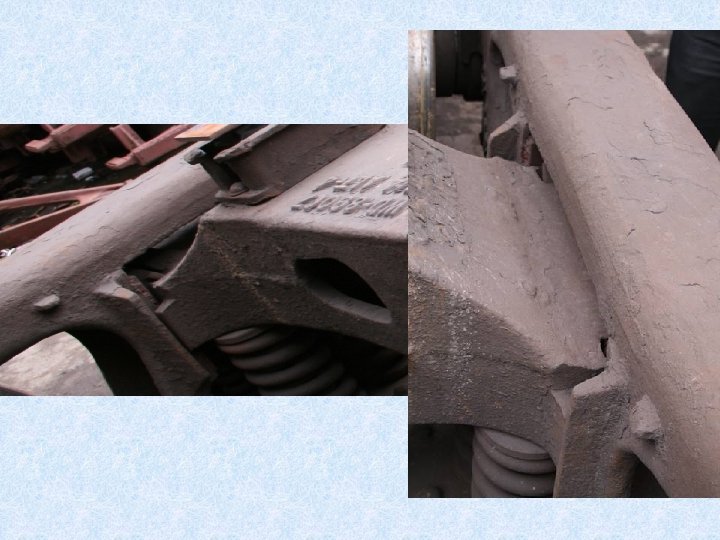
FRICTION SNUBBER WEARING SURFACES
 Body weight is transferred to the bogie through IRS spherical")
CASNUB Contd. . 11) Body weight is transferred to the bogie through IRS spherical centre pivot. Centre pivot is to be lubricated with graphite grease. 12) CASNUB 22 -W bogie is provide with a roller type side bearer, it has now been modified to constant contact metal bonded rubber pad 13) The main clearance of bogie assembly is placed as under.

CASNUB Contd…


UNEQUAL WEAR

CASNUB Contd. . Fig. No. 3. 70


CASNUB contd. .

CASNUB contd… 1. Side Frame Column Sides 2. Anti – Rotation lugs 3. Side frame friction liners 4. Pedestal Crown Roof 5. Pedestal Crown Sides & Pedestal Sides 6. Pedestal Jaws LOCATIONS OF WORN SIDE FRAME –Fig. No. 3. 73
 Clearances of Bogie Assembly (Fig. 8. 23) Cylindric al roller bearing")
CASNUB Contd… 14) Clearances of Bogie Assembly (Fig. 8. 23) Cylindric al roller bearing axle box (1) Lateral clearance between 18 mm side frame and bolster (2) Lateral clearance between 25 mm side frame and axle box adapter (3) Longitudinal clearance 2 mm between side frame and axle box adapter Cartridge type unit adapter 18 mm 25 mm 2 mm
 (4) Longitudinal clearance between side")
CASNUB Contd… Clearances of Bogie Assembly (Fig. 8. 23) (4) Longitudinal clearance between side frame and bolster (5) Lateral clearance between side frame and axle box crown (6) Clearance between Antirotation lug and bolster Cylindric al roller bearing axle box 6 mm Cartridge type unit adapter 7 mm 4 mm 6 mm
 CASNUB bogie assembly consists of side frames, spring plank, bolster, friction")
CASNUB Contd… 15) CASNUB bogie assembly consists of side frames, spring plank, bolster, friction shoes, load bearing spring, snubber spring, centre pivot, wheel set with roller bearings.

CASNUB Contd… SPECIAL BOGIE FREIGHT STOCK 1. Bolster – Wearing surface of the bolster are shown in fig. 3. 70. The limits of wear are as under: Item a) Bolster Pocket 35±° slope surface (liner) New Worn (mm) out (mm) 8 3 Wear Fig Condemning limit No Procedure Using Gauges (mm) 5 -The 8 mm thick manganese steel liner welded with pocket slope can be permitted in service upto a thickness of 3 mm
 b) 444 Bolster land surface Worn")
CASNUB Contd… 1. Bolster –Contd… Item New (mm) b) 444 Bolster land surface Worn out (mm) 438 Wear limit (mm) 3 mm on either side Fig No Condemning Procedure Using Gauges 3. 71 With gauge placed centrally I. e. its central line matching with that of the casting (bolster), a 4 mm shim should not get inserted between the gauge and Land Surfaces or Rotation.
")
CASNUB Contd… 1. Bolster –Contd… Item New Worn Wear Fig out limit No c) Rotation Stop 518 512 3 Condemning Procedure Using Gauges 3. 71 Stop Lugs on the Bolster with two shims used simultaneously on both surfaces
 Worn Wear Fig out limit No")
CASNUB Contd… 1. Bolster –Contd… Item New (mm) Worn Wear Fig out limit No (mm) d) Bolster Column Gibs Outer gib 234 244 5 Inner gib 136 144 5 Condemning Procedure Using Gauges With gauge in position, if a 6 mm shim could be inserted between gauge and Outer / 3. 72 Inner gib, condemning limit is reached
 Centre Pivot New Worn Wear Fig limit")
CASNUB Contd… 1. Bolster –Contd… Item e) Centre Pivot New Worn Wear Fig limit No (mm) out (mm) --- Vertical side -- -- 5. 5 3. 68 Seat -- -- 4 -- Condemning Procedure Using Gauges To be used for integral / separate type CP bottom bolsters. Placing gauge in position, if surfaces marked on gauge starts touching the bolster surface at any point or a 6 mm shim can be inserted between Vertical wall of CP and gauge, it has reached its condemning

CASNUB Contd… 2. SIDE FRAME – The wearing surfaces of the side frame are shown I fig. 3. 73 – The lmits of wear are as under: Item New (mm) Worn Wear out limit (mm) Fig No Condemning Procedure Using Gauges a. Side frame column Friction Plate 10 6 -- The 10 mm thick Manganese steel liner welded with column may be permitted in service up to a thickness of 6 mm. 4
- Slides: 38