
Case study on directing plastic hinges from columns


- Slides: 29
Case study on directing plastic hinges from columns into beams Scientific Team: asist. dr. ing. Ioana Olteanu prof. dr. ing. Alex Barbat (from UPC, Barcelona, Spain) ing. Radu Canarache Bucuresti, Mai 2013
CONTENT: Natural disasters Vulnerability Seismic risk assessment Case studies
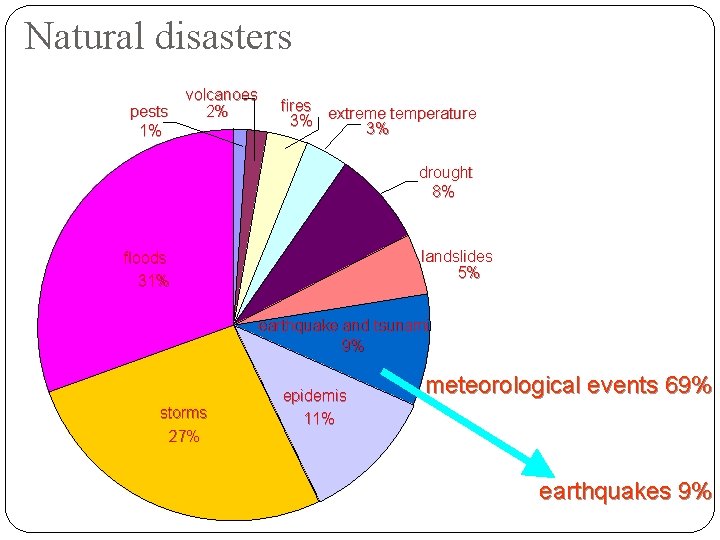
Natural disasters pests 1% volcanoes 2% fires extreme temperature 3% 3% drought 8% landslides 5% floods 31% earthquake and tsunami 9% storms 27% epidemis 11% meteorological events 69% earthquakes 9%
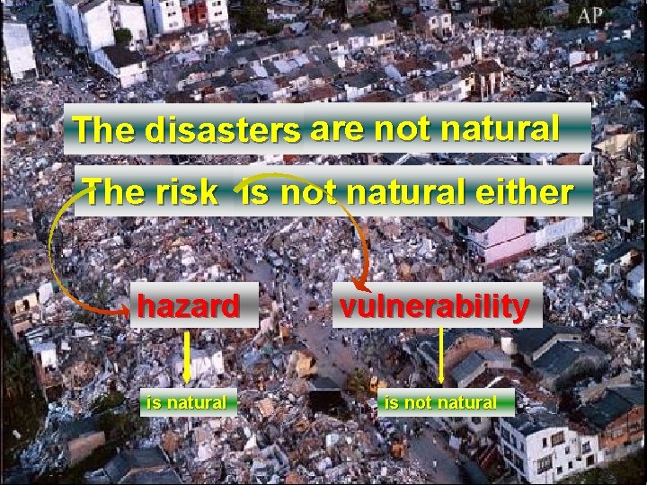
The disasters are not natural The risk is not natural either hazard is natural vulnerability is not natural
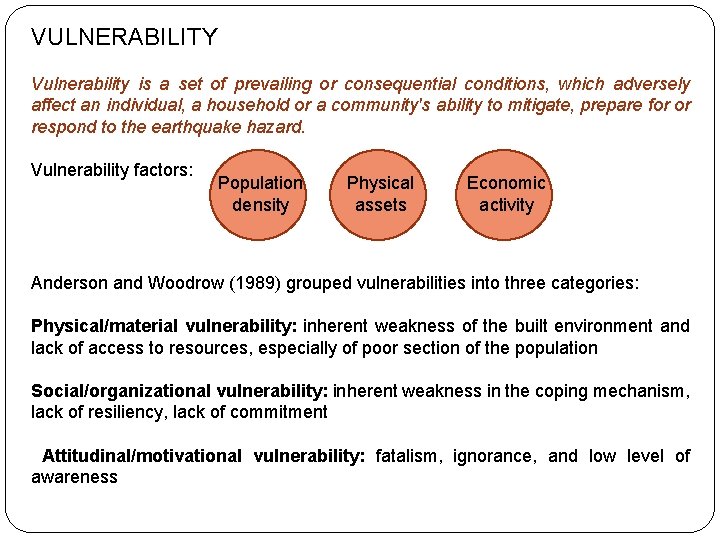
VULNERABILITY Vulnerability is a set of prevailing or consequential conditions, which adversely affect an individual, a household or a community's ability to mitigate, prepare for or respond to the earthquake hazard. Vulnerability factors: Population density Physical assets Economic activity Anderson and Woodrow (1989) grouped vulnerabilities into three categories: Physical/material vulnerability: inherent weakness of the built environment and lack of access to resources, especially of poor section of the population Social/organizational vulnerability: inherent weakness in the coping mechanism, lack of resiliency, lack of commitment Attitudinal/motivational vulnerability: fatalism, ignorance, and low level of awareness
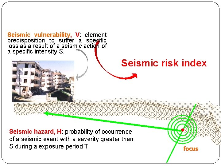
Seismic vulnerability, V: element predisposition to suffer a specific loss as a result of a seismic action of a specific intensity S. Seismic risk index Seismic hazard, H: probability of occurrence of a seismic event with a severity greater than S during a exposure period T. focus
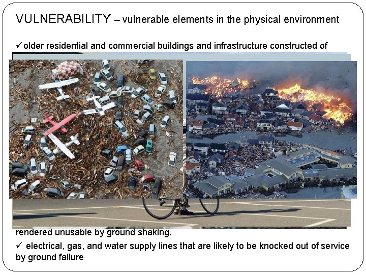
VULNERABILITY – vulnerable elements in the physical environment üolder residential and commercial buildings and infrastructure constructed of unreinforced masonry (i. e. , URM's) or construction materials with inadequate resistance to lateral forces; ü older non-engineered residential and commercial buildings that have no lateral resistance and are vulnerable to fire following an earthquake; ü new buildings and infrastructure that have not been sited, designed, and constructed with adequate enforcement; ü buildings and lifeline systems sited in close proximity to an active fault system, or on poor soils that either enhance ground shaking or fail through permanent displacements (e. g. , liquefaction and landslides), or in low-lying or coastal areas subject to either seiches or tsunami flood waves. ü schools and other buildings that have been built to low construction standards. ü communication and control centers that are concentrated in one area. ü hospital facilities that is insufficient for large number of casualties and injuries. ü bridges, overhead crossings and viaducts that are likely to collapse or be rendered unusable by ground shaking. ü electrical, gas, and water supply lines that are likely to be knocked out of service by ground failure
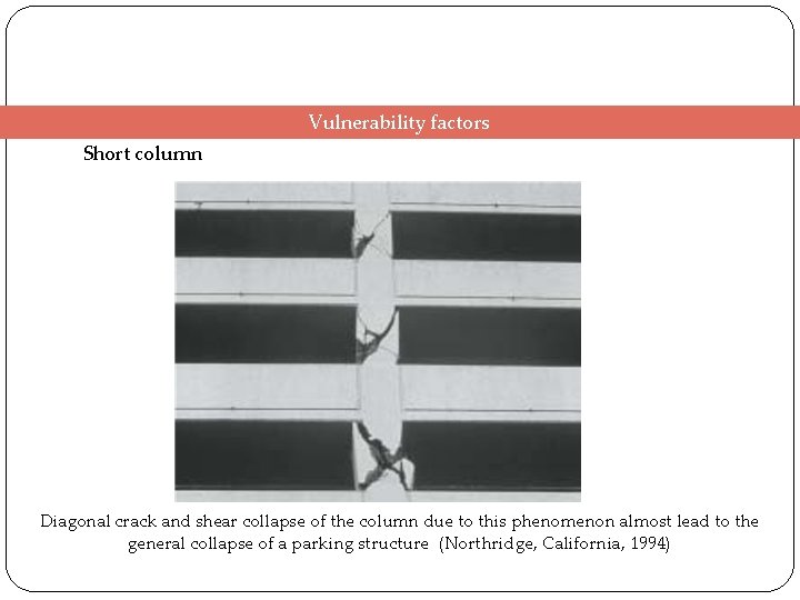
Vulnerability factors Short column Diagonal crack and shear collapse of the column due to this phenomenon almost lead to the general collapse of a parking structure (Northridge, California, 1994)
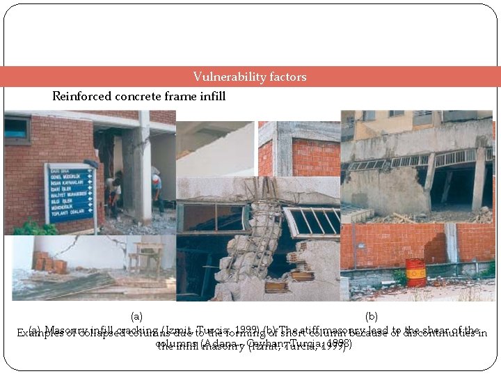
Vulnerability factors Reinforced concrete frame infill (a) (b) (a) Masonry infill cracking (Izmit, Turcia, 1999) (b) stiff masonry lead of to discontinuities the shear of thein Examples of collapsed columns due to the forming of The short column because columns - Ceyhan, Turcia, 1999) 1998) the infill (Adana masonry (Izmit, Turcia,
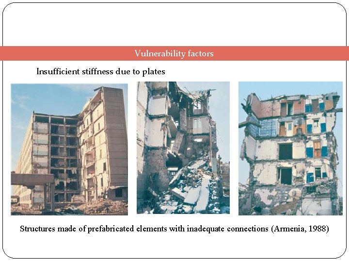
Vulnerability factors Insufficient stiffness due to plates Structures made of prefabricated elements with inadequate connections (Armenia, 1988)
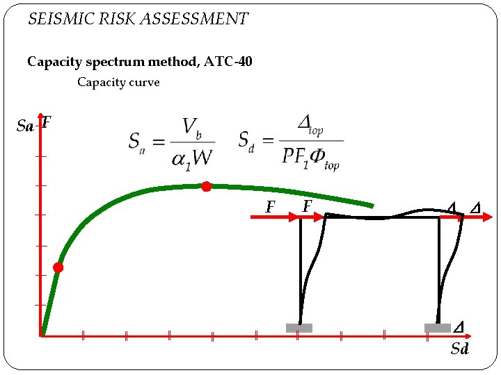
SEISMIC RISK ASSESSMENT Capacity spectrum method, ATC-40 Capacity curve Sa F F F Sd
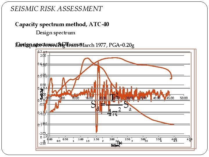
SEISMIC RISK ASSESSMENT Capacity spectrum method, ATC-40 Design spectrum, AD Sa-Tfrom format Earthquake recording March 1977, PGA=0. 20 g 0. 7 2. 00 0. 6 1. 50 1. 00 0. 5 Sa(0. 2 g) 0. 50 0. 4 0. 00 0. 3 -0. 50 5. 00 10. 00 15. 00 20. 00 25. 00 30. 00 35. 00 40. 00 45. 00 50. 00 0. 2 -1. 00 0. 1 -1. 50 0. 1 -2. 00 0 0 0. 00 0 -2. 50 0. 50 1 1. 00 1. 50 2 2. 00 2. 5 T(s) Sd(cm) 2. 50 3 3. 00 3. 50 4 4. 00 4. 50 5
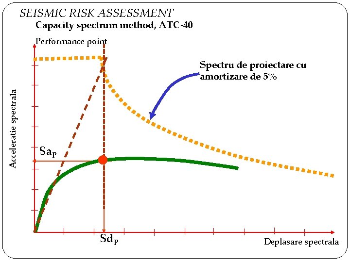
SEISMIC RISK ASSESSMENT Capacity spectrum method, ATC-40 Performance point Acceleratie spectrala Spectru de proiectare cu amortizare de 5% Sa. P Sd. P Deplasare spectrala
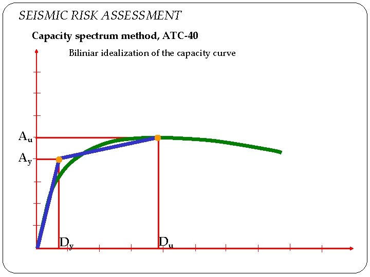
SEISMIC RISK ASSESSMENT Capacity spectrum method, ATC-40 Biliniar idealization of the capacity curve Au Ay Dy Du
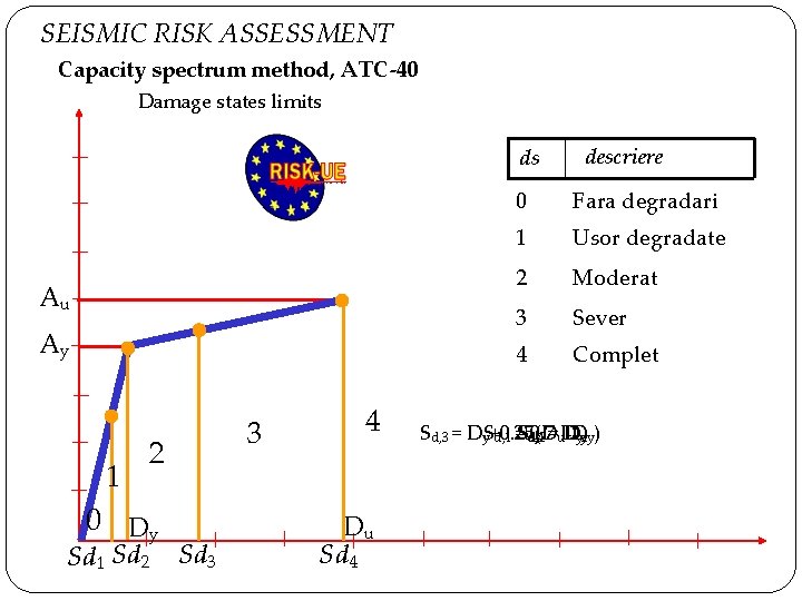
SEISMIC RISK ASSESSMENT Capacity spectrum method, ATC-40 Damage states limits ds Au Ay 1 3 2 0 Dy Sd 1 Sd 2 Sd 3 4 Du Sd 4 descriere 0 Fara degradari 1 Usor degradate 2 Moderat 3 Sever 4 Complet Sd, 3 = Dy. S+0. 25(D Sd, 4 0. 7=u. D D -D d, 1 = d, 2 yu y y)
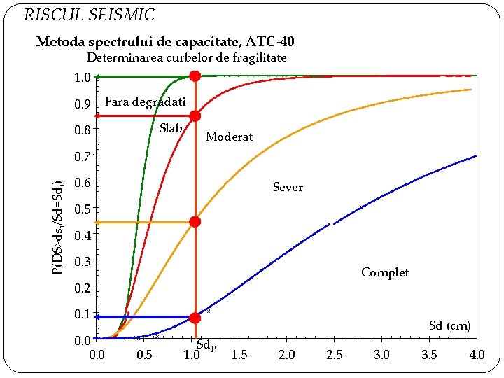
RISCUL SEISMIC Metoda spectrului de capacitate, ATC-40 Determinarea curbelor de fragilitate 1. 0 0. 9 Fara degradati 0. 8 Slab Moderat P(DS>dsi/Sd=Sdi) 0. 7 0. 6 Sever 0. 5 0. 4 0. 3 Complet 0. 2 0. 1 0. 0 Sd (cm) 0. 5 Sd. P 1. 0 1. 5 2. 0 2. 5 3. 0 3. 5 4. 0
3 D FRAME STRUCTURE
3 D FRAME STRUCTURE
3 D FRAME STRUCTURE (a) (b) Frame type C 2: (a) Crack development in the concrete; (b) Reinforcement stresses for a loading of 1000 k. N
3 D FRAME STRUCTURE (a) (b) Frame type C 3: (a) Crack development in the concrete; (b) Reinforcement stresses for a loading of 800 k. N
3 D FRAME STRUCTURE (a) (b) Frame type C 4: (a) Crack development in the concrete; (b) Reinforcement stresses for a loading of 800 k. N
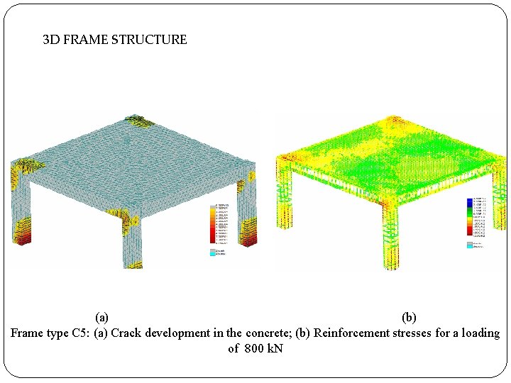
3 D FRAME STRUCTURE (a) (b) Frame type C 5: (a) Crack development in the concrete; (b) Reinforcement stresses for a loading of 800 k. N
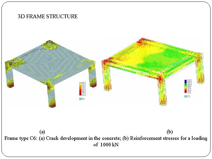
3 D FRAME STRUCTURE (a) (b) Frame type C 6: (a) Crack development in the concrete; (b) Reinforcement stresses for a loading of 1000 k. N
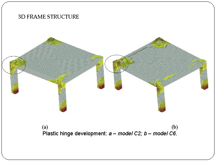
3 D FRAME STRUCTURE (a) (b) Plastic hinge development: a – model C 2; b – model C 6.
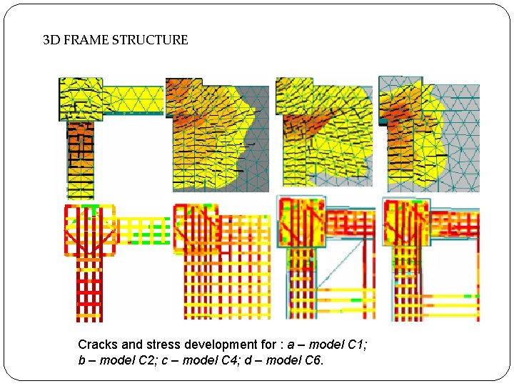
3 D FRAME STRUCTURE Cracks and stress development for : a – model C 1; b – model C 2; c – model C 4; d – model C 6.
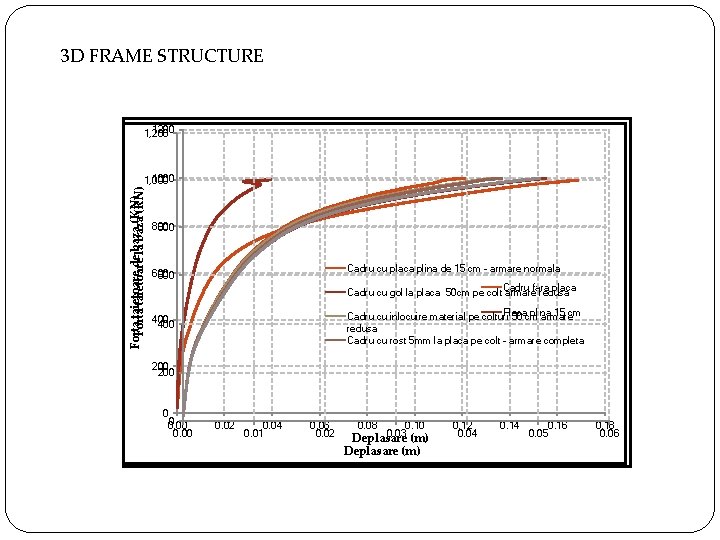
3 D FRAME STRUCTURE 1200 1, 200 Forta taietoare dela baza (KN) Forta taietoare baza (KN) 1000 1, 000 800 Cadru cu placa plina de 15 cm - armare normala 600 Cadru fara placa Cadru cu gol la placa 50 cm pe colt armare redusa Placa plina 15 cm Cadru cu inlocuire material pe colturi 50 cm armare redusa Cadru cu rost 5 mm la placa pe colt - armare completa 400 200 0 0 0. 00 0. 02 0. 04 0. 01 0. 06 0. 02 0. 08 0. 10 0. 03 (m) Deplasare (m) 0. 12 0. 04 0. 16 0. 05 0. 18 0. 06
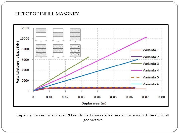
EFFECT OF INFILL MASONRY Capacity curves for a 3 level 2 D reinforced concrete frame structure with different infill geometries
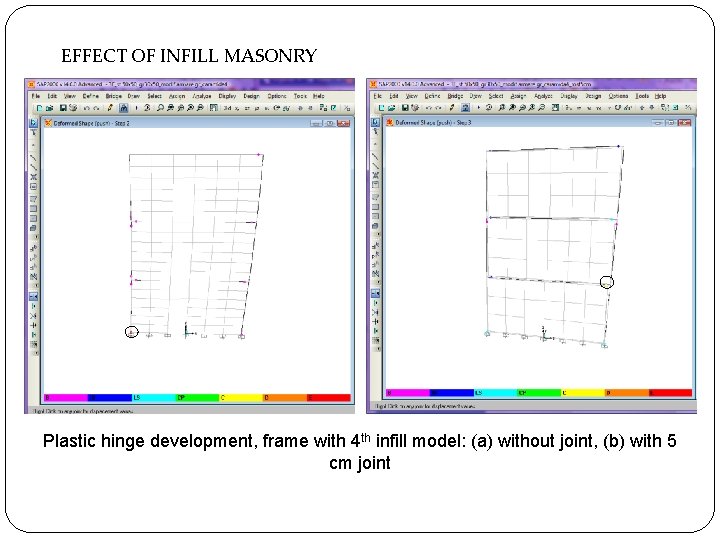
EFFECT OF INFILL MASONRY Plastic hinge development, frame with 4 th infill model: (a) without joint, (b) with 5 cm joint
Case study on directing plastic hinges from columns into beams Scientific Team: asist. dr. ing. Ioana Olteanu prof. dr. ing. Alex Barbat (from UPC, Barcelona, Spain) ing. Radu Canarache Iasi, Mai 2013