CARMA The Combined Array for Research in mmwave

CARMA: The Combined Array for Research in mm-wave Astronomy Tony Beasley NSF Review, July 16 2002

Introduction n n n Two decades – OVRO/BIMA arrays have pioneered field of mm interferometry Talks: remarkable achievements & ongoing development programs of individual facilities Early 90’s: shared interest in Sci/Ed benefits of merging the arrays led to “CARMA concept” Today: CARMA Project underway: overview 1 st: Technical/infrastructure development already directed towards new array – context Note: URO proposal under consideration includes transition and early CARMA operations

Project Goal Build a new mm array emphasizing n New science n n n Improved continuum/spectral-line sensitivity Unique: Image on all angular scales: HR, Wide FOV Operational flexibility Student training - “hands-on” New instrumentation & observational techniques Public outreach
 n six 10. 4")
Key Features of CARMA n Heterogeneous array (850 m 2) n six 10. 4 m antennas - OVRO n nine 6. 1 m antennas - BIMA n eight 3. 5 m antennas – Uni. Chicago SZA n Use four configs: 100 m – 1500 m + SZA n Imaging over wide range of angular scales: n CARMA: 0. 2 -30”, SZA: 0. 5 -3’ More antennas High-fidelity imaging + snapshot Mosaicing n

Science Drivers n n n Studies of circumstellar/protoplanetary disks, stellar outflows, evolved stars Examine environments of nearby & distant galaxies Explore Solar System: Sun, planets, comets, KBOs Probe astrochemistry of ISM, IPM Image distant universe: high-redshift galaxies Cosmology experiments (other talks…) CARMA: address key research areas + complement new instruments (NGST/EVLA/CELT/ALMA)

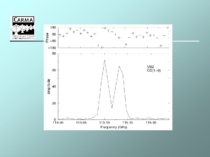
Example: high-resolution imaging of CO in the Virgo Cluster
 Angular Resolution & Line Sensitivity")
CARMA Sensitivity Continuum Sensitivity (4 GHz BW, 2 pol) Angular Resolution & Line Sensitivity (1 km/s channel, 1 -pol) 230 GHz 100 GHz Freq GHz 1 min m. Jy 5 -hr m. Jy Confi g Bea m ” 1 min K 5 -hr K 100 0. 7 0. 0 4 D 6. 3 0. 4 0. 02 2. 7 0. 04 230 2. 2 0. 1 C 2. 5 2. 4 0. 1 1. 1 4. 4 0. 26 (345 ) 12. 0 0. 7 B 1. 0 14. 8 0. 4 36 2. 1 A 0. 4 92 5. 3 0. 2 144 8. 4 Summary Mins ~ K Hrs ~ sub-K

High-Altitude Site n n Lower atmospheric opacity, better phase stability: increase in observing time, speed Required: >7000’, 2 -km baselines, 400 -m central area, year-round access, low snow Owens Valley – high, dry locations with suitable topography – White/Inyo Mtns. 7000 -8000’ : factor of two improvement in opacity statistics over existing sites (mean , number of days < given etc. ) – x 4 integration time, year-round observing

Site Selection n n Initial candidate – Upper Harkless Flat 1996+ Caltech studies, development Opposition – site dropped in 2001 strategy: analyze range of sites Initial sample three candidates n n n Juniper Flat (7900’) Cedar Flat (North & East -7300’) Lower Harkless Flat (7100’)


Juniper Flat – 7900’

Juniper Flat – 7900’

Cedar Flat East – 7300’

Cedar Flat North – 7300’

Lower Harkless Flat – 7100’

Percentiles 25% < 0. 12 50% < 0. 16 75% < 0. 28 OV: Regional results consistent

Site Acquisition n n n All sites on National Forest – federal NEPA UC participation – state CEQA Result: joint EIS/EIR document Considered: Botany/Wildlife/Cultural issues Strong community support Residual opposition: CNPS, ESAS, Big Pine tribe In general: CARMA strategy good, land use in the OV is complex issue…

Process Timeline n n n n SUP Application to INF – October 2001 NEPA/CEQA Formal Initiation – March 2002 Public Scoping process – June 2002 (draft EIS/EIR doc: October 2002) (final EIS/EIR: December 2002) (ROD/appeal period – March 2003) Site access: Spring 2003+

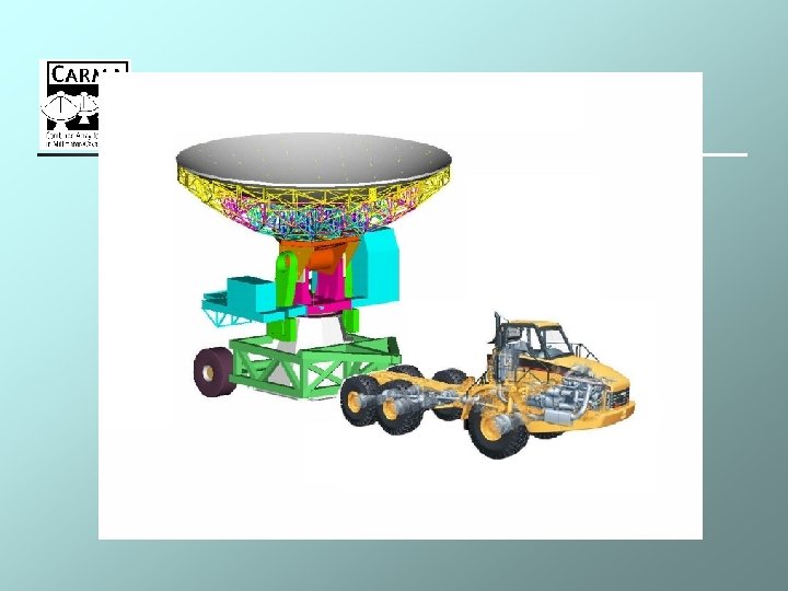
Array Developments n n n n New Site Antenna Transporter + Relocation plan First light: COBRA-based 4 GHz FPGA Correlator + 8 GHz SZA continuum (flexible subarraying) SOA integrated 22 GHz WVR phase correction LO/IF system – HEMT/SIS/MMIC? receivers New computing & archive system Upgrades: antenna drives & cryogenics, telemetry Development options: single dish, wideband BIMA IFs, polarization capability (other talks. . )

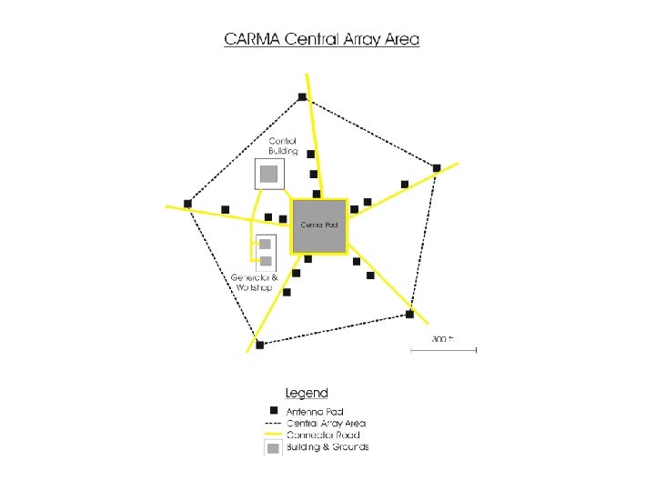
Site layout

VRML simulation

Relay Station

Operations Model n n n Site-dependent… General: similar to OVRO/BIMA model – observers/students/postdocs run array Generate own power - diesel Important: utilize/enhance existing infrastructure (kitchen, dorms, engineering facilities) Time allocation/observing policies: under consideration by SSC

Consortium Structure CARMA BOARD Science Steering Committee CARMA Director Project Manager A. Beasley Antennas Transporter Woody Plambeck n n Relocation WVR Computing LO/IF Correlator Site Fleming Woody Snyder Harris Woody Plambeck Scott Pound Crutcher Plambeck Lamb Hawkins Beasley Working Groups: Science, Hardware, Software, Configuration Distributed design/development via email, weekly telecons, f 2 f meetings, visits Website: www. mmarray. org - info, document archive July 2002 – Project plan revision underway
 Correlator Site WVR Environmental Management/Admin Transporter Computing BIMA Relocation Technical Developments")
Budget $M (2002) Correlator Site WVR Environmental Management/Admin Transporter Computing BIMA Relocation Technical Developments 15% Contingency (July 2002) n n 1. 8 4. 3 0. 5 1. 0 2. 0 0. 7 0. 3 1. 2 0. 8 1. 9 $14. 5 M Funding: Caltech $5 M, BIMA $5 M, NSF $2. 3 M (+$2 -3 M TBI) Staffing for project development: URO operations grants

Schedule n n n n Design/analysis/scoping phase - past year BIMA/OVRO upgrades/retrofits - Fall 2002 New technical developments - Fall 2002 Milestone: Correlator PDR – November 2002 Site Award/construction – Spring 2003 Move OVRO to high site – Spring 2004 BIMA relocation – Spring/Fall 2004 Full Operations – Summer 2005

CARMA n n Next three years – upgrades, new technical developments & transition to single instrument/observatory operations - busy Maintaining/enhancing staffing levels critical to support project development Outstanding issue - site process – progressing well, resolution early next year CARMA: common vision/shared future, excited project & array potential

OVRO images
- Slides: 34