Capacitor Training Duck River Electric Membership Corp Doug

Capacitor Training Duck River Electric Membership Corp. Doug Simpson

�CAPACITOR FUNDAMENTALS �CAPACITOR USES �DREMC Practices �Capacitor Safety Welcome and Introduction

�A capacitor is a device that accepts an electrical charge, stores it, and then releases the charge when desired. �A good comparison to a capacitor would be a battery. CAPACITOR FUNDAMENTALS

When talking about Capacitors… �KVAR - is the “measure of” good offset a capacitor will provide against bad inductance. It is not the name for a Capacitor, only a measurement. �The term Bank refers to each phase being involved just like with a transformer bank, A, B, & C. CAPACITOR FUNDAMENTALSVocabulary

�In its simplest form, a capacitor consists of two metallic plates separated by an air gap. �Only three factors govern how much energy can be stored in a capacitor. 1. How big are the plates? 2. How close are they together? 3. What insulating material separates them? CAPACITOR FUNDAMENTALSWhat does a Capacitor consist of?

�Basically, the larger the surface of the metallic plates and the closer they are together, the more energy the capacitor can store. �If the space between the plates is filled with different insulating material, such as Kraft paper or oil, the capacity will be greater than with air. CAPACITOR FUNDAMENTALS- What a Capacitor consists of continued…
. 2. Reducing Line Losses (or VAR Control). 3.")
Improving Power Factor (or VAR Control). 2. Reducing Line Losses (or VAR Control). 3. Decreasing Voltage Drop. 1. DREMC uses Capacitors for VAR control on our system, not decreasing voltage drop. CAPACITOR USESWhat are the Primary uses for a Capacitor?
. Reactive power is the unusable")
Real power is usable power measured as k. W(kilowatt). Reactive power is the unusable power measured as k. VAR (kilo Volt Amp Reactive). Apparent power is the true measured value on the power system measured as k. VA(kilo Volt Amp). It is made up of two components, real power (expressed in k. W) and reactive power (expressed in k. VAR). (k. W) (k. V A) CAPACITOR USESPower Factor (k. VAR)
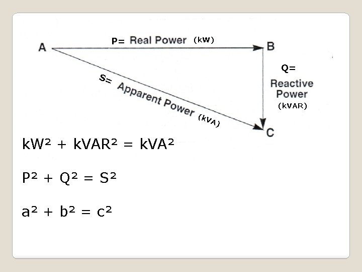

To understand what a capacitor does, you will have to understand what is meant by POWER FACTOR (pf). Pf= Real Power(k. W) = 1 (Ideal Case) Apparent Power(k. VA) CAPACITOR USESPOWER FACTOR…
 Reactive Power Real Power CAPACITOR")
Pf= Real Power Apparent Power = 1 (Ideal Case) Reactive Power Real Power CAPACITOR USESPOWER FACTOR Continued…

Imagine yourself at Point A wanting to get to Point C, but due to obstructions you must first walk to Point B and then to Point C. The energy you expended walking to Point C was increased because you could not take the direct course. CAPACITOR USES- Line Losses and Voltage Drop

Power Systems act just like our example. The reactive power ( the extra steps from Point B to Point C) makes the power system work harder. To offset the this reactive power, capacitors are added to the system to make Points B and C closer together. This makes the apparent power value closer to the real power value. Remember, the Ideal case is for the apparent power and the real power to equal each other. This would make the power factor equal 1. CAPACITOR USES- Line Losses and Voltage Drop Continued

1. Equipment may have to work harder and will not last as long because of line losses. Capacitors help the equipment work better because the equipment is not overburdened and, in turn, will last longer 2. High k. VAR demands cause excessive voltage drop. Capacitors help to correct this. 3. A low power factor may cause an unnecessary increase in system losses. Remember the ideal power factor is 1. CAPACITOR USES- Line Losses and Voltage Drop Continued

�FIXED BANKS- The Capacitor bank stays “online” all the time and should have operable load break fuse disconnects. �SWITCHED BANKS- On a circuit are switched as TIME/VOLT. This means the Capacitor bank switches on and off by TIME and can be over ridden by VOLTAGE either too high or too low. They must have operable “oil switches” on these banks. DREMC Practices CAPACITOR BANK TYPES
 DREMC")
Fixed Capacitor Bank Switched Capacitor Bank Load Break Fuse Disconnect “Oil Switch” (Vacuum) DREMC Practices CAPACITOR BANK TYPES

�SUBSTATION SWITCHED BANKS- �Are switched at the Manchester 161 by a S&C Intellicap only on voltage at 8, 100 k. VAR each bank, switches 318 and 328. �Are switched at Unionville by a SEL relay on Power Factor normally and on VOLT when the Mobile is in service, because it does not have a LTC, at 1, 800 k. VAR each bank, switches 318, 328, 338, & 348. DREMC Practices CAPACITOR BANK TYPES

�DREMC stocks 100 k. VAR and 200 k. VAR capacitors �A 600 k. VAR bank means that A, B, & C Ø each have one 200 k. VAR capacitor mounted in the capacitor rack. 200 k. VAR times 3 phases = 600 k. VAR DREMC Practices CAPACITOR BANK SIZE MATH

�When Fusing both bank size and voltage will influence your proper choice. � 7. 2 k. V, 300 k. VAR bank= 20 T fuse � 7. 2 k. V, 600 k. VAR bank= 40 T fuse � 14. 4 k. V, 600 k. VAR bank= 20 T fuse � 14. 4 k. V, 1, 200 k. VAR bank= 40 T fuse DREMC Practices Bank Sizes and Proper Fusing

When manually opened or closed, the control will delay the intended action for a total of 30 seconds. USE THIS TIME TO GET IN A SAFE POSITION. 2. When opened automatically or manually, the control will block closing for 5 minutes total. 1. DREMC Practices S&C Intellicap Operation Features
 2) 3) 4) 5) DANGER READ! OPEN CAPACITOR SWITCH. OPEN MAIN FUSES WITH")
1) 2) 3) 4) 5) DANGER READ! OPEN CAPACITOR SWITCH. OPEN MAIN FUSES WITH AN INSULATED STICK. WAIT 5 MINUTES. AFTER 5 MINUTES, BLEED OFF CAPACITORS TO GROUND USING AN INSULATED STICK. JUMPER BOTH BUSHINGS TOGETHER AND THEN TO TANK. Capacitor Safety. Procedure

• ALWAYS Ground the Capacitor with a heavy wire jumper from bushing to TANK to keep the capacitor SHORTED for SAFETY! • Do not lift the capacitor by the bushings or shorting wire to keep from breaking the bushings for safe handling. Capacitor Safety. Handling Procedures

ALWAYS utilize load break devices when removing a capacitor bank from service. • USE A LOAD BUSTER TOOL WHEN YOU CAN FOR ANY MALFUNCTIONED LOAD BREAK DEVICE ON A CAPACITOR BANK, DO NOT ATTEMPT TO BREAK LOAD OTHERWISE! • Capacitor Safety. Removing From Service
- Slides: 23