Capacitance PHY 2049 Chapter 25 Chapter 25 Capacitance


 d Air or Vacuum E -Q Area A")


")


pf V series C 3 C 1=12. 0")


 sign because E and ds are in OPPOSITE directions.")
 sign due to switch of limits.")
- Slides: 32
Capacitance PHY 2049 Chapter 25
Chapter 25 Capacitance In this chapter we will cover the following topics: -Capacitance C of a system of two isolated conductors. -Calculation of the capacitance for some simple geometries. -Methods of connecting capacitors (in series , in parallel). -Equivalent capacitance. -Energy stored in a capacitor. -Behavior of an insulator (a. k. a. dielectric) when placed in the electric field created in the space between the plates of a capacitor. -Gauss’ law in the presence of dielectrics. (25 - 1)
Capacitors
Capacitor o Composed of two metal plates. o Each plate is charged n one positive n one negative o Stores energy SYMBOL
A simple Capacitor TWO PLATES WIRES Battery
INSIDE THE DEVICE
What is STORED in the capacitor? o o o An Electric Field Energy Charge All three None of these
Two Charged Plates (Neglect Fringing Fields) d Air or Vacuum E -Q Area A V=Potential Difference +Q Symbol ADDED CHARGE
Where is the charge? - Q- d Air or Vacuum E Area A V=Potential Difference + + + +Q AREA=A s=Q/A
One Way to Charge: o Start with two isolated uncharged plates. o Take electrons and move them from the + to the – plate through the region between. o As the charge builds up, an electric field forms between the plates. o You therefore have to do work against the field as you continue to move charge from one plate to another.
Capacitor
More on Capacitors d Air or Vacuum -Q E +Q Area A Gaussian Surface V=Potential Difference Same result from other plate!
DEFINITION - Capacity o The Potential Difference is APPLIED by a battery or a circuit. o The charge q on the capacitor is found to be proportional to the applied voltage. o The proportionality constant is C and is referred to as the CAPACITANCE of the device.
UNITS o A capacitor which acquires a charge of 1 coulomb on each plate with the application of one volt is defined to have a capacitance of 1 FARAD o One Farad is one Coulomb/Volt
Continuing… o The capacitance of a parallel plate capacitor depends only on the Area and separation between the plates. o C is dependent only on the geometry of the device!
After the switch is closed, how much charge passed through the capacitor? V o o C/V V/C CV C+V
P S N (25 - 6)
Units of e 0 pico
Simple Capacitor Circuits o Batteries n Apply potential differences o Capacitors o Wires n Wires are METALS. n Continuous strands of wire all at the same potential. n Separate strands of wire connected to circuit elements may be at DIFFERENT potentials.
NOTE o Work to move a charge from one side of a capacitor to the other is = q. Ed. o Work to move a charge from one side of a capacitor to the other is q. V o Thus q. V = q. Ed o E=V/d As before
TWO Types of Connections SERIES PARALLEL
Parallel Connection V CEquivalent=CE
Series Connection q V -q C 1 q -q C 2 The charge on each capacitor is the same !
Series Connection Continued q V C 1 -q q -q C 2
More General
Example C 1 C 2 (12+5. 3)pf V series C 3 C 1=12. 0 uf C 2= 5. 3 uf C 3= 4. 5 ud
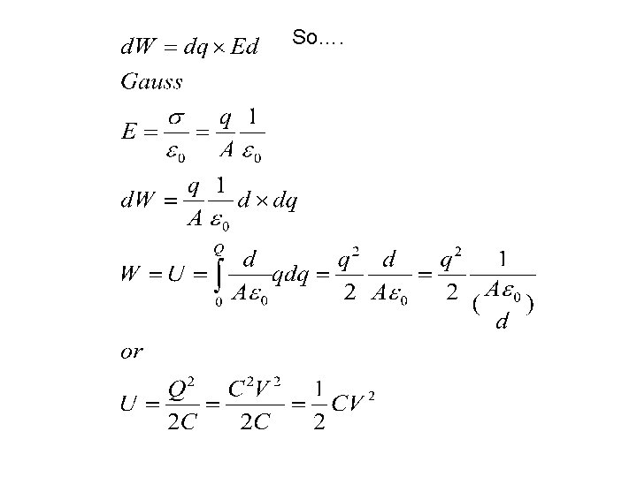
More on the Big C E=e 0 A/d +dq +q -q o We move a charge dq from the (-) plate to the (+) one. o The (-) plate becomes more (-) o The (+) plate becomes more (+). o d. W=Fd=dq x E x d
Not All Capacitors are Created Equal o Parallel Plate o Cylindrical o Spherical
Spherical Capacitor
Calculate Potential Difference V (-) sign because E and ds are in OPPOSITE directions.
Continuing… Lost (-) sign due to switch of limits.