Canadas National Laboratory for Particle and Nuclear Physics

Canada’s National Laboratory for Particle and Nuclear Physics Laboratoire national canadien pour la recherche en physique nucléaire et en physique des particules 2. 9 MW Cyclotron Main Magnet Power Supply Dan Louie | TRIUMF Owned and operated as a joint venture by a consortium of Canadian universities via a contribution through the National Research Council Canada Propriété d’un consortium d’universités canadiennes, géré en co-entreprise à partir d’une contribution administrée par le Conseil national de recherches Canada

TRIUMF stands for TRI University Meson Facility Founded by University of British Columbia, Simon Fraser University, University of Victoria 43 Years Ago Full Members: Carleton University of Guelph Queen’s University Simon Fraser University of Alberta University of BC University of Manitoba Université de Montréal University of Toronto University of Victoria York University Associate Members: University of Calgary Mc. Master University Saint Mary’s University of Regina

TRIUMF is located on the campus of University of British Columbia.

TRIUMF Accelerators § 500 Me. V Hcyclotron since 1974 ISAC-II SRF Linac § ISAC-I accelerates rare-isotopes 2001 DTL RFQ ARIEL Facility § ISAC-II first experiment 2007 ISAC-I ISAC Targets § ARIEL (e. Linac) begins 2010 ISAC: Isotope Separator and Accelerator ARIEL: Advanced Rare Isotop. E Laboratory 50 Me. V Electron Linac 500 Me. V Cyclotron 4

TRIUMF Power Supplies Distribution Proton Accelerators Cyclotron: Trim Coils, 5 k. W, (max. 85 Amperes) Harmonic Coils, 5 k. W, (max. 85 Amperes) Main Magnet, 2. 9 MW, (max. 26700 Amperes) Beamlines: Dipoles, 100 k. W, (max. 1250 Amperes) Quadrupoles, 100 k. W, (max. 1000 Amperes) Steerers, 1. 5 k. W, (max. 30 Amperes) Total: Electron Linac Beamlines: Dipoles, 20 k. W, (max. 400 Amperes) Quadrupoles, 1. 6 k. W, (max. 60 Amperes) Steerers, 50 W, (max. 5 Amperes) Total: 88 22 1 30 225 183 549 10 54 126 190 5

Cyclotron Facts Function : Accelerates H- ion beam. Average beam current 350 u. A, up to 520 Me. V Vacuum Tank: Diameter: about 18 meters Pressure achieved: less than 5 X 10 -8 Torr Main Magnet: Type : Sector-focussed electro-magnet Configuration : " Pinwheel " , 6 -sectors trailing CCW looking from top (see TRIUMF logo) Pole diameter: ~18 meters Weight: 4000 Tons Coils: 30 turns (15 upper and 15 lower) Characteristics: 0. 004 ohm, 0. 12 H Normal Operating Power: 18400 Amperes at 75 Vdc. Field : 5608 Gauss (normal operation) 6
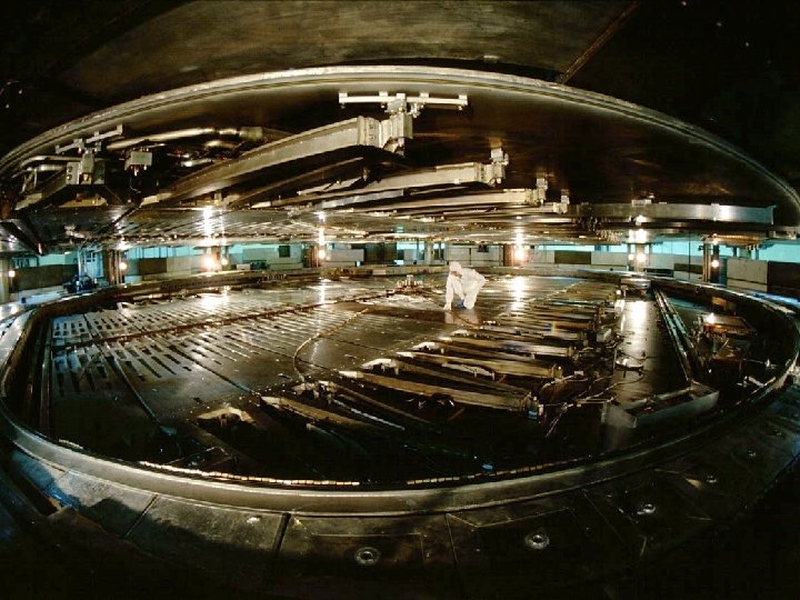

Cyclotron Magnet 12/4/2020 Bottom half of main magnet poles and coil 8

Cyclotron Magnet Power Supply • • 12/4/2020 Linear, Series Pass Regulator Max Output Voltage: 110 Vdc Max Output Current: 26, 700 Amps Max Output Power: ~2. 9 MW Current Stability: 2 ppm Magnetic Field Stability: ~1 ppm with external field compensation In operation since: 1974 Made by Alpha Scientific, California, USA 9

Cyclotron Magnet Power Supply 12/4/2020 10

Cyclotron Magnet Power Supply 12/4/2020 11

Cyclotron Magnet Power Supply – Major Components 12/4/2020 12

Cyclotron Magnet Power Supply – Control Cabinet Analog Meter: AC Current, Output Volt, Output Current, Ground Current. Many Interlock Indicator Lights. Supply has many internal fault protection. Very stable voltage reference. Output is set via a 24 -bit parallel digital interface. 12/4/2020 13

Cyclotron Magnet Power Supply – Rectifier Cabinet Contains: Duel AC transformers Rectifier Diodes Inter-phase Transformer Choke Inductor Capacitor Filter 12/4/2020 14

Cyclotron Magnet Power Supply – Duel AC Input Transformers T 1: Delta – Delta arrangement 2255 k. VA, 3 phase, 60 Hz Primary 1174 V, 1074 A Secondary 119 V, 10890 A T 2: Delta – Wye arrangement 2255 k. VA, 3 phase, 60 Hz Primary 1174 V, 1074 A Secondary 119 V, 10890 A 12/4/2020 15

Cyclotron Magnet Power Supply – Transformer Water Leak • Water was found on the floor next to the transformer cabinet on April 15 th 2012. • Proton therapy was taken place at the time and scheduled for another 2 days. • Initial assessment on the evening of April 15 th indicated the leak was in the power transformer TR 1. • Decision was made to leave the power supply ON to complete patient treatment. • The power supply was immediately switched OFF after the final patient treatment on April 17 th. 12/4/2020 16

Cyclotron Magnet Power Supply – Transformer Construction Core Primary Layer Secondary Layer 12/4/2020 • Transformer has 3 layers of primary windings wrapped around the core with the secondary making up the 4 th outer most layer. • Both Primary and secondary windings constructed of ½” schedule-40 copper pipe. • Leak was located at the secondary winding of the middle phase. • Leak rate was estimated to be about 5 liters per hour. 17

Cyclotron Magnet Power Supply – Transformer Water Leak – Actions and Results • • • Conventional fix of removing and rewinding the transformer would take up to 6 months. An alternative experimental method of stopping the leak by lining the inner wall of the pipe with epoxy was employed. The company selected to perform the work is Curaflo. Calculation was performed to estimate the rise in copper temperature due to thermo insulating property of the epoxy coating. The increased in temperature was expected to be 5 degrees Celsius. Two temperature sensors were installed. One to the treated winding, the other to a nontreated winding. After a warm up period, the treated winding temperature was 38 degrees Celsius; the non-treated winding was 34 degrees Celsius. Reduction in pipe wall thickness due to erosion is relatively minimal. The contractor also noticed while the epoxy was emitting out of the pipe, the ‘gurgling’ sound made was more due to a small crack rather than a pin-hole. The speculation is that the crack was cause by a onetime mechanical stress rather than wear and tear. Treatment started on April 23 rd, main magnet supply was turned ON April 25 th. Cost of treatment was about $14, 000 Can. 12/4/2020 18

Cyclotron Magnet Power Supply – Rectifier Diodes Assembly Diode rating: 300 V – 1700 Amp The outputs of T 1 and T 2 are rectified by duel six-phase full-wave diode assembly. The two outputs are connected in parallel to the common load through an interphase transformer. This combination results in 12 -phase rectification with low ripple component. 12/4/2020 19

Cyclotron Magnet Power Supply – Interface Transformer and Choke Inter-phase Transformer: 26700 Amp 160 Vdc Working Choke Inductor 5 u. H 26700 Amp 160 Vdc Working 12/4/2020 20

Cyclotron Magnet Power Supply – Regulating Cabinet Contains: Four Transistor Banks Current Shunt DC Bus Bars Error Amp PCB 12/4/2020 21

Cyclotron Magnet Power Supply – Transistor Banks Multiple stages – current gain of more than 1 million from error amp to output. Four transistor banks running in parallel in final output stage. 2000 transistors make up the four banks. Supply will trip OFF if more than three transistors have failed. 12/4/2020 22

Cyclotron Magnet Power Supply – Precision Shunt Current Rating: 26700 Amps Output Signal: 1 Vdc Full Scale Stability: 1 ppm Temperature Compensated Dissipates about 20 k. W during normal operation 12/4/2020 23

Cyclotron Magnet Power Supply – Cyclotron DC Bus Bars Aluminum bus bar – cross section 1” X 18” Cooled by aluminum low conductivity water. 12/4/2020 24

Cyclotron Magnet Power Supply – Free Wheeling Diodes 40 high power diodes connected in parallel to main magnet coils. 20 MJ of stored energy in the magnet during normal operation. 12/4/2020 25

Cyclotron Magnet Power Supply – Magnetic Field Compensation Stable output from the power supply does not guarantee stable magnetic field. Physical characteristics of the magnet and environmental factors contribute to long term magnetic field drift. The signal from a pickup coil is integrated and fed back to the control loop of the supply to counteract external disturbances. 12/4/2020 26

Cyclotron Magnet Power Supply – Pickup Coil compensation Graph shows Nuclear Magnetic Resonance (NMR ) probe 5608. 2 Gauss. Compensation was disabled for first hour. Long term drift for cyclotron magnetic field is < 1 ppm. Compensation is disabled momentarily when adjustment is done on the main magnet or any of the trim and harmonic coils. 12/4/2020 27
")
Cyclotron Magnet Power Supply - Replacement Klaus Reinger (former TRIUMF Power Supplies Group Leader) authored the technical specifications for new power supply in March 2015. Output Requirements: Maximum Output Power Maximum Output Current Maximum Output Voltage Normal Output Current Range Overall Stability 12/4/2020 1. 6 MW DC continuous 20 000 Amp DC 80 Volt DC 17 000 to 20 000 Amp DC +/- 2 ppm of 20000 Amp for range of 17 000 to 20 000 Amp 28

Cyclotron Magnet Power Supply - Replacement The specifications was part of a Request for Proposal published in April 2015. The following companies returned proposal: OCEM (Bologna, Italy) Danfysik (Taastrup, Denmark) Alpha Scientific (California, USA) JEMA (Gipuzkoa, Spain) EEI (Vicenza, Italy) TEMES (Warngau, Germany) Price range $930 000 to $1 900 000 CAN 12/4/2020 29

Cyclotron Magnet Power Supply - Replacement Joerg Eckoldt, DESY, was member of the proposal assessment committee. Contract was awarded to OCEM Power Electronics, Bologna, Italy. Initial design report was accepted by TRIUMF March 2016. Construction has started. Testing at OCEM facility in November 2016. Shipped to TRIUMF December 2016. Installation begin during scheduled shutdown in January 2017. 12/4/2020 30

Cyclotron Magnet Power Supply Thank You ! Gracias ! 12/4/2020 31
- Slides: 31