Calibration of the Wright Brothers 1901 Lift Balance

Calibration of the Wright Brother’s 1901 Lift Balance l Joshua Branch 7 th grader at Saint Margaret of York Catholic School l Richard Branch Dynamic Technology Solutions l David Pinella Aero. Logic www. aerologic. com

“Dad, I’d like to build a reproduction of the Wright Brother’s wind tunnel for my science fair project. ” - Joshua Branch, November 2003

7 th Grade Science Fair l This started out as a junior high school Science Fair Project, but turned into a history lesson that answered questions that had not been asked for 100 years l Joshua was the initial inspiration for this project. – We didn’t know too much about the Wind Tunnel, but after some research, we decided that it would be a worthwhile project to undertake l Plans for the wind tunnel and balances were purchased from The Wright Brothers Aeroplane Company in West Milton, Ohio

Wind Tunnel Construction started in February – Josh was an equal contributor during the entire construction phase – Wooden tunnel was easy to build – Balance was built from brass purchased from local hobby shop. Next time we will use old hacksaw blades and bicycle spokes. – The shroud was most difficult component for us to build l Josh learned about metalworking, pattern layout and MIG welding during this phase of construction

Wind Tunnel Construction l Airflow source – We used a 24 inch, 4 bladed fan and 1/2 horsepower motor purchased from an industrial supply company l l Measured 20+ MPH air flow through tunnel We studied the lift balance to develop an understanding of how it works – Josh learned about balancing static forces and some trigonometry

Results of Science Fair Project l Hypothesis – A curved airfoil will produce more lift than a flat plate l As hypothesized, the curved airfoil produced more lift.

Results of Science Fair Project l School Science Fair – Superior rating l District Science Fair at University of Cincinnati – Superior rating l State Science Fair at Ohio State University – Superior rating – Won award for “Outstanding project in engineering and space sciences, mathematics and computer science, and environmental science” sponsored by the United States Air Force. l This project cost my Dad more money that the Wright Brothers spent to invent the first airplane.

Wright Brothers Wind Tunnel History Lesson

Why did the Wright’s build a wind tunnel? l During their trips to Kitty Hawk in 1900 and 1901, they did not achieve the lift that they had calculated based on data they obtained from Otto Lilienthal’s work. – V 2 (velocity squared) and S (planform area of wing) – Either Smeaton’s Coefficient (k) or Cl (Coefficient of Lift) were wrong – After returning from Kitty Hawk in the summer of 1901 l l Based on their gliding experiments, they determined that the value they were using for Smeaton’s Coefficient was incorrect The decided to build a wind tunnel that would allow them to measure Cl for different wing profiles – They designed and built a wind tunnel and two instruments that they used to measure lift and drag

The Lift Balance l A delicate instrument made from old hacksaw blades and bicycle spokes that allowed the Wright’s to measure the lift of a test specimen
 to the desired")
Operation of the Lift Balance - Setup Set the model (airfoil) to the desired angle of attack and turn on the airflow l The upper and lower beams move together because the friction sleeve is engaged l The crossbeams and arms move due to the torques created by: l – Drag forces on fingers (Df) – Lift on model (Lm) – Drag on model (Dm) l When the torque created by the drag on the fingers and the drag on the airfoil is balanced by the torque created by the lift on the airfoil, equilibrium is achieved, and the balance stops moving

Operation of the Lift Balance - Eliminate Dm l Disengage friction sleeve, and move the upper crossbeam until the arms are parallel with the airflow – This eliminates the drag on the airfoil from the measurement The torque due to the lift on the airfoil is then equal to the torque due to the drag on the fingers l Write the torque balance about the pivot point l

Significance of 1901 Wind Tunnel Work l The lift and drift balances marked a significant departure from instruments used by others to measure lift and drag l The Wrights were the first to systematically collect specific data on a wide range of prospective wing shapes l They were the first to use an instrument to obtain aerodynamic data that could be used directly in the design of an airplane l They possessed more data and understanding of cambered surfaces than all of their predecessors put together l Their wind tunnel experiments contributed significantly to their ultimate success to design and build the first successful airplane
 1902 Glider")
Results of Wright’s Wind Tunnel Work 1901 Glider (Before Wind Tunnel Work) 1902 Glider (After Wind Tunnel Work)

Our Wind Tunnel Work

Drag Fingers

Drag Fingers The drag fingers on our version of the lift balance were built according to the plans l As we progressed through the project, we started to ask ourselves questions about the drag fingers: l – Why are the drag fingers angled backwards 40°? – Why do the drag fingers have such strange shapes? l How did the Wrights determine the correct shapes for the drag fingers? – Available references indicate that the drag fingers are equivalent to a plate with an area of 8 in 2, placed 90° to the air flow l The area of the drag fingers is not 8 in 2 , and they are not placed 90° to the airflow – Modern literature states that the Wright’s data was accurate to within a “few percent”. To achieve this, they must have configured the drag fingers correctly. How did the Wrights achieve that? l Answers to our questions did not seem to be readily available, but we suspected that some sort of calibration was necessary

National Air and Space Museum l We contacted Dr. John Anderson in February/March, 2004 regarding the 40° angle of the drag fingers. Dr. Anderson conferred with Dr. Tom Crouch – They pointed out that the Wrights constantly refer to the drag fingers as being “normal to the flow” l We think that “normal to the flow” means the 4 bar mechanism keeps the bar holding the drag fingers and the test specimen “normal” to the flow l We don’t believe that this comment refers to the bending of the drag fingers, i. e. keeping the fingers themselves “normal” to the flow l Dr. Anderson’s email referenced Wilbur Wright’s letter to Octave Chanute written on January 19, 1902 – We had not read that letter before Dr. Anderson brought it to our attention

Wilbur's letter to Octave Chanute on January 19, 1902 l Letter included – Explanation of lift balance operation – Diagram of lift balance with components labeled – Picture of lift balance l Were the drag fingers really bent back 40°? – Using the picture included in the letter, and known dimensions of the balance, we scaled the drag fingers in the photograph and showed that the drag fingers were bent back approximately 40° when this picture was taken in 1901.

Wilbur's letter to Octave Chanute on January 19, 1902 l Referring to Wilbur’s description of the lift balance – ”The resistance planes RRRR are used instead of a single square plane to avoid deflecting the wind which strikes the Surface S. They have no definite area themselves, but along with cross piece C have a pressure equal to that of a square plane of 8 sq. inches mounted at the place where S appears in illustrations. " l “No definite area themselves…. ” – We believe that this statement alone indicates that the lift balance must have been calibrated l We wanted to prove that the balance was calibrated

How can we determine if the lift balance was calibrated? l We read books on the Wright Brothers – “The Bishop’s Boys” by Dr. Tom Crouch (National Air and Space Museum) – “Visions of a Flying Machine” by Dr. Peter L. Jakab (National Air and Space Museum) – “History of Aerodynamics” by Dr. John Anderson (University of Maryland a guest curator at the National Air and Space Museum) – “The Papers of Orville and Wilbur Wright” by Marvin W. Mc. Farland Searched the Internet l Contacted Wright Historians l – National Air and Space Museum – Wright State University – Library of Congress – Franklin Institute – Mr. Ken Hyde, founder of The Wright Experience

Wright State University Initial contact with Jane Wildermuth on May 11, 2004 l She invited us to visit Wright State to review the Wright Brothers material in their Special Collections and Archives Library l – She also suggested we review their Max Baker Collection

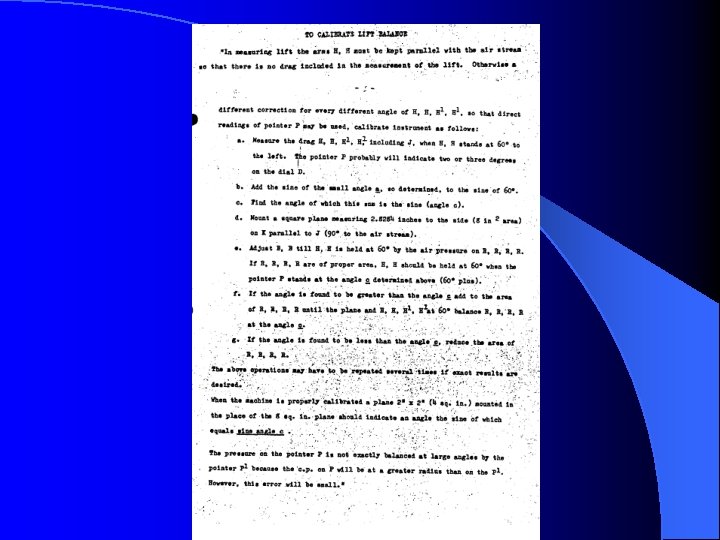
Max Baker Collection While reviewing the Max Baker Collection, we found what looked like a draft of a unpublished technical paper with a section entitled “To Calibrate Lift Balance” l We also found a picture that refers to a “Calibrating Surface” l

To Calibrate Lift Balance From the Max Baker Collection l “In Orville’s own words” l – Baker does not indicate the source of Orville’s writing l l l Diary? Letter? Court case documents?

Understanding Orville’s description of the calibration procedure l Orville’s words were initially confusing – Undocumented terminology was used – Some incorrect terminology was used – Ambiguous terminology was used l We worked several weeks to develop an understanding of the procedure – Hit several dead ends along the way l Eventually, we have developed an understanding of the procedure – Verified mathematically – Verified experimentally

Orville Wright’s written calibration procedure

Step a - Quantify the “drag error” on the arms The angle “a” is due to the drag on the arms (I) standing at 60º in the air stream l This is a measure of the “bias” error in the lift balance l Angle “a” would be zero if there was no drag on the arms (I) l Angle “a” will be different for different positions of the (I) arms (i. e. 60°, 50°, 40°, 30°, 20°, 10°) l Df = drag from H, C and RRRR l De = drag from I and K l

Step a - Quantify the “drag error” on the arms l Write the torque balance about the pivot point At 60°, the drag error, De, is quantified as:

Step b and c - Determine correction angle “c” Substitute for De Define Drp= Df = Relative Drag ratio When calibrating against an 8 in 2 reference plate, = 1. 0 for drag fingers relative to the reference plate

Physical significance of the correction angle “c” l l Observations: l l Angle “c” should be larger than 60º. This implies that the drag of the fingers should be slightly less than the equivalent 8 in 2 plate in a calibrated system. The additional drag comes from the bias error, the inherent drag of the lift balance components (H, I, etc. ) l The angle “c” is the target of a calibrated lift balance. Calibration effects are two-fold: l Adjust the drag fingers so they provide a drag “equivalent” to an 8 in 2 plate mounted perpendicular to the air flow. l Correct for drag of the lift balance mechanism that is not accounted for, i. e. the “bias” error. Angle “c” would be 60º if there was no drag on the arms (I)

Step d - Mount the Reference Plate

Step e - Adjust HH arms to 60°, measure angle “c”

Steps f and g - Adjust the Drag Fingers

Calibration Check As previously defined : = Relative Drag ratio When testing the drag fingers (that were calibrated against an 8 in 2 reference plate) using a 4 in 2 reference plate:

Calibration of our Lift Balance l Calibrate Lift Balance against 8 in 2 reference plate l Check calibration with 4 in 2 reference plate

Searching for Orville’s original writing l We want to find where Orville documented the Calibration Procedure – Potential sources l Library of Congress l Wright State University l Franklin Institute

The Library of Congress Letter from Orville Wright to Dr. Henry Allen of the Franklin Institute, 1945 l This letter, available from The Library of Congress, was pointed out to us by Jane Wildermuth from Wright State University l

The Franklin Institute We contacted John Alviti on June 3, 2004 to see if they have the enclosure that described the Method for Calibrating Lift Balance l Mr. Alviti said that their Wright Brothers collection consists of: l – Equipment – Drawings – Sketches – Scribbles l No enclosure describing the lift balance calibration method was found in the Franklin Institute’s collection

Additional information from the Library of Congress l Leonard C. Bruno of the Library of Congress responded – Their copy of the letter that refers to the Method of Calibrating Lift – – Balance is Orville’s carbon copy, and therefore does not include the enclosures Suggested that some of the enclosures were Exhibit Items in various court cases, so we should look in that section of their on-line Wright Papers Suggested referring to Mc. Farland’s book Suggested contacting the Franklin Institute Suggested we contact Ken Hyde

Wilbur Wright 1900 -1901 Diary Table of drag error due to arms as a function of angle l Page is undated, but was written after August 15, 1901 l Another indication that calibration was done in 1901 l

Still looking for the original source…. l We still have not found Orville Wright’s original calibration procedure to which Max Baker was referring

Conclusions - From a Historically Standpoint l We believe that the Wrights did calibrate the 1901 lift balance l Have we rediscovered the calibration procedure they used in 1901? – We think we have – They not only adjusted the drag of the fingers to balance that of a known reference plate, but they also attempted to minimize the error due to drag in the lift balance mechanism l Rediscovering this calibration procedure may be just a footnote to the Wright Brother’s wind tunnel work, but we believe it is another example of the brilliance of that work

Conclusions - From a Personal Standpoint l The fact that we feel we have uncovered something unknown, or at least long forgotten, gives us a great sense of accomplishment – We have learned a lot about the legacy of the Wright Brothers, research techniques, and have met many people who appreciate the Wright Brother’s accomplishments

Footnote l We made this presentation to Wright Historians at the National Air and Space Museum on August 2, 2004 – Dr. John Anderson – Dr. Peter Jakab – Dr. Tom Crouch Their feeling was that this discovery is “a bit esoteric, but still amazing” l Encouraged us to publish the findings in the AIAA “Journal of Aircraft” l – They will use their contacts at the AIAA to ensure that our work is published

Thank you for the opportunity to share this with you!
- Slides: 46