
CALIBRATION AND PERFORMANCE OF THE HAMSR INSTRUMENT DURING

CALIBRATION AND PERFORMANCE OF THE HAMSR INSTRUMENT DURING THE NASA GRIP CAMPAIGN Boon Lim*, Shannon Brown, Richard Denning, Pekka Kangaslahti, Bjorn Lambrigtsen, Jordan Tanabe, and Alan Tanner Jet Propulsion Laboratory *Contact : Boon. H. Lim@jpl. nasa. gov
Outline • • • HAMSR Overview Genesis and Rapid Intensification Processes (GRIP) Campaign Data System Thermal Environment External target – Stability, Gradients, Reflection Nominal Calibration (V 0) Receiver Temperature Calibration (V 1) Calibration Comparison (V 0 vs V 1) HAMSR Performance Summary 7/29/2011 IGARSS 2011 2

HAMSR Overview High Altitude MMIC Sounding Radiometer (HAMSR) 3 Sounding Bands (55, 118 and 183 GHz) 25 total channels Oxygen and Water Vapor Bands for Profiling Cross-Track Scanner with Ambient/Hot External Calibration Targets • Product of ESTO (IIP, ACT and AITT) • • • – Entering 15 th Year – Participated in 5 Campaigns – Integrated on 3 Aircraft 7/29/2011 IGARSS 2011 3
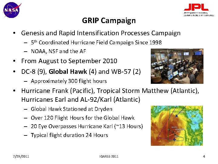
GRIP Campaign • Genesis and Rapid Intensification Processes Campaign – 5 th Coordinated Hurricane Field Campaign Since 1998 – NOAA, NSF and the AF • From August to September 2010 • DC-8 (9), Global Hawk (4) and WB-57 (2) – Approximately 300 flight hours • Hurricane Frank (Pacific), Tropical Storm Matthew (Atlantic), Hurricanes Earl and AL-92/Karl (Atlantic) – – 7/29/2011 Global Hawk Stationed at Dryden Over 120 Flight Hours for the Global Hawk 20 Eye Overpasses Hurricane Karl (~13 Hours) Typical flight duration 24 Hours IGARSS 2011 4
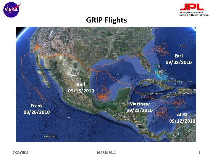
GRIP Flights Earl 09/02/2010 Karl 09/16/2010 Matthew 09/23/2010 Frank 08/28/2010 7/29/2011 IGARSS 2011 AL 92 09/12/2010 5
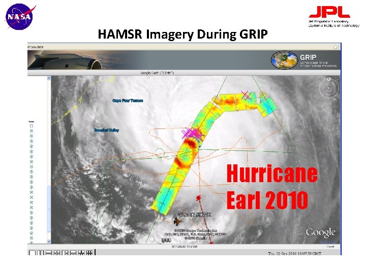
HAMSR Imagery During GRIP Hurricane Earl 2010
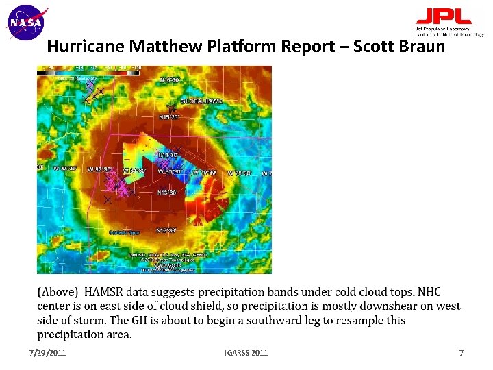
Hurricane Matthew Platform Report – Scott Braun 7/29/2011 IGARSS 2011 7
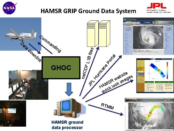
HAMSR GRIP Ground Data System mm l rta Po ne ca site s b e ge w a SR k im M o HA ck lo i qu rri JP L GHOC DF L 1 B f nl in k iles g Hu do w an din net. C Da ta Co RTM M HAMSR ground data processor
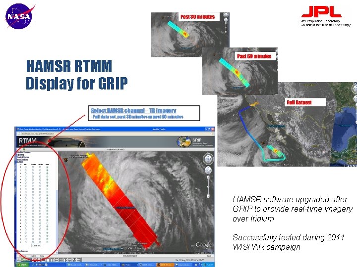
HAMSR RTMM Display for GRIP HAMSR software upgraded after GRIP to provide real-time imagery over Iridium Successfully tested during 2011 WISPAR campaign
Thermal Environment • HAMSR Sits in an Unpressurized Pod • RF Section is Thermally Insulated with Styrofoam • Temperature Controlled Heaters on the RF Plates – Thermistors Available Across the Instrument – RF Components (RF/IF LNAs, Mixers), RF Plate Temperatures, Motor, Power Supply, Digital System, Computer, Etc • Fans for Circulation of Air – On Runway if Temperatures Exceed a Threshold • At Flight Altitude (~17 km) – Temperature Typically -150 C 7/29/2011 IGARSS 2011 10
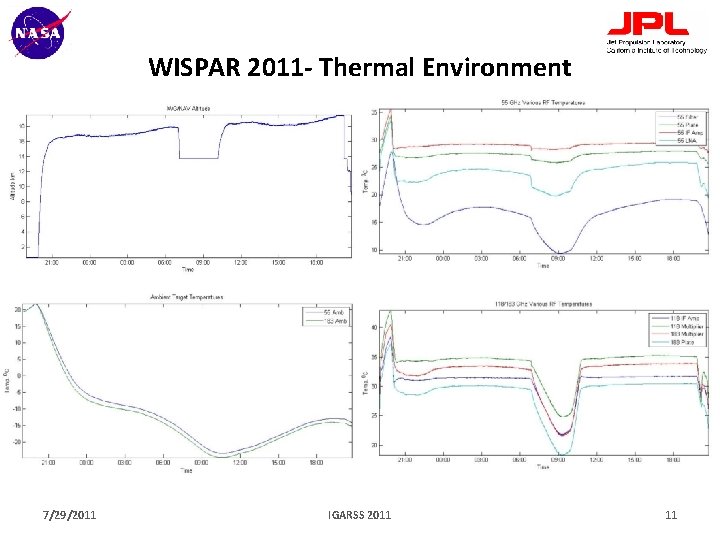
WISPAR 2011 - Thermal Environment 7/29/2011 IGARSS 2011 11
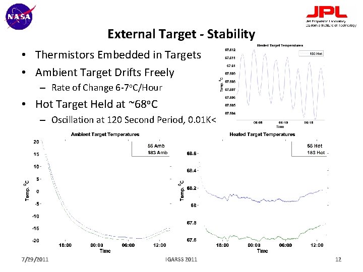
External Target - Stability • Thermistors Embedded in Targets • Ambient Target Drifts Freely – Rate of Change 6 -7 o. C/Hour • Hot Target Held at ~68 o. C – Oscillation at 120 Second Period, 0. 01 K< 7/29/2011 IGARSS 2011 12
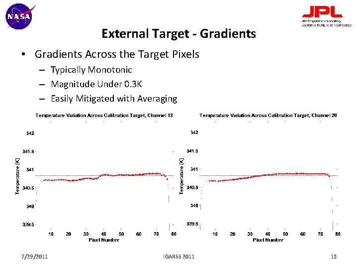
External Target - Gradients • Gradients Across the Target Pixels – Typically Monotonic – Magnitude Under 0. 3 K – Easily Mitigated with Averaging 7/29/2011 IGARSS 2011 13
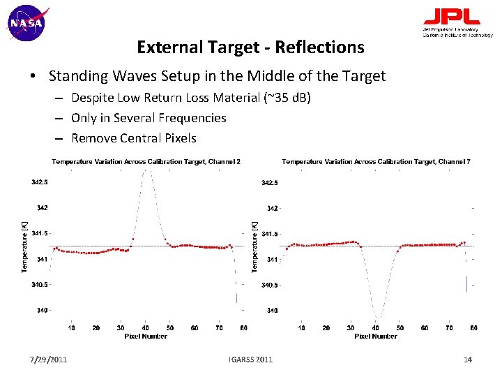
External Target - Reflections • Standing Waves Setup in the Middle of the Target – Despite Low Return Loss Material (~35 d. B) – Only in Several Frequencies – Remove Central Pixels 7/29/2011 IGARSS 2011 14
Initial Processing • Moving Average of the Hot and Ambient Counts – Period of the Heating Oscillation (~110 Seconds) • Time ‘Shift’ in Ambient Counts – Account for linear time drifts • Calculate Per-Scan Gain – Gain = (CHot – CAmb)/(THot – TAmb) [C/K] • Flag Unusable Pixels (-2) – Insufficient Separation of the Hot and Ambient Targets – Differential Temperatures on Targets, 5 x. NEDT – Differential Gain, Threshold (empirical) 7/29/2011 IGARSS 2011 15
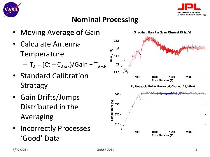
Nominal Processing • Moving Average of Gain • Calculate Antenna Temperature – TA = (Ct – CAmb)/Gain + TAmb • Standard Calibration Stratagy • Gain Drifts/Jumps Distributed in the Averaging • Incorrectly Processes ‘Good’ Data 7/29/2011 IGARSS 2011 16
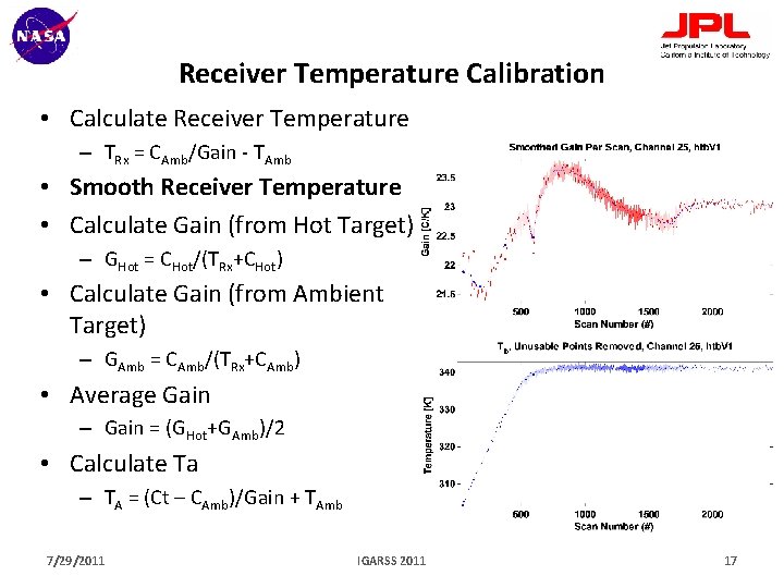
Receiver Temperature Calibration • Calculate Receiver Temperature – TRx = CAmb/Gain - TAmb • Smooth Receiver Temperature • Calculate Gain (from Hot Target) – GHot = CHot/(TRx+CHot) • Calculate Gain (from Ambient Target) – GAmb = CAmb/(TRx+CAmb) • Average Gain – Gain = (GHot+GAmb)/2 • Calculate Ta – TA = (Ct – CAmb)/Gain + TAmb 7/29/2011 IGARSS 2011 17
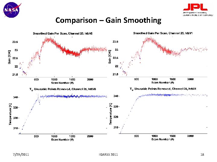
Comparison – Gain Smoothing 7/29/2011 IGARSS 2011 18
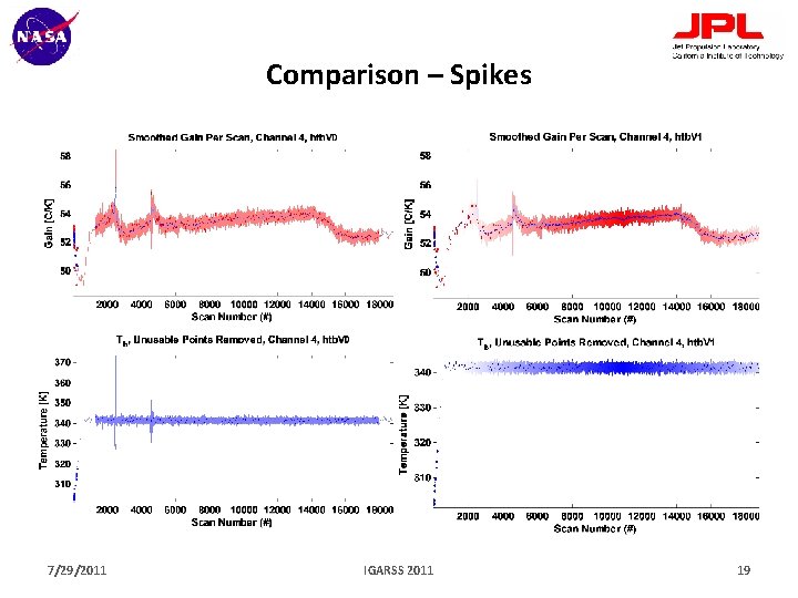
Comparison – Spikes 7/29/2011 IGARSS 2011 19
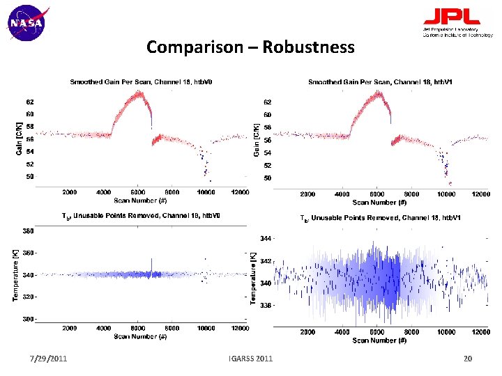
Comparison – Robustness 7/29/2011 IGARSS 2011 20
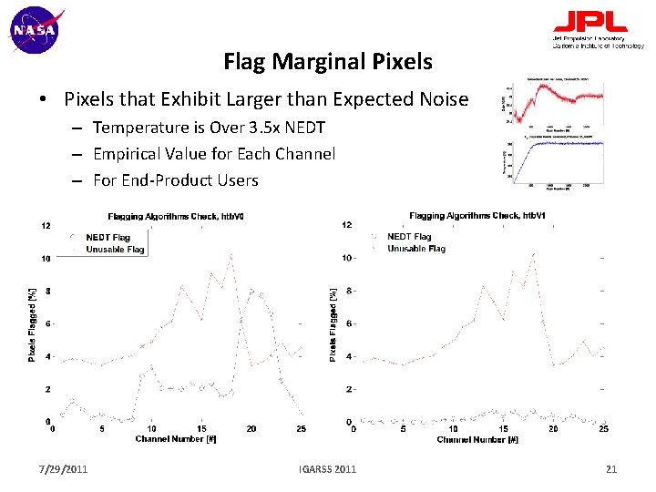
Flag Marginal Pixels • Pixels that Exhibit Larger than Expected Noise – Temperature is Over 3. 5 x NEDT – Empirical Value for Each Channel – For End-Product Users 7/29/2011 IGARSS 2011 21
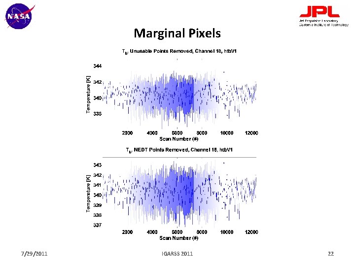
Marginal Pixels 7/29/2011 IGARSS 2011 22
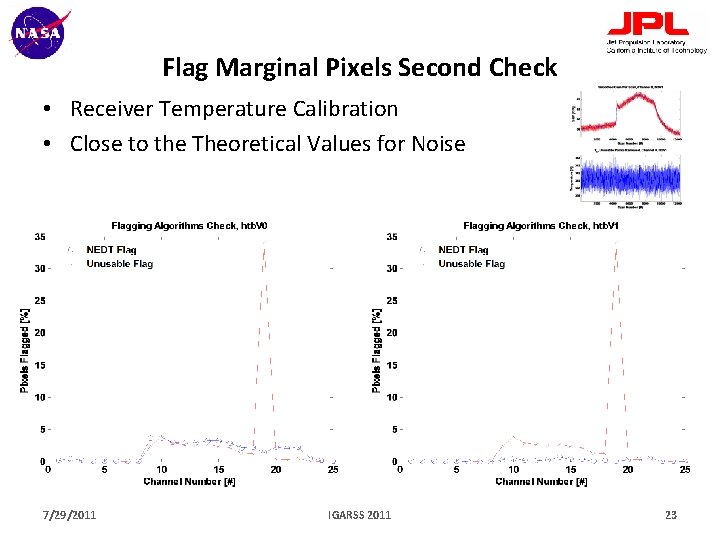
Flag Marginal Pixels Second Check • Receiver Temperature Calibration • Close to the Theoretical Values for Noise 7/29/2011 IGARSS 2011 23
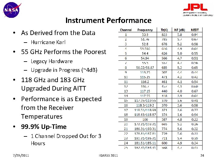
Instrument Performance • As Derived from the Data – Hurricane Karl • 55 GHz Performs the Poorest – Legacy Hardware – Upgrade in Progress (~4 d. B) • 118 GHz and 183 GHz Upgraded During AITT • Performance is as Expected from the Receiver Temperatures • 99. 9% Up-Time – 1 Channel Dropped Out for 3 Hours 7/29/2011 IGARSS 2011 24
Summary • External Targets Well Characterized • HAMSR Successfully Participated in GRIP Campaign – Data System Utilized High Bandwidth Link (‘Real-Time’) – Utility was Immediate in Directing the GH Flight Path • Calibration Methodology Relies on Stability of Receivers – Front End LNAs vs Entire Gain Chain • HAMSR Receivers as a System Perform to Measured Receiver Temperatures • WISPAR Campaign Had Coincident Dropsondes – Absolute Calibration Comparison Pending • Instrument calibration and characterization (Brown et al. , TGRS, in press) 7/29/2011 IGARSS 2011 25
Backup Slides • • HAMSR Timeline HAMSR Block Diagram External Target Construction Pre-Flight Evaluation Allan Variance LN 2 Stare GRIP – Agency Coordination Danielle, Earl and Fiona 7/29/2011 IGARSS 2011 26
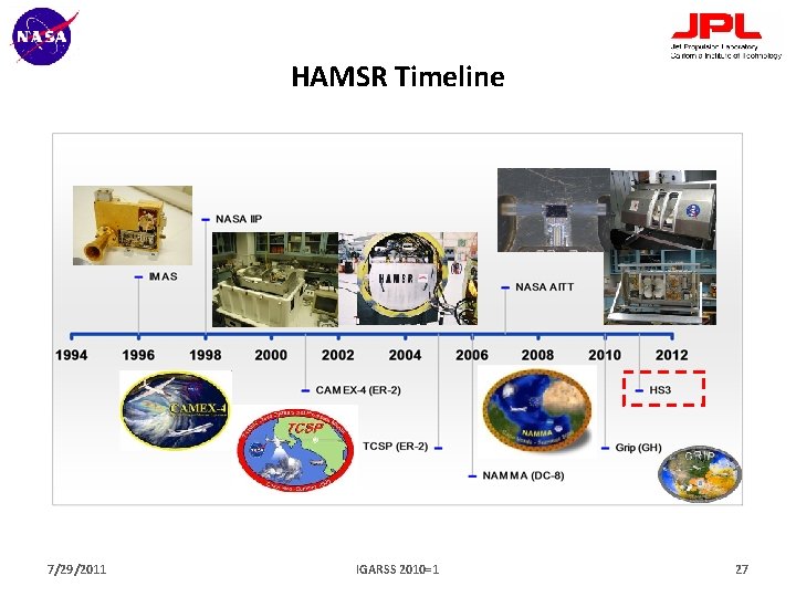
HAMSR Timeline 7/29/2011 IGARSS 2010=1 27
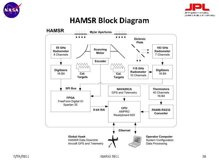
HAMSR Block Diagram 7/29/2011 IGARSS 2011 28

External Target - Construction • Pyramidal Blackbody Calibration Targets – Ambient and ~680 C • Commercial Product with -50 d. B Return Loss Spec – Heavy Aluminium Coated with a Ferrite Loaded Epoxy Absorbing Material – 16 x 12 cm Area, 4 cm Long Pyramids, 1 cm Apart at Tips • 4 Thermistors Embedded in Targets at the Tips • Insulated in Styrofoam – ~35 d. B Return Loss 7/29/2011 IGARSS 2011 29
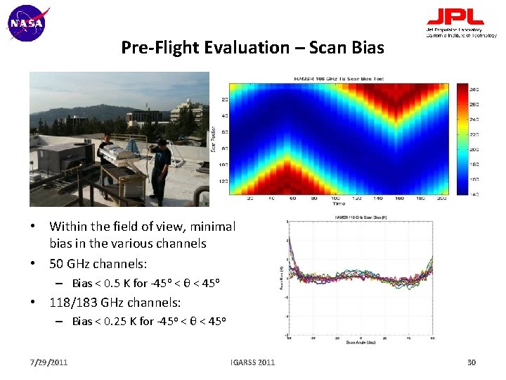
Pre-Flight Evaluation – Scan Bias • Within the field of view, minimal bias in the various channels • 50 GHz channels: – Bias < 0. 5 K for -45 o < θ < 45 o • 118/183 GHz channels: – Bias < 0. 25 K for -45 o < θ < 45 o 7/29/2011 IGARSS 2011 30
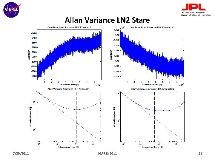
Allan Variance LN 2 Stare 7/29/2011 IGARSS 2011 31
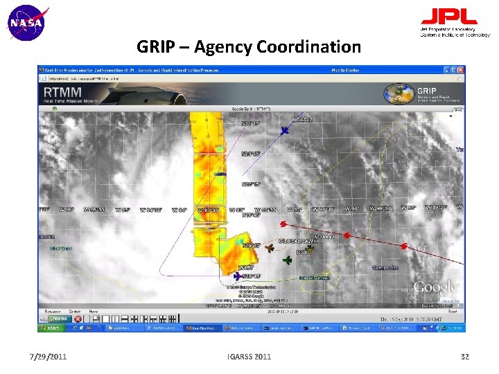
GRIP – Agency Coordination 7/29/2011 IGARSS 2011 32

Danielle, Earl and Fiona 7/29/2011 IGARSS 2011 33
- Slides: 33