Calibrating Transmitters Paul Wakeham Learning Objectives Demonstrate converting

Calibrating Transmitters Paul Wakeham

Learning Objectives • Demonstrate converting transmitter input signals to output signals • Follow lab procedure without guidance to perform transmitter calibration • Document transmitter nameplate data

Operation % INPUT = % OUTPUT i. e: When input is 75%, Output is 75% INPUT TRANSMITTER OUTPUT

Conversion Formula Range: Always Two values; URV: Upper Range Value LRV: Lower Range Value: 4– 20 ma , URV = 20, LRV= 4 Span = 16, URV–LRV (20 – 4)

Conversion Formula Output = % Span x Span + LRV If input is at 75% of Span Than; Output =. 75 x (20 – 4) + 4 Output = 8 milliamp

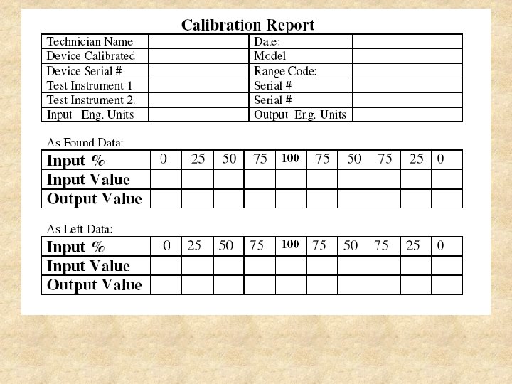
Transmitter Documentation

Transmitter Documentation Model and Serial Number Rosemount 1151 - SDP-URD 476

Transmitter Documentation Model and Serial Number Rosemount 1151 - SDP-URD 476 Range Code Range 4: 150 in. H 2 O

Transmitter Documentation Model and Serial Number Rosemount 1151 - SDP-URD 476 Range Code Range 4: 150 in H 2 O Maximum Working Pressure MWP: 2000 PSI

Example Current Loop Sensor Input • Pressure 2200 ºC ZERO SPAN + – 24 V Loop Supply 4 – 20 ma 2 Wire Transmitter With permission from Fluke Education Partnership Program

Calibration Diagram Manometer 0 – 5 Volt 250 ohm D/P Cell ma + 24 volt DC Pump H L Vent

Calibrating D/P Cell Video • To view the video, click the You. Tube link below: http: //www. youtube. com/watch? v=Ceg 24 baac. PA

Calibration Summary • • • % Input = % Output = % Span x Span + LRV Document All Data Calibrate to Percent of Error Output must be Linier
- Slides: 14