CAD CAM IN RESTORATIVE DENTISTRY PRESENTED BY SYED

CAD- CAM IN RESTORATIVE DENTISTRY PRESENTED BY: SYED MUKHTAR-UN- NISAR ANDRABI ASSISTANT PROFESSOR CONSERVATIVE DENTISTRY & ENDODONTICS

Introduction CAD/CAM is an acronym for computer-aided design/computer-aided manufacturing. With CAD/CAM, parts and components can be designed and machined with precision using a computer with integrated software linked to a milling device. CAD/CAM technology was introduced to dentistry in 1988 in Germany and is widely used today to generate tooth-colored fillings (Machined Restorations) that are bonded to front and back teeth. CAD/CAM can be used for making fillings chairside in the dental office or fabricating restorations in a dental laboratory.
 The science of CAD/CAM dentistry has expanded rapidly in the last")
Introduction (contd. ) The science of CAD/CAM dentistry has expanded rapidly in the last few years. The types of restorations possible using such systems are almost as varied as the dentists who embrace them. The chairside CAD/CAM system is approaching 20 years of clinical experience and has a proven track record on all relevant aspects of clinical performance, including fit, longevity and survival rates, sensitivity, strength, and wear.
 copy milling and")
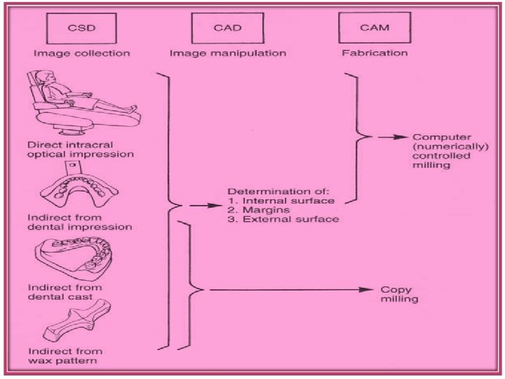
The two principal machining approaches for dental restorations are: (1) copy milling and (2) CAD/CAM milling.

Copy Milling Copy milling uses a replica (e. g. , wax, plastic, stone, or metal) of the desired form as a guide for a milling machine. The surface of the replica is traced by turning the pattern and touching the patterns surface with a finger stylus. The positions of the pattern and stylus are used to adjust the positions of a block of machinable material and a milling tool cutting the block, respectively.

CAD-CAM Milling CAD/CAM milling uses digital information about the tooth preparation (computerized surface digitization [CSD]), or a pattern of the restoration to provide a computeraided design (CAD) on the video monitor for inspection and modification. Once threedimensional image for the restoration design is accepted, the computer translates the image into a set of instructions to guide a milling tool (computerassisted manufacturing [CAM]) in cutting the restoration from a block of material.

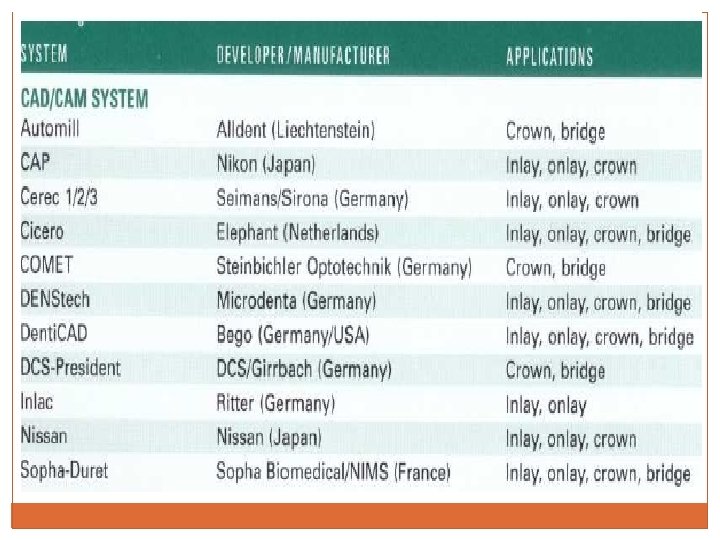
History The earliest attempt to apply CAD/CAM technology to dentistry began in the 1970 s with Ø Bruce Altschuler, in the United States, Ø Francois Duret, in France, and Ø Werner Mormann, and Marco Brandestini in Switzerland. q Duret developed the Duret system, which was later marketed as the Sopha Bioconcept system demonstrating the ability of CAD/CAM to generate single-unit, full-coverage restorations. However, this system was not successful in the dental market because of its complexity and cost. q Mormann and B r a n d e s t i n i : first commercially available dental CAD/CAM system was CEREC (Sirona Dental Systems)

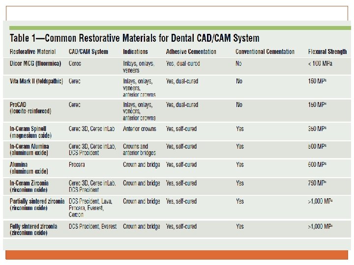
History Today’s CAD/CAM systems – both chair-side and laboratory-based– are being used to design and manufacture metal, alumina, and zirconia frameworks, as well as all-ceramic and composite for: Ø crowns, inlays, and veneers that may be stronger, fit better, and are more esthetic than restorations fabricated using traditional methods.

Procedure When creating a chairside CAD/CAM filling, the dentist Makes a digital picture of the prepared tooth containing three-dimensional information about the size of the tooth and defect being restored, as well as the adjacent teeth. (digital impression) Designs the desired filling directly on a computer screen using CAD/CAM software. (CAD) A tooth-colored block of ceramic or composite material is machined by fine diamond drills to produce the designed filling. (CAM) The CAD/CAM filling is then tried in the mouth, adjusted, polished, and bonded in place with a composite resin bonding cement.

Digital Impression Or Data Capture Data capture differs remarkably between commercially available dental CAD/CAM systems. Ø Intraoral digital 3 -D scanning device (digitizer): directly scans tooth preparations intra-orally. Integral component of some CAD-CAM devices such as CEREC-3 D & Evolution 4 D. Works in combination with dedicated CAD software. Disadvantage : exceptionally sensitive to any motion. Slight movement of a patient during data acquisition would compromise the quality of the data, ultimately leading to a restoration that would not fit. Ø Extra-oral digitizers: capture data from models
 Several CAD software programs are available commercially for designing virtual 3")
Restoration Design (CAD) Several CAD software programs are available commercially for designing virtual 3 -D dental restorations on a computer screen. The software programs usually are proprietary to the CAD/CAM system and cannot be interchanged among systems. Operator has the option to modify the automatically designed restoration to fit his or her preferences. When the design of the restoration is complete, the CAD software transforms the virtual model into a specific set of commands.
 CAM uses computer-generated paths to shape a part. Early systems relied")
Restoration Fabrication (CAM) CAM uses computer-generated paths to shape a part. Early systems relied almost exclusively on cutting the restoration from a prefabricated block with the use of burs, diamonds or diamond “subtractive method”. “additive” CAM approaches (also called “solid free-form fabrication”), instead of cutting, the system sinters material along the design path created, building a part from a “bath” of ceramic or metal powder and adding material continually until the complex part is complete. No excess material remains. Selective Laser sintering technology

BONDING of CAD-CAM Bonding of ceramic CAD/CAM restoration is a critical step in achieving good long-term results: (1) etching enamel to increase the bondable surface area; (2) etching, priming, and applying the bonding agent to dentin (when appropriate); (3) etching (by HF acid) and then priming (silanating) the restoration; and (4) cementing the restoration with composite cement.

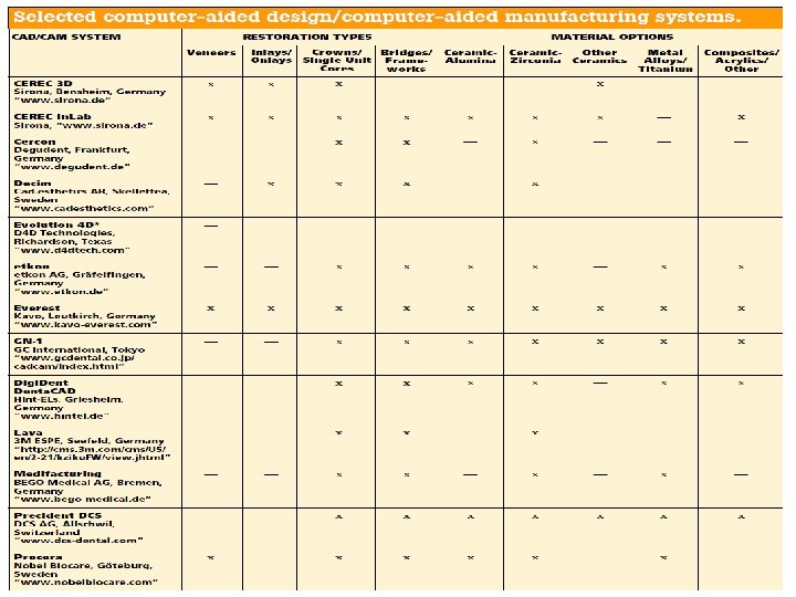
Common CAD/CAM Systems CAD/CAM systems may be categorized as In-office Or Laboratory Systems Among all dental CAD/CAM systems, CEREC is the only manufacturer that provides both in-office and laboratory modalities. Similar to CEREC is the Evolution D 4 D Laboratory CAD/CAM systems include: DCS Precident, Procera, CEREC in. Lab, and Lava. Evolution D 4 D Everest Cercon is a laboratory system that possesses only CAM capabilities without the design stage.

CEREC SYSTEM CEREC -1, CEREC- 2, CEREC- 3 D, CEREC in. Lab With CEREC 1 and CEREC 2, an optical scan of the prepared tooth is made with a couple charged device (CCD) camera, and a 3 -dimensional digital image is generated on the monitor. The restoration is then designed and milled. With the newer CEREC 3 D, the operator records multiple images within seconds, enabling clinicians to prepare multiple teeth in the same quadrant and create a virtual cast for the entire quadrant.

CEREC SYSTEM CEREC in. Lab is a laboratory system in which working dies are laser-scanned and a digital image of the virtual model is displayed on a laptop screen. After designing the coping or framework, the laboratory technician inserts the appropriate VITA In-Ceram block into the CEREC in. Lab machine for milling. The technician then verifies the fit of the milled coping or framework. The coping or framework is glass infiltrated and veneering porcelain is added.

CEREC SYSTEM In vitro evaluation of CAD/CAM ceramic crowns that compared the marginal adaptation of CEREC 2 with CEREC 3 D concluded that crown adaptation for CEREC 3 D (47. 5 ± 19. 5 μm) was significantly better compared with CEREC 2 (97. 0 ± 33. 8 μm). (Ellingsen LA, Fasbinder DJ. In vitro evaluation of CAD/CAM ceramic crowns [abstract 2640]. J Dent Res. 2002; 81: 331)

DCS Precident The DCS Precident system is comprised of a Preciscan laser scanner and Precimill CAM multitool milling center. The DCS Dentform software automatically suggests connector sizes and pontic forms for bridges. It can scan 14 dies simultaneously and mill up to 30 framework units in 1 fully automated operation. Materials used with DCS include porcelain, glass ceramic, In-Ceram, dense zirconia, metals, and fiberreinforced composites. This system is one of the few CAD/CAM systems that can mill titanium and fully dense sintered zirconia.

Procera/All. Ceram was introduced in 1994 Generates alumina and zirconia copings. First master die is scanned and then an enlarged virtual die is made to meet the sintering shrinkage of the porcelain. Sintering at 2, 000°C imparts maximum density and strength to the milled copings. The complete procedure for Procera coping fabrication is very technique-sensitive because the degree of die enlargement must precisely match the shrinkage produced by sintering the alumina or zirconia.

LAVA § Introduced in 2002, Lava uses a laser optical system to § § digitize information from multiple abutment margins and the edentulous ridge. The Lava CAD software automatically finds the margin and suggests a pontic. The framework is designed to be 20% larger to compensate for sintering shrinkage. The computer- controlled precision milling unit can mill out 21 copings or bridge frameworks without supervision or manual intervention. Milled frameworks then undergo sintering to attain their final dimensions, density, and strength

Everest Marketed in 2002, the Everest system consists of scan, engine, and therm components. Its machining unit has 5 -axis movement that is capable of producing detailed morphology and precise margins from a variety of materials including leucite-reinforced glass ceramics, partially and fully sintered zirconia, and titanium. Partially sintered zirconia frameworks require additional heat processing in its furnace.

CERCON Ø The Cercon System is commonly referred to as a CAM system because it does not have a CAD component. Ø In this system, a wax pattern (coping and pontic) with a minimum thickness of 0. 4 mm is made. Ø The system scans the wax pattern and mills a zirconia bridge coping from presintered zirconia blanks. Ø The coping is then sintered in the Cercon heat furnace (1, 350ºC) for 6 to 8 hours. Ø A low-fusing, leucite-free Cercon Ceram S veneering porcelain is used to provide the esthetic contour.

Marginal Integrity of CAD/CAM Restorations One of the most important criteria in evaluating fixed restorations is marginal integrity. Evaluating inlay restorations, Leinfelder and colleagues reported that marginal discrepancies larger than 100 μm resulted in extensive loss of the luting agent. Christensen suggested a clinical goal of 25 μm to 40 μm for the marginal adaptation of cemented restorations. Most clinicians agree that the marginal gap should be no greater than 50 μm to 100 μm Current research data indicate that most dental CAD/CAM systems are now able to produce restorations with acceptable marginal adaptation of less than 100 μm

Clinical Considerations ADVANTAGES DISADVANTAGES Excellent flexural Inability to produce strength Ability to rigidly bond to the remaining tooth structure Repairable if damaged excellent estheticsthey are monolithic i. e restn is milled from a block of single shade. Technique sensitivity High cost of the equipment

CONCLUSION CAD/CAM systems have dramatically enhanced dentistry by providing high-quality restorations. The evolution of current systems and the introduction of new systems demonstrate increasing user friendliness, expanded capabilities, and improved quality, and range in complexity and application. New materials also are more esthetic, wear more nearly like enamel, and are strong enough for full crowns and bridges.

Thank you
- Slides: 30