Bus Rapid Transit Infrastructure Design Roadway and Junctions

Bus Rapid Transit Infrastructure Design Roadway and Junctions Bus stops Shreya Gadepalli Senior Program Director Institute for transportation and Development Policy

Roadway and Junction Design
")
Intersections are critical SO REDUCE CONFLICTS Restrict turning options where possible (no right turns) Avoid elements which can be put elsewhere (No parking near intersection + Shift back BRT stations) Provide time for pedestrians to cross and safe places to wait

INTERSECTION CAPACITY varies with signal phasing
 All turning movements possible in two")
TWO PHASE OPTIONS Signalized Round about (square geometry) All turning movements possible in two signal phases Higher junction capacity Lower time lost for BRT as well as mixed traffic
 Size based on turning movement volume")
TWO PHASE OPTIONS Signalized Round about (square geometry) Size based on turning movement volume Signal cycle an essential component of geometric design Short signal cycle essential avoid jam Short signal cycle gives frequent pedestrian crossing time
 Two Phase signal phase Higher junction")
TWO PHASE OPTIONS Signalized round about (Split intersection) Two Phase signal phase Higher junction capacity Multiple arms incorporated

TWO PHASE OPTIONS Only straight movement allowed at junction with two phase signals Right turning movement through U-turn - Left turn combination

BUS STATION LOCATION Pedestrian behavior at junction Bus blocks bus bay due during Red Phase not letting buses behind to access the bus stop Risky behavior of Pedestrians to access the bus station Pedestrian has to get across MV traffic of multiple directions in unsafe conditions BUS STOP Fewer lanes for MV traffic at junction results in longer cycle time and lower junction capacity

BUS STATION LOCATION Fewer lanes to cross to reach BRT station Median Station allows for easy transfers BRT STOP AWAY AT FROM Synchronized signals for INTERSECTION safe pedestrian crossing More space for mixed traffic at intersection JUNCTION DESIGN

BUS STATION LOCATION If BRT Station is at the Junction then Many buses cannot utilize GREEN signal since earlier bus blocks the bus bay because it is waiting at the RED signal Results in Long queues and bunching of buses and slows down the BRT system May result in unwanted pedestrian behavior wishing to reach bus stop

BUS STATION LOCATION Station setback from Intersection Station at Intersection

BRT Stations

BUS STATION SATURATION Speed vs saturation B Rapid T B Slow T 35 30 speed (km/h) 25 20 cars 15 buses 10 5 0 0 0. 1 0. 2 0. 3 0. 4 0. 5 0. 6 saturation 0. 7 0. 8 0. 9 1

BUS STATION CAPACITY Increase in capacity with overtaking lane Large bus flows with inadequate infrastructure causes huge bunching Multiple bus bays with overtaking lane for entry exit as well as express services reduces bus stop saturation and increases system capacity

LANES AT BUS STATIONS Lane width requirement Open bus platforms do not regulate where buses stop. This creates confusion at the station Narrow overtaking lane obstructs oncoming buses and mixed traffic lanes – minimum width at bus station location with overtaking lane > 7 m

Platform not properly aligned and only one door per bus at each station. Undersized stations for actual demand This caused crowing at inside stations

BUS STATION CAPACITY Station dwell time and capacity Bus queuing even at very low capacity (3000 pphpd) Higher demand exists on the corridor so other buses ply in mixed traffic

BUS STATION SIZE Waiting space inside bus station One size does NOT fit all Estimating passenger boarding and alighting demand of each bus stop location is important for bus station sizing. Small and Narrow station Creates large passenger queues outside the bus station Results in discomfort and reduced efficiency of boarding

BUS STATION PLATFORM What it should be What it should NOT be At level boarding Maximum gap of 10 cm between bus floor and Platform

BUS STATION FEATURES System Identity and Station Name High ceiling with partial roof cover Bus Route information Safe distance between Bus and BRT station (250 mm) Platform extension for close docking of bus (<125 mm)

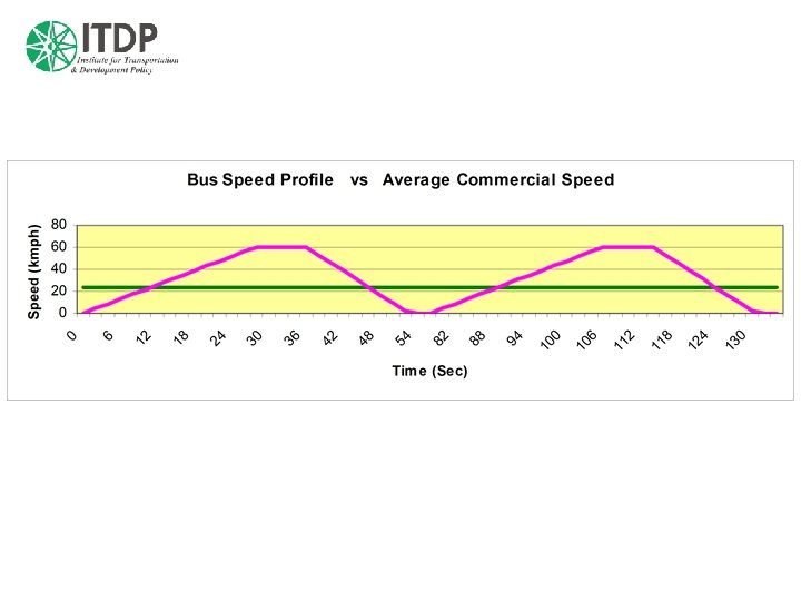
DOES SPEED MATTER? • Most mass transit options can have relatively similar operating speed, other aspects remaining similar • Speed is important since the fleet size required becomes lower for the same frequency of service • Average speed increases as distance between stops increases. But speed of system matters only so far as total trip time of passengers is reduced

Stop spacing and Passenger trip time • When trip lengths are short, closely placed stations are preferable since slow speed walk time becomes a large component of total trip time. • As trip lengths increase, system speed can be increased by increasing station spacing

BRT and Pedestrian

PEDESTRIAN CROSSING every 120 -200 m else they will make their own crossing! Pedestrian Delay Over 30 sec – Risky Behavior Over 60 sec – would surely attempt to cross Very long signal cycles with long waiting time for pedestrians makes them take chances and meet with accident. Lower pedestrian delay requires shorter signal cycles

Zebra crossing Median treatment Which one is better? The Answer is evident

At grade access to bus stops

HCBS Junction Conceptual Design Waiting space for NMV in front of MV Larger Pedestrian crossing space No free left turns

Speed vs Injury

Pedestrian Safety 5% Speed drop results in Removing free left turns will reduce 15% fewer collisions 10% fewer pedestrian fatalities 20% less severe pedestrian injuries Left turn crashes by 19 % Collisions with pedestrians by 38% Collisions with cyclists by 50% Speed Drop Collision Drop 2 km/h 5% 5 km/h 15% 10 km/h 42%

Left turning speed and turning radius Target turning speed Trucks < 10 km/h Cars < 20 km/h Effective Turning Radius Use 4. 5 m compound curve NOT 15 m simple curve which results in 30 -35 km/h for cars)

Left turn slip lane design High Vehicle speed but low visibility of Pedestrian Unsafe Lower Vehicle speed with better visibility of Pedestrian Safe

Slip lanes What they should NOT be

UNUSED but UNSAFE Observing existing road use can teach us a few things about safe and realistic geometry

Something to think about Reality Fantasy Eliminate or reduce severity of crashes Make drivers and pedestrians behave Minimize pollution and noise Develop a cleaner and quieter engine Recapture urban space for people Effectively utilize existing infrastructure Design city so everyone drives everywhere all the time Build more capacity to move out of congestion

3 Principals to remember Vehicle speed Speed is a significant determinant of severity of crashes, should be logical with respect to context, and is a critical factor in safety where there are conflicting traffic modes. Lower vehicle speeds open a range of design options that enable a street to look less like an expressway and more like a neighborhood street. Pedestrian and bicycle exposure risk By making the distance to cross the street shorter, the time spent crossing the street is reduced and the exposure risk is subsequently reduced. Driver predictability If other street users can better predict how and where a particular vehicle will be driven, the street will be safer.
- Slides: 37