BUS DUCT DESIGN PART 2 Reminder Assignment LAB
")
BUS DUCT DESIGN : PART 2 Reminder • Assignment • LAB 3 (auto. CAD)

LAB Overview
")
Design Method 1. Fault Current 2. Temperature Rise 3. Total Connected Load (TCL)

Fault Current . The enclosure of the bus system provides the cooling surface for heat dissipation. The ratio of the area of the current-carrying conductors to the area of the enclosure will provide the basis to determine the heat dissipation effect. . Dissipation factors that can be considered as likely derating for a bus system under different conditions

Fault Current Material Size in mm Area Weight/ sqmm km 12 X 2 15 X 3 20 X 2 20 X 3 20 X 5 25 X 3 25 X 5 30 X 3 30 X 5 40 X 3 40 X 5 40 X 10 50 X 5 50 X 10 60 X 5 60 X 10 80 X 5 80 X 10 100 X 5 100 X 10 120 X 10 160 X 10 200 X 10 24 30 75 40 60 100 75 125 90 150 120 200 400 250 500 300 600 400 800 500 1000 1200 1600 2000 0. 209 0. 262 0. 396 0. 351 0. 529 0. 882 0. 663 1. 11 0. 796 1. 33 1. 06 1. 77 3. 55 2. 22 4. 44 2. 66 5. 33 3. 55 7. 11 4. 44 8. 89 10. 7 14. 2 17. 8 Fault level (KA) Withstand time Aluminium 35 50 65 1 sec. 443 633 823 Copper 35 50 65 285 407 528 current carrying capacity in amp ( copper ) at 35 deg. C AC ( no. of bus) DC ( no. of bus) I II III II II 110 200 115 205 140 200 145 245 170 300 175 305 185 315 190 325 220 380 225 390 295 500 300 510 270 460 275 470 350 600 355 610 315 540 320 560 400 700 410 720 420 710 430 740 520 900 530 930 760 1350 1850 2500 770 1400 2000 630 1100 1650 2100 650 1150 1750 920 1600 2250 3000 960 1700 2500 760 1250 1760 2400 780 1300 1900 2500 1060 1900 2600 3500 1100 2000 2800 3600 970 1700 2300 3000 1800 2500 3200 1380 2300 3100 4200 1450 2600 3700 4800 1200 2050 2850 3500 1250 2250 3150 4050 1700 2800 3650 5000 1800 3200 4500 5800 2000 3100 4100 5700 2150 3700 5200 6700 2500 3900 5300 7300 2800 4800 6900 9000 3000 4750 6350 8800 3400 6000 8500 1000 0 200 msec. 198 283 368 40 ms. 89 127 165 10 ms. 44 63 82 127 182 236 57 81 106 28 41 53

Fault Current. Example : A bus duct provide a means for carrying high current. It provide high system reliability. Assuming a hospital with rating current 2000 A needs to be installed with a copper bus duct. By assuming the nominal voltage supply is 415 V, 50 Hz, and fault level 35 k. A for 1 sec. Refer Table.

Temperature Rise • During the short circuiting, the bus bar should be able to withstand thermal as well as mechanical stress. • When a short circuiting takes place, the temperature rise is directly proportional to the square of the rms value of the fault current. • The duration of short circuiting is very small i. e. one second till the breakers opens and clears the fault. • The heat dissipation through convection and radiation during this short duration is negligible and all the heat is observed by the busbar itself. • The temperature rise due to the fault can be calculated by applying the formula.

Temperature Rise

Temperature Rise. Example : Determine the minimum conductor size for a fault level of 50 k. A for 1 second for an aluminum conductor. Assuming the temperature rise to be 100 degree celcius and the initial temperature of the conductor at the instant of the fault 85 degree celcius then.

TCL

TCL Example : A building with 800 A load current need to be installed with copper bus duct. Find the size of bus duct. Refer Table.
=Total Connected Load, (TCL)")
TCL • if Ib no given. . • ib (three phase)=Total Connected Load, (TCL) / 610. 9 • ib (single phase)= Total Connected Load, (TCL) / 240

TCL Example : LECTUREEXAMPLE BUS BAR DESIGN. docx

Other Design Consideration 1. Size of enclosure 2. Voltage Drop 3. Skin Effect

Size of Enclosure. The enclosure of the bus system provides the cooling surface for heat dissipation. The ratio of the area of the current-carrying conductors to the area of the enclosure will provide the basis to determine the heat dissipation effect. . Dissipation factors that can be considered as likely derating for a bus system under different conditions

Voltage Drop • The voltage drop across a bus system should be as low as possible and generally within 1– 2% of the rated voltage. • This criterion will generally be applicable to a high current LV system. • affect the stability of the system as well as the performance of the connected load.
 = √(3 ) x Ib x ( R cos")
VD BUSBAR Voltage drop (Vd) = √(3 ) x Ib x ( R cos θ+X sin θ) where; Ib = Current design R & X = impedance in mikro Ohm from Table voltage drop Busduct θ = refer to pf value (0. 85) Allowable voltage drop for bus duct is only 1 -2% from supply voltage
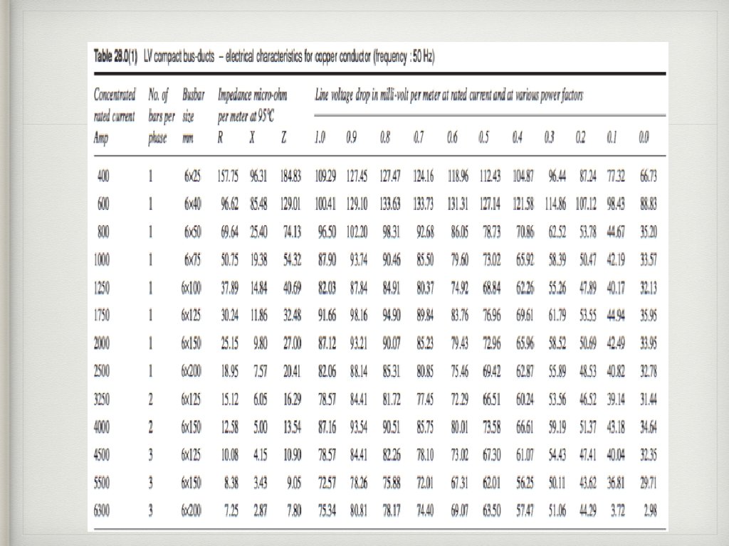

example- try • given current design is 1000 A, find suitable size of copper bus duct and determine the voltage drop either meet the requirement or not. • Busduct size = Ib/1. 5 mm • Voltage drop (Vd) = √(3 ) x Ib x ( R cos θ+X sin θ) • answer=?

END of Chapter 4 Thank You
- Slides: 21