BURIED FLEXIBLE PIPELINES The Design Process Boundary Conditions

BURIED FLEXIBLE PIPELINES The Design Process- Boundary Conditions Design Fundamentals-AS 2566. 1 Materials Installation AS 2566. 2 Tips, Tricks & Traps Presented by Geoffrey D Stone C. Eng FIMech. E; CP Eng FIEAust RPEQ Principal Blenray Pty Ltd ( Design Detail & Development) geoffrey. stone@yahoo. co. uk 0402 35 2313

THE DESIGN PROCESS Boundary Conditions Soils & Soil Data Trench Width & Depth Structural Response to Loading Trench Details Stiffness Thrust Blocks Structural Interfaces Water Table Design Loads Trench & Embankment Fill Superimposed Live Loads Other Superimposed Loads

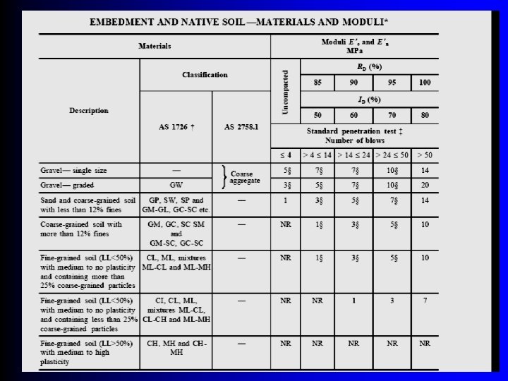
Soils & Soils Data Native Soil – Classify – Modulus Bedding – Type Embedment – – Material Compaction Geo-textile Water Table Backfill – Type – Compaction Piles Testing – Field – Laboratory

Trench Width & Depth AS 2566. 1 Minimum Embedment or Embankment Shape of trench

Trench Dimensions

Structural Response to Loading

Stiffness AS 2566. 1 2 year values of pipe stiffness suitable for good soils 50 year values of pipe stiffness should be used for poor soils, uncontrolled installations or other higher risk applications

Stiffness AS 2566. 1

Thrust Blocks Not required for fully welded systems as in ABS, PP, PVC-U, PB or PE Required for rubber ring systems as used for DICL, MSCL, GRP & PVC-U/O/M Design basis – Steady state pressure – Unsteady state pressure spikes – Hydrostatic test pressure

Structures Interfaces Differential Settlement Soil swelling Water Retaining Shear Loading Thermal Loading Chaffing Water seal in concrete

Water Table Water hydrostatic level applies load onto pipe-refer AS 2566 Rising water applies uneven load onto pipe and the pipe may buckle or exceed its strain limit Water may cause flotation of empty pipe and special embedment may be necessary High water table increases construction difficulty – Safety – Dewatering – Quality

Loading Design loads due to trench & embankment fill External hydrostatic loads Internal pressure Superimposed dead loads Superimposed live loads Other unsustained loads

Design Loads due to Trench & Embankment Fill

Superimposed Live Loads

Superimposed Live Loads

Other Unsustained Loads 1. 2. 3. 4. Specialist Engineering National Codes Local Conditions Risk Likelihood Consequences Responsibility Safeguarding Earthquake Vibration/Shock Differential Settlement Thermal Strain Subsidence Airport runways Railways

DESIGN FUNDAMENTALS AS 2566. 1 Buried Flexible Pipelines-Design Deflection Strength Internal Pressure Combined Loading Buckling Hoop Stress Ring Bending Strain Creep Temperature Other Considerations

Deflection Short term Long term Vertical & Horizontal – Considered equal – Effect of excess side compaction Modulus to use Acceptance criteria Measurement during installation

Strength Loads cause strain in pipe wall Ring compression strains << ring bending strains AS 2566. 1 predicts maximum tensile ring bending strains A Shape Factor adjusts strain values – True Ellipse Shape Factor Df=3. 0 – Δhorizontal < Δvertical Shape Factor Df > 3. 0

Internal Pressure Steady State Unsteady State – AS 2566. 1 Requirements 1. 25 – AS 2885 Requirement 1. 10 – Other codes requirements

Combined Loading Combined external load and internal pressure Re rounding effect

Buckling Ovalization Buckling External Pressure No substantial soil support-Timoshenko Substantial soil support –I. D. Moore

Hoop Stress in the wall due to pressure Only criteria used for pipe class selection Does not take into account other stresses Basis of the Pipe Class System Relaxes with time for thermoplastic pipes Never Constant

Ring Bending Strain Importance of Strain Comparison of allowable strain in materials 1. ABS 1% 2. GRP 0. 18 to 0. 6 % 3. PE 4. 0% 4. PVC-U 1% 5. PVC-M 1% 6. PVC-O 1. 3%

Creep Variation of Properties in Time Long term loading/Stress relaxation Reverse loading/Stress magnitude Repetitive loading/Fatigue

Temperature The design temperature may vary due to: • Ambient diurnal temperature variations • Flow rate • Fluid temperature range • Process conditions • Installation ambient temperature • Wall thickness

Other Considerations Anchor forces Differential Settlement Earthquake Subsidence Testing conditions Corrosion Mass of pipe contents Thermal Strain Local buckling Fatigue Pavement settlement

Materials Selection Types Costs Class Characteristics Fittings & Valves Modulus GRP Modulus Thermoplastic Pipes

Materials - Types GRP ABS PE PVC-U, PVC-M, PVC-O DICL MSCL

Materials Selection Costs – Supply 1. Safety 2. Availability 3. Maintenance 4. Energy 5. Risks 1. Pipe 2. Fittings 3. Supports Costs – Installation 1. 2. 3. 4. 5. Standard of trades Equipment Jointing Access Testing Costs - Whole of Life Costs - Standards 1. Authority 2. Industry 3. Acts

Selection of Pipe Class Design Pressure Steady State Design Pressure Unsteady State Vacuum Conditions Industry Application & Environment Soil/Pipe Structure Design Standardization Risk – Likelihood – Consequences – Responsibility

Typical Material Characteristics

Fittings & Valves Valve classes do not meet all pipe classes Injection moulded fittings- Size Limitation Manufactured fittings -Larger Sizes – Tees – Bends Jointing Gaskets Expansion Bellows Saddles Valves – – Isolation Check Air release Control

Modulus-GRP Pipes Manufacturers establish values by test & calculation Axial & longitudinal modulus differs Values at various temperatures required for design Strain rate changes values Standards such as ISO 14692

Modulus-Thermoplastic Pipes Published figures normally are strain rate at 20ºC Value determined by ASTM test – Standard dog bone test specimen – Fixed strain rate Values at various temperatures required for design Strain rate changes values

INSTALLATION Trench Excavation Trench Shields Laying & Jointing Embedment & Compaction Thrust Blocks Hydrostatic Testing

Trench Excavation Excavator bucket width Excavated depth Soil removal, testing and stockpile Shape of trench Pockets for pipeline projections Thrust block preparation Dewatering Welding machine access Adjacent pipes

Trench Shields When to use Remove in stages Affect on compaction Geotextile fabric Over excavation Wide trench

Trench Shields

Laying and Jointing Join on the bank and lay Lay in trench and join Rubber ring joints PVCU, PVC-M, PVC-O, GRP, DICL & MSCL Solvent welded joints. ABS, PVC-U & PVC-M Fusion butt weld-PE, PB & PP Electro-fusion couplings -PE Wrapped joints-GRP Welded joints-steel Flanges & Mechanical Joints-All Alignment & Bending Adjacent parallel pipes Crossing Pipelines Removal of temporary pegs and supports

Embedment & Compaction Materials Dewatering Bedding Side Support Overlay Migration of fines Pipeline Protection Prevention of floatation Compaction trials Compaction controls Deflection controls Gauging

Thrust Blocks

Hydro-testing Establish test pressure Test standard Prepare test equipment Prepare ITP’s Prepare test points Source of test water Disposal of test water Selection of test lengths Owner’s witness Records
 – DICL, MSCL, GRP & PVC")
Hydrotest Methods Constant pressure test (No water loss) – DICL, MSCL, GRP & PVC Constant pressure test (water loss) – PE, ABS, PP & PB Pressure decay – PE & PB Pressure rebound- DN ≤ DN 315 ABS, PB & PE

Tips, Tricks & Traps Design Installation Testing Product quality Completion In Service leaks

Tips, Tricks & Traps - Design pressure may not include surge Temperature profile not defined Pipeline route/soils not adequately surveyed Consultant expects sub contractor or material supplier to do the detail design Lower pipe class than necessary specified Temporary facilities not designed

Tips, Tricks & Traps - Installation Variations from design not engineered Surfaces not cleaned Aged solvent cement Pipe ends bevelled Damaged pipe UV degradation Physical damage Solvent damage to internal surface Use of incorrect solvent Incorrect slings Foreign matter not removed from trench

Tips, Tricks & Traps - Installation No detail drawings Insufficient joints for erection Incomplete insertion in joints Inadequate time for welds or lay ups Differential settlement Resources Poor trench conditions Poor native soil Soil properties not measured routinely Inadequate access Water ingress Cleanliness

Tips, Tricks & Traps -Testing Lack of planning & procedure Standard provisions not understood Inexperienced testers Test pressure unknown Equipment not isolated Procedure not agreed beforehand Records of test not prepared Person to witness test not available Resources not available – – – Water supply Pump Gauges Data logger Temperature instrument Trained personnel

Tips, Tricks & Traps - Product Quality – Inspection or QA Non conformance with drawings Pipe ovality Lining thickness Socket dimensions Surface defects Fabricated fittings – Cracks at weld – Dimensions – Orientation

Tips, Tricks & Traps -Completion Resources & budget Site clean up Reinstatement Handover to owner Records Work as Executed Drawings Quality Assurance Sign-Off Certificate of Practical Completion

Tips, Tricks & Traps - In Service Leaks & Failures Pipe burst Flanged joints leak Solvent welds leak Rubber ring joints leak Fusion welds leak Fittings Buckling of thin wall pipe Thrust blocks Waterhammer Over pressure Pipe shear Fatigue & vibration

Questions 1. 2. 3. 4. Is AS 2566 mandatory? Can AWWA M 45 be used? Is FEA a viable alternative? Who designs pipelines Civil, structural or mechanical engineers?
- Slides: 54