Bunch Length Measurements at the Swiss Light Source
 Linac at the PSI using")
Bunch Length Measurements at the Swiss Light Source (SLS) Linac at the PSI using Electro-Optical Sampling A. Winter, Aachen University and DESY B. Miniworkshop on XFEL Short Bunch Measurement and Timing S. Casalbuoni, T. Korhonen, T. Schilcher, V. Schlott, P. Schmüser, S. Simrock, B. Steffen, D. Sütterlin, M. Tonutti

Overview • motivation • electro-optical sampling • general remarks • experimental setup • results • outlook Axel Winter, 2004

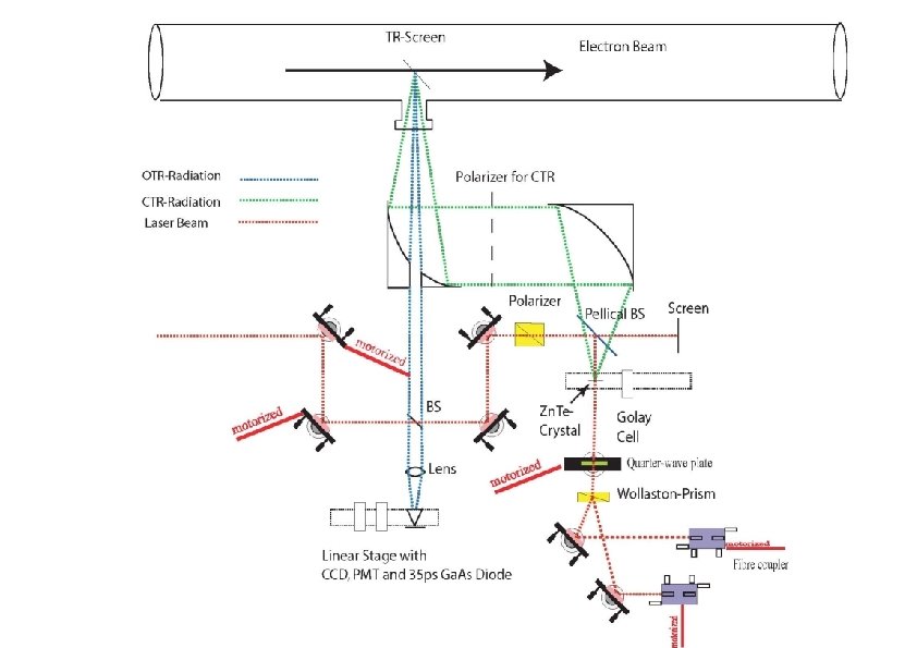
Motivation • Requirements for EOS: • resolution ~ 100 fs • few shot capability • independent of machine settings • nondestructive measurement • feasible solution: detect the change of polarization of a short laser pulse due to birefringence in a Zn. Te crystal induced by the electric field of the electron bunch. • this experiment uses coherent transition radiation (CTR) reflected out of the vacuum chamber onto the crystal Axel Winter, 2004

Overview • motivation • electro-optical sampling • general remarks • experimental setup • results • outlook Axel Winter, 2004
-plane • incident electric vector of")
General Remarks • Zinc-telluride crystal cut parallel to (110)-plane • incident electric vector of CTR and probe laser pulse perpendicular to XYplane • ECTR and ETi. Sa lie in the (110)-plane with angle a with respect to X-axis Axel Winter, 2004

General Remarks II • due to the Pockels effect induced by the CTR, the probe laser pulse will experience a change in polarisation Phase shift: Axel Winter, 2004

Polarization of Laser and CTR • Laser and CTR are horizontally polarized • laser polarisation is slightly elliptical after Zn. Te crystal • elliptical (close to linear) laser polarisation is converted to an elliptical (close to circular) polarisation by quarter wave plate • signal of balanced detector: (remember: G is phaseshift)Axel Winter, 2004

Overview • motivation • electro-optical sampling • general remarks • experimental setup • results • outlook Axel Winter, 2004

The SLS Linac • electron accelerator used as injector for the SLS storage ring • final energy: 100 Me. V through two 3 GHz travelling wave structures • bunch length of a few picoseconds

General Layout • Ti. Sa laser outside linac area on vibrationally damped optical table. • 15 m optical transfer line • optical detector outside linac area.

Overview • motivation • electro-optical sampling • general remarks • experimental setup • results • outlook Axel Winter, 2004

First Signal

Data • scanning step width: 200 fs • averaged over 10 measurements per step • expected bunch length from interferometric measurement with Golay-cell: 3 ps-5 ps FWHM good agreement with expected bunch length

CTR Transfer Function Model of CTR transfer function from source to crystal using ZEMAX: • aperture of vacuum window cuts frequencies below 30 GHz • frequencies below 80 GHz do not contribute to signal due to laser spot size (diameter: 2 mm) on crystal

Fits • Model for bunch shape: superposition of 2 or 3 Gaussians – apply Fourier transformation – convolute transfer function – transfer back into time domain and compare to data 3. 8 ps

Temporal Resolution • • • phase between laser pulse and bunch is such, that the laser pulse is at the rising or falling edge of the CTR signal. amplitude jitter is dominated by arrival time jitter of consecutive electron bunches 100 bunches at 3. 125 Hz temporal resolution: 330 fs (rms)

Reproducibility of Measurements red and black: scans with pos. and neg. phase steps taken directly one after the other

Summary and Outlook • first EOS-signal seen in February 2004 in good accordance with expected SLS bunch length • synchronisation between laser and RF with resolution of better than 40 fs achieved • temporal resolution of EOS experiment better than 350 fs • further EOS experiments to be conducted at DESY VUVFEL in 2004/2005 Axel Winter, 2004

Thank you for your attention !!

Contributions and Thanks to the EOS Team • S. Casalbuoni, P. Hottinger, N. Ignashine, T. Korhonen, T. Schilcher, V. Schlott, B. Schmidt, P. Schmüser, S. Simrock, B. Steffen, D. Sütterlin, S. Sytov, M. Tonutti Axel Winter, 2004

Synchronisation Stability • open loop: 230 m. V rms for 45° phase shift that is 5. 1 m. V per degree phase shift at 3. 5 GHz: 1°~793 fs, so 1 m. V per 155 fs jitter measured rms value: 260 µV short term stability of 37 fs reached Axel Winter, 2004

Outside Schematic • optical table ouside linac bunker with the fs-Laser • area is temperature stabilized to 24° Axel Winter, 2004

experimental procedure • scan interval of 12. 5 ns with 1 ps stepwidth @3. 125 Hz: measurement time of 1 hour! • solution: find coarse overlap between OTR and bunch (accuracy of about 100 ps) and scan with high accuracy around that spot. Axel Winter, 2004

Timing • only every 7 th laser pulse is at the same spot relative to the linac RF (every 43 rd RF cycle) • problem: linac trigger must be synchronized to laser • solution: downconverting of 81 MHz to 11. 65 MHz (=81 MHz/7) synchronising that to the 3. 125 Hz Linac trigger Axel Winter, 2004

Data II
- Slides: 28