
BUILDING TECHNOLOGY REVISION HANDBOOK Module D 12 Building

BUILDING TECHNOLOGY REVISION HANDBOOK
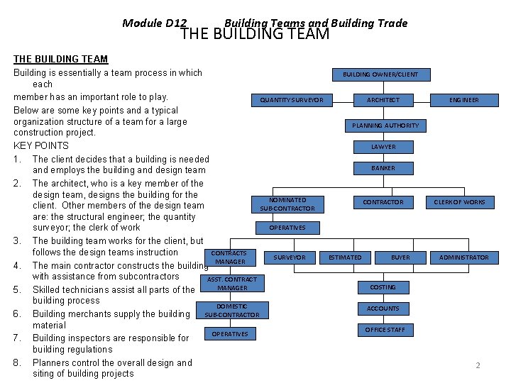
Module D 12 Building Teams and Building Trade THE BUILDING TEAM Building is essentially a team process in which each member has an important role to play. QUANTITY SURVEYOR Below are some key points and a typical organization structure of a team for a large construction project. KEY POINTS 1. The client decides that a building is needed and employs the building and design team 2. The architect, who is a key member of the design team, designs the building for the NOMINATED client. Other members of the design team SUB-CONTRACTOR are: the structural engineer; the quantity OPERATIVES surveyor; the clerk of work 3. The building team works for the client, but follows the design teams instruction CONTRACTS SURVEYOR 4. The main contractor constructs the building MANAGER with assistance from subcontractors ASST. CONTRACT MANAGER 5. Skilled technicians assist all parts of the building process DOMESTIC SUB-CONTRACTOR 6. Building merchants supply the building material OPERATIVES 7. Building inspectors are responsible for building regulations 8. Planners control the overall design and siting of building projects BUILDING OWNER/CLIENT ARCHITECT ENGINEER PLANNING AUTHORITY LAWYER BANKER CONTRACTOR ESTIMATED BUYER CLERK OF WORKS ADMINISTRATOR COSTING ACCOUNTS OFFICE STAFF 2

Functions of the members of the Building Team Client – the person who commissions the work and directly or indirectly employs everybody on the project. Architect – engaged by the client as his/her agent to design, advise and ensure that the project is keeping within cost and complies with the design. Contractor – employed by the client on the architect’s advice to carry out the constructional works. He takes his instructions from the architect. Engineer – a specialist such as a structural engineer employed to work with the architect on particular aspects of the design. Quantity surveyor – engaged to prepare bills of quantities, check tenders, prepare interim valuations and advise the architect on the cost of variations
Building Trades • The building industry has a number of trades associated with it. These include: – Carpenter – Mason/tiler – Painter – Electrician – Plumber

Responsibility of members of the Building Trade • Carpenter – erects structural framework and constructs roofs • Electrician – carries out wiring works and installation of fixtures • Plumber – lay pipes, install taps, toilet bowls, etc. • Painter – responsible for finishing the building by applying paint, wall paper • Mason/tiler – works with concrete and mortar, lay concrete blocks, plaster walls etc.
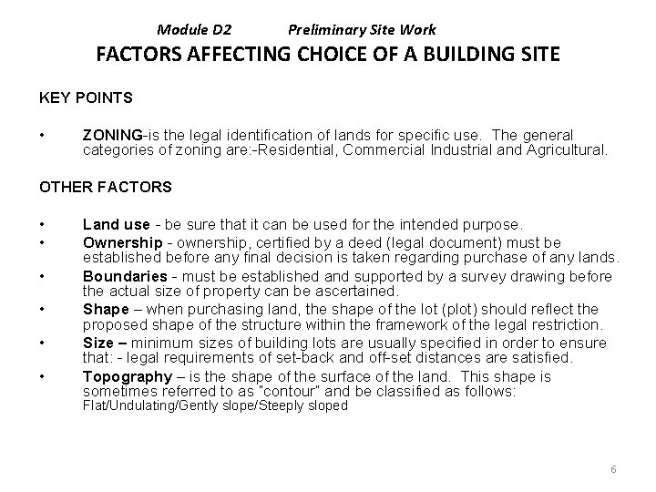
Module D 2 Preliminary Site Work FACTORS AFFECTING CHOICE OF A BUILDING SITE KEY POINTS • ZONING-is the legal identification of lands for specific use. The general categories of zoning are: -Residential, Commercial Industrial and Agricultural. OTHER FACTORS • • • Land use - be sure that it can be used for the intended purpose. Ownership - ownership, certified by a deed (legal document) must be established before any final decision is taken regarding purchase of any lands. Boundaries - must be established and supported by a survey drawing before the actual size of property can be ascertained. Shape – when purchasing land, the shape of the lot (plot) should reflect the proposed shape of the structure within the framework of the legal restriction. Size – minimum sizes of building lots are usually specified in order to ensure that: - legal requirements of set-back and off-set distances are satisfied. Topography – is the shape of the surface of the land. This shape is sometimes referred to as “contour” and be classified as follows: Flat/Undulating/Gently slope/Steeply sloped 6
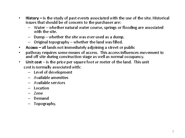
History – is the study of past events associated with the use of the site. Historical issues that should be of concern to the purchaser are: – Water – whether natural water course, springs or flooding are associated with the site. – Dump – whether the site was ever used as a dump. – Original topography – whether the land was filled. • Access – all lands not immediately adjoining a street or public • pathway requires some means of access. This access influences movement to and off site during construction stage as well as normal occupancy. • Unit cost – is the price per square foot or meter of the land. This unit cost is normally associated with: – Level of development – Available amenities – Available services – Location – Zone – Demand – Topography. • 7
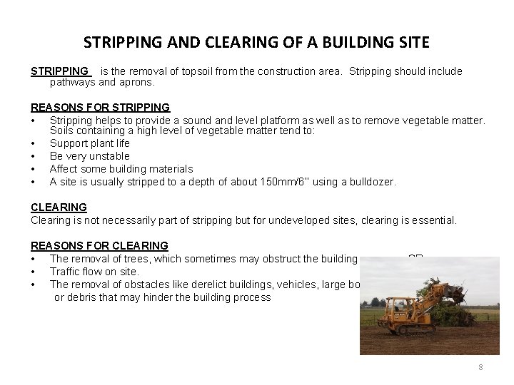
STRIPPING AND CLEARING OF A BUILDING SITE STRIPPING is the removal of topsoil from the construction area. Stripping should include pathways and aprons. REASONS FOR STRIPPING • Stripping helps to provide a sound and level platform as well as to remove vegetable matter. Soils containing a high level of vegetable matter tend to: • Support plant life • Be very unstable • Affect some building materials • A site is usually stripped to a depth of about 150 mm/6’’ using a bulldozer. CLEARING Clearing is not necessarily part of stripping but for undeveloped sites, clearing is essential. REASONS FOR CLEARING • The removal of trees, which sometimes may obstruct the building process. OR • Traffic flow on site. • The removal of obstacles like derelict buildings, vehicles, large boulders or debris that may hinder the building process 8
Hoarding One of the first jobs is to lay out the site boundaries, this is known as hoarding. This is done for the following reasons: Reasons for hoarding: • - Public protection • - Material/equipment protection • - Security • - Reduces vandalism • - Prevents interruption Explanatory notes for reasons given: • Public protection – to reduce the risk of accidents by keeping activities on the site away from outside persons • Material/equipment protection – to reduce theft of materials • Security – to ensure workers and equipment are safe on the site. • Reduces vandalism – prevents persons from interfering or destroying items on the site. • Prevents interruption – persons or animals from the outside would not be able to distract workers on the site
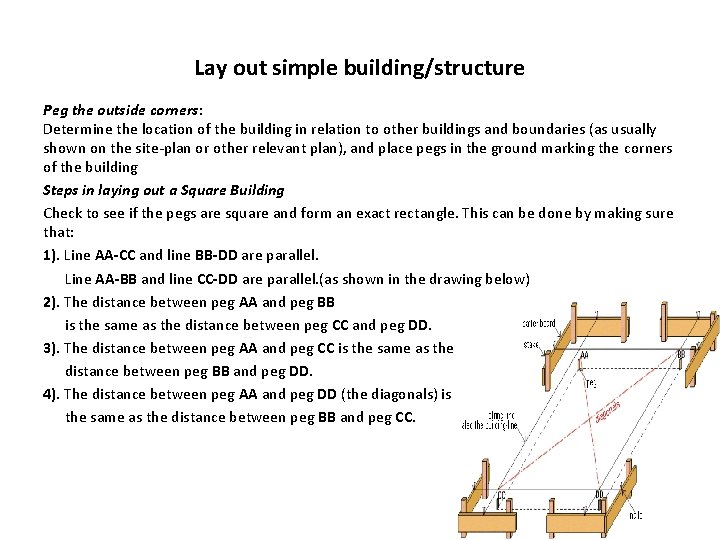
Lay out simple building/structure Peg the outside corners: Determine the location of the building in relation to other buildings and boundaries (as usually shown on the site-plan or other relevant plan), and place pegs in the ground marking the corners of the building Steps in laying out a Square Building Check to see if the pegs are square and form an exact rectangle. This can be done by making sure that: 1). Line AA-CC and line BB-DD are parallel. Line AA-BB and line CC-DD are parallel. (as shown in the drawing below) 2). The distance between peg AA and peg BB is the same as the distance between peg CC and peg DD. 3). The distance between peg AA and peg CC is the same as the distance between peg BB and peg DD. 4). The distance between peg AA and peg DD (the diagonals) is the same as the distance between peg BB and peg CC.
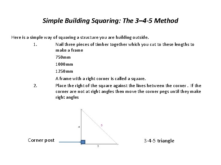
Simple Building Squaring: The 3– 4 -5 Method Here is a simple way of squaring a structure you are building outside. 1. Nail three pieces of timber together which you cut to these lengths to make a frame 750 mm 1000 mm 1250 mm A frame with a right corner is called a square. 2. Place the right of the square against the lines between the corner. If the corner are not at right angles then move the corner pegs until they make right angles Corner post 3 -4 -5 triangle
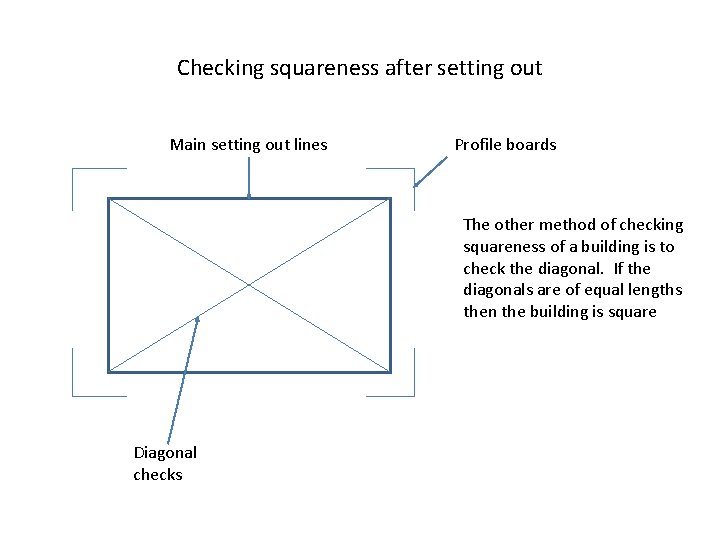
Checking squareness after setting out Main setting out lines Profile boards The other method of checking squareness of a building is to check the diagonal. If the diagonals are of equal lengths then the building is square Diagonal checks
TEMPORARY SERVICES ON A BUILDING SITE • • • • DEFINITION Temporary services relate to the provision of utilities for the purpose of facilitating construction activities as well as providing convenience for workers. These supplies normally include: gas, water, compressed air, electricity and telephone. CONVENIENCES These include convenience for personnel and work processes. PERSONNEL: Temporary services assist in the provision of drinking water, adequate lighting and toilet facilities. WORK PROCESSES: Utility supplies to the site can be used to drive (power) plant and equipment or provide ingredients for preparing certain materials. Examples of supplies used for driving plant and equipment are: Air – pneumatic tools and equipment Oil and gas – turbine and hydraulic tools and equipment. Electricity – electric tools and equipment Heat, water and air are used in the following processes: Heat – asphaltic processes Water – mixing concrete Air – spray painting, excavating compacting COMMUNICATION Communication includes physical and verbal contact between the various agencies and processes during the life of the project. Factors to be considered are temporary roads for access to the site and storage areas, as well as possible telephone or two-way radio contacts. 13
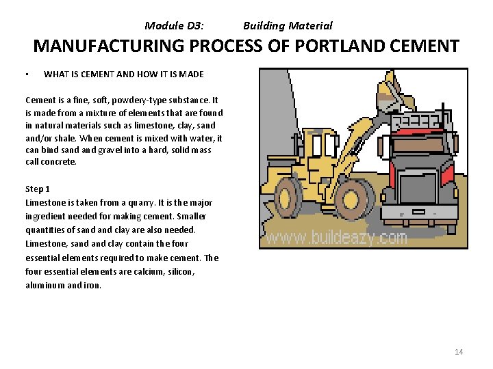
Module D 3: Building Material MANUFACTURING PROCESS OF PORTLAND CEMENT • WHAT IS CEMENT AND HOW IT IS MADE Cement is a fine, soft, powdery-type substance. It is made from a mixture of elements that are found in natural materials such as limestone, clay, sand and/or shale. When cement is mixed with water, it can bind sand gravel into a hard, solid mass call concrete. Step 1 Limestone is taken from a quarry. It is the major ingredient needed for making cement. Smaller quantities of sand clay are also needed. Limestone, sand clay contain the four essential elements required to make cement. The four essential elements are calcium, silicon, aluminum and iron. 14
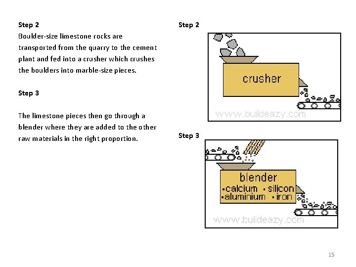
Step 2 Boulder-size limestone rocks are transported from the quarry to the cement plant and fed into a crusher which crushes the boulders into marble-size pieces. Step 2 Step 3 The limestone pieces then go through a blender where they are added to the other raw materials in the right proportion. Step 3 15
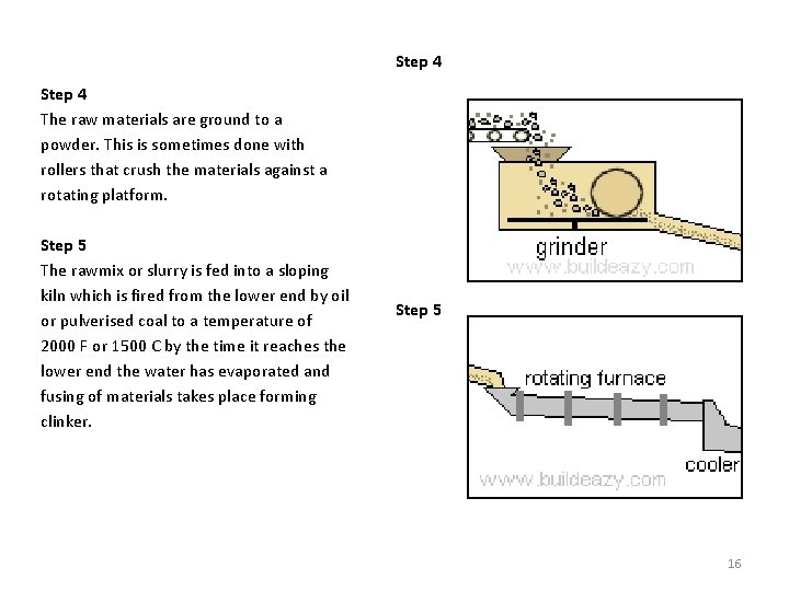
Step 4 The raw materials are ground to a powder. This is sometimes done with rollers that crush the materials against a rotating platform. Step 5 The rawmix or slurry is fed into a sloping kiln which is fired from the lower end by oil or pulverised coal to a temperature of 2000 F or 1500 C by the time it reaches the lower end the water has evaporated and fusing of materials takes place forming clinker. Step 5 16
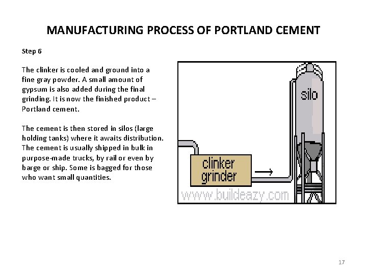
MANUFACTURING PROCESS OF PORTLAND CEMENT Step 6 The clinker is cooled and ground into a fine gray powder. A small amount of gypsum is also added during the final grinding. It is now the finished product – Portland cement. The cement is then stored in silos (large holding tanks) where it awaits distribution. The cement is usually shipped in bulk in purpose-made trucks, by rail or even by barge or ship. Some is bagged for those who want small quantities. 17
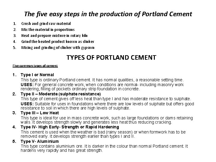
The five easy steps in the production of Portland Cement 1. 2. 3. 4. 5. Crush and grind raw material Mix the material in proportions Heat and prepare mixture in rotary kiln Grind the heated product known as clinker Mixing and grinding of clinker with gypsum TYPES OF PORTLAND CEMENT Five common types of cement 1. 2. 3. 4. 5. Type I or Normal This type is ordinary Portland cement. It has normal qualities, a reasonable setting time. USES: For general concrete work, when conditions are normal- including masonry work rendering, filling of pockets ordinary strip foundation in concrete. Type II – Moderate (sulphate resistance) This type of cement gives off less heat than type I and has moderate resistance to sulphate. USES: Suitable for uses in foundations where there are low levels of sulphate but offers good resistance to soil in which there are high levels of sulphate. Type III – Low Heat This type is ideal for use in mass concrete work, such as large foundations or dams retaining walls. It develops strength slowly and generates less heat thus reducing cracking. Type IV- High Early- Strength or Rapid Hardening This cement is used when the weather is bad (rainy season) or when formwork has to be removed early. It develops strength earlier than types I and II. Type V- Aluminium This type contains aluminium ore. It is darker in the colour than normal Portland cement. It hardens very rapidly and has great strength.
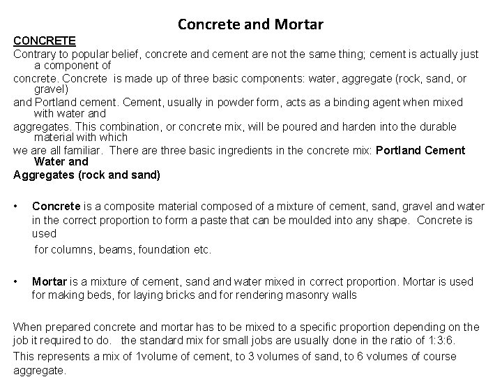
Concrete and Mortar CONCRETE Contrary to popular belief, concrete and cement are not the same thing; cement is actually just a component of concrete. Concrete is made up of three basic components: water, aggregate (rock, sand, or gravel) and Portland cement. Cement, usually in powder form, acts as a binding agent when mixed with water and aggregates. This combination, or concrete mix, will be poured and harden into the durable material with which we are all familiar. There are three basic ingredients in the concrete mix: Portland Cement Water and Aggregates (rock and sand) • Concrete is a composite material composed of a mixture of cement, sand, gravel and water in the correct proportion to form a paste that can be moulded into any shape. Concrete is used for columns, beams, foundation etc. • Mortar is a mixture of cement, sand water mixed in correct proportion. Mortar is used for making beds, for laying bricks and for rendering masonry walls When prepared concrete and mortar has to be mixed to a specific proportion depending on the job it required to do. the standard mix for small jobs are usually done in the ratio of 1: 3: 6. This represents a mix of 1 volume of cement, to 3 volumes of sand, to 6 volumes of course aggregate.
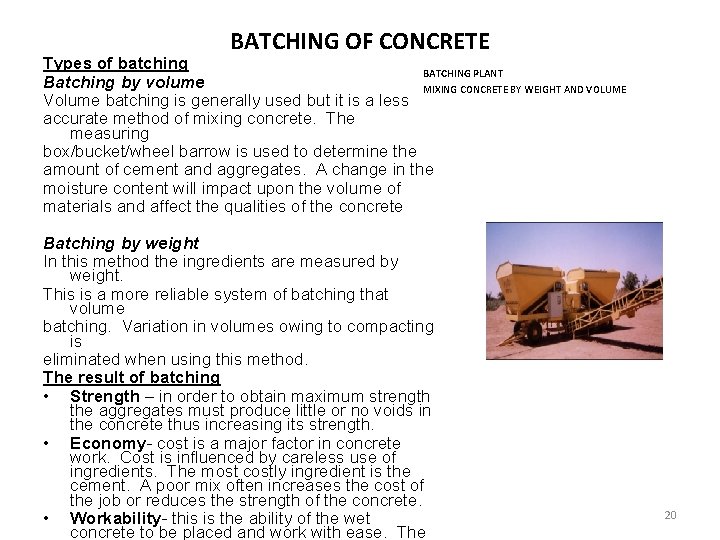
BATCHING OF CONCRETE Types of batching BATCHING PLANT Batching by volume MIXING CONCRETE BY WEIGHT AND VOLUME Volume batching is generally used but it is a less accurate method of mixing concrete. The measuring box/bucket/wheel barrow is used to determine the amount of cement and aggregates. A change in the moisture content will impact upon the volume of materials and affect the qualities of the concrete Batching by weight In this method the ingredients are measured by weight. This is a more reliable system of batching that volume batching. Variation in volumes owing to compacting is eliminated when using this method. The result of batching • Strength – in order to obtain maximum strength the aggregates must produce little or no voids in the concrete thus increasing its strength. • Economy- cost is a major factor in concrete work. Cost is influenced by careless use of ingredients. The most costly ingredient is the cement. A poor mix often increases the cost of the job or reduces the strength of the concrete. • Workability- this is the ability of the wet concrete to be placed and work with ease. The 20
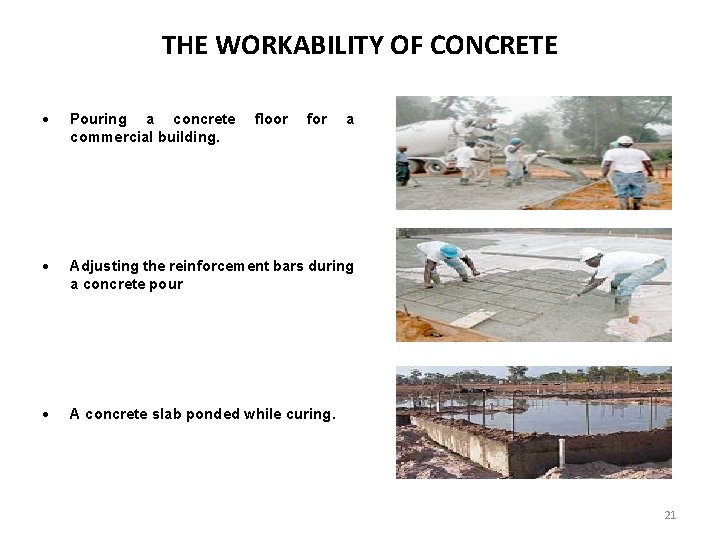
THE WORKABILITY OF CONCRETE Pouring a concrete commercial building. Adjusting the reinforcement bars during a concrete pour A concrete slab ponded while curing. floor for a 21
AGGREGATES Aggregates is the general terms for the sand rocks used in construction. Fine aggregates are sand coarse aggregates are gravel or crushed stone. Aggregates are size graded and sold by set size categories, measured as inches or millimetres. Requirements of Aggregates • All aggregates should be: • Clean • Free from all sediment • Strong not easily crushed • Well graded • Well shaped Types of Aggregates • Coarse Aggregate gravel consists of small pieces of stone which are somewhat rounded in shape. It makes good coarse aggregate because it is hard and closed textured. When using gravel as a coarse aggregate the pebbles should be graded in size – (Source – Gravel Bank, River Beds). • Crushed Stone trap rock is the hardest and most durable stone that can be crushed and used for making concrete. This stone is dark, heavy, close-grained, and of igneous origin. Granite makes good crushed stone and is less expensive than trap rock. • Fine Aggregates for concrete are sand crushed stone or gravel screening. The most important of thee (by far) is sand. Sand is a finely divided material of rock or mineral origin which will pass through a standard 5 mm sieve. Sand is not subject to disintegration, decay or expansion. 22 • All–in: The term all-in is used for aggregates composed of both fine and coarse
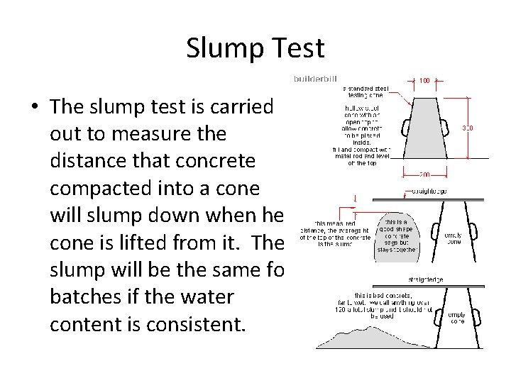
Slump Test • The slump test is carried out to measure the distance that concrete compacted into a cone will slump down when he cone is lifted from it. The slump will be the same for batches if the water content is consistent.
Placing Concrete The following are precautions to be taken when placing concrete: 1. Mixed concrete should be placed in its final position within half to an hour of mixing. This is because the initial setting of ordinary Portland cement takes place within this period of time. After this time, the concrete has lost some strength which can never be regained. 2. Concreting in hot dry weather poses particular problems with regards to placing. Moisture evaporates too fast rapid and this can result in a weak finished product. 3. When concrete is being laid in foundation trenches, in addition to the fast evaporation of moisture from the concrete, the dry trench absorbs moisture from the concrete. To limit this absorption, the trench should be watered down before the concrete is placed into it 4. Concrete shouldn’t be dropped from a great height, as this tends to segregate the aggregate. A height of 1 meter is usually specified as the maximum from which wet concrete should be allowed to drop freely 5. Soon after placing in the right position concrete should be compacted or consolidated. The purpose of compacting is to make the concrete as dense as possible by eliminating voids within it. 6. All formwork must be plumbed, leveled and adequately supported.
CURING AND PROTECTING CONCRETE Curing is the process of limiting early loss of water from concrete thus ensuring the continuation of chemical action. Losing too much water too early in the life of a concrete component causes high creep and shrinkage, and may even cause a significant loss of strength. Most importantly, poor curing is detrimental to the durability of the concrete, particularly the outer concrete which is required to provide protection to the embedded reinforcement. In general, the longer the period of curing, the better will be the quality of the concrete. This applies not only to its compressive strength, but also to its durability, its resistance to wear, weathering and chemical attack, and to its freedom from shrinkage cracking. Concrete therefore needs to be kept moist, both by the prevention of loss of moisture due to evaporation, and by the provision of extra water from outside the concrete. There are two general forms of curing: • Keeping all concrete surfaces wet to prevent moisture loss (spraying with water) • Creating a barrier to prevent moisture loss (sandbags, ponding)
D 3. 2: Plastics and Water proofing Material THE USE OF PLASTICS IN THE CONSTRUCTION INDUSTRIES Properties of Plastics Lightweight Durable Easily jointed or molded Glazable Elastic Uses of Plastic in Construction Electrical conduits Water seals, (DPC) Damp Proof Coarse, (DPM) Damp Proof Membranes • Floor/roof tiles • Decorative skirtings/mouldings • Water pipes • Drain pipes Conclusion: With the increase of modern technology plastics have not only make a big impact in the construction industry but in other areas such as medicine (prosthetic, plastic surgery), transportation (vehicle manufacturing) and communication (fiber optic cables and cell phones). • • • 26
D 3. 3: Timber and Timber Products GROWTH AND STRUCTURE OF TIMBER • SECTION OF A TREE TRUNK The Parts of a Tree Trunk • Bark – Every species of tree has its own particular kind of bark. This is a means of identification. The bark is the protective coating of the tree. • Cambium Layer – This is the growing part of the tree trunk. Here new cells are constantly developing, some making bark and others making wood. • Sapwood – This is found next to the cambium layer, and contains only a few living cells and functions mainly in the storage of plant food and the conveyance of sap. The sapwood varies in thickness from 13 mm to as much as 150 mm radial thickness in some species. • Heart Wood – It consists of inactive cells that have slightly changed both chemically and physically from cells found in sapwood. These cells cease to transport sap. The cells of heartwood may contain minerals, which contribute to its darker colour, great beauty and resistance to decay. 27
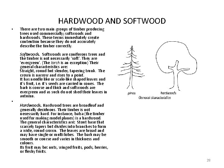
HARDWOOD AND SOFTWOOD • • There are two main groups of timber producing trees used commercially; softwoods and hardwoods. These terms immediately create contention because they do not accurately describe the timber correctly. Softwoods are coniferous trees and the timber is not necessarily 'soft'. They are 'evergreen'. (The larch is an exception) Their general characteristics are: Straight, round but slender, tapering trunk. The crown is narrow and rises to a point. It has needle like or scale-like shaped leaves and it's fruit, i. e. it's seeds are carried in cones. The bark is course and thick and softwoods are evergreen and as such do not shed their leaves in autumn. Hardwoods. Hardwood trees are broadleaf and generally deciduous. Their timber is not necessarily hard. For instance, balsa (the timber used for making model planes) is a hardwood. The general characteristics are: Stout base that scarcely tapers but divides into branches to form a wide, round crown. The leaves are broad and may have single or multi lobes. The bark may be smooth or course and varies in thickness and colours. Its fruit may be: nuts, winged fruits, pods, berries, or fleshy fruits. 28
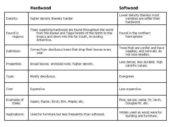
Hardwood Softwood Density: higher density thereby harder Lower density thereby most varieties are softer than hardwood. Found in regions: Trees supplying hardwood are found throughout the world from the Boreal and Taiga forests of the North to the tropics and down into the far South, excluding Antarctica. Found in the northern hemisphere. Definition: Comes from deciduous trees that drop their leaves every year. Trees that are conifer and have needles, and normally do not lose needles. Properties: Broad leaves; enclosed nuts; higher density. Less dense; less durable; high calorific values. Type: Mostly deciduous. Evergreen Cost Expensive. Less expensive. Examples of trees: Aspen, Poplar, Birch, Elm, Maple, etc. Pine, spruce, cedar, fir, larch, Douglas-fir, etc. Applications: Used for furniture but less frequently than softwood. Widely used as wood ware for building and furniture.
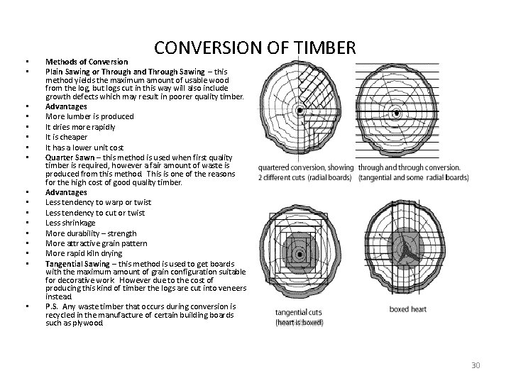
• • • • • CONVERSION OF TIMBER Methods of Conversion Plain Sawing or Through and Through Sawing – this method yields the maximum amount of usable wood from the log, but logs cut in this way will also include growth defects which may result in poorer quality timber. Advantages More lumber is produced It dries more rapidly It is cheaper It has a lower unit cost Quarter Sawn – this method is used when first quality timber is required, however a fair amount of waste is produced from this method. This is one of the reasons for the high cost of good quality timber. Advantages Less tendency to warp or twist Less tendency to cut or twist Less shrinkage More durability – strength More attractive grain pattern More rapid kiln drying Tangential Sawing – this method is used to get boards with the maximum amount of grain configuration suitable for decorative work. However due to the cost of producing this kind of timber the logs are cut into veneers instead. P. S. Any waste timber that occurs during conversion is recycled in the manufacture of certain building boards such as plywood. 30
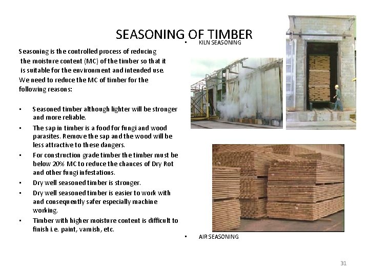
SEASONING • OFKILNTIMBER SEASONING Seasoning is the controlled process of reducing the moisture content (MC) of the timber so that it is suitable for the environment and intended use. We need to reduce the MC of timber for the following reasons: • • • Seasoned timber although lighter will be stronger and more reliable. The sap in timber is a food for fungi and wood parasites. Remove the sap and the wood will be less attractive to these dangers. For construction grade timber the timber must be below 20% MC to reduce the chances of Dry Rot and other fungi infestations. Dry well seasoned timber is stronger. Dry well seasoned timber is easier to work with and consequently safer especially machine working. Timber with higher moisture content is difficult to finish i. e. paint, varnish, etc. • AIR SEASONING 31
TYPES OF SEASONING There are two main ways of seasoning timber, Natural (Air) and Artificial (Kiln) drying. Both methods require the timber be stacked and separated to allow the full circulation flow of air, etc. around the stack. Kiln Seasoning. There are two main methods used in artificial seasoning, compartmental, and progressive. Both methods rely on the controlled environment to dry out the timber and require the following factors: Air Seasoning. Air seasoning is the method used with the timber stacked in the open air. It requires the following: • Stacked stable and safely with horizontal spacing of at least 25 mm. • Vertical spacing achieved by using timber battens (piling sticks) of the same or neutral species. Today some timber yards are using plastics. The piling sticks should be vertically aligned and spaced close enough to prevent bowing say 600 to 1200 mm max centres. • Ends of boards sealed by using a suitable sealer or cover to prevent too rapid drying out via the end grain. • The stack raised well clear of the ground, vegetation, etc to provide good air circulation and free from rising damp, frost, etc. • Over head cover from effects of direct sunlight and driving weather. • • • Forced air circulation by using large fans, blowers, etc. Heat of some form provided by piped steam. Humidity control provided by steam jets. The amount and duration of air, heat and humidity again depends on species, size, quantity, etc. Schedules are published for the various species to enable operators to select an appropriate drying environment. In the UK they are usually provided by the Kiln Manufacturers and also published in the Handbook of Hardwoods and Handbook of Softwoods (BRE). 32
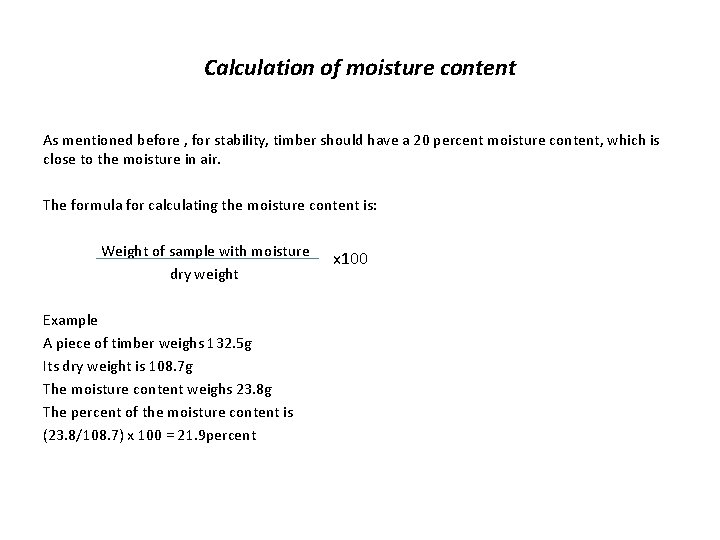
Calculation of moisture content As mentioned before , for stability, timber should have a 20 percent moisture content, which is close to the moisture in air. The formula for calculating the moisture content is: Weight of sample with moisture dry weight Example A piece of timber weighs 132. 5 g Its dry weight is 108. 7 g The moisture content weighs 23. 8 g The percent of the moisture content is (23. 8/108. 7) x 100 = 21. 9 percent x 100
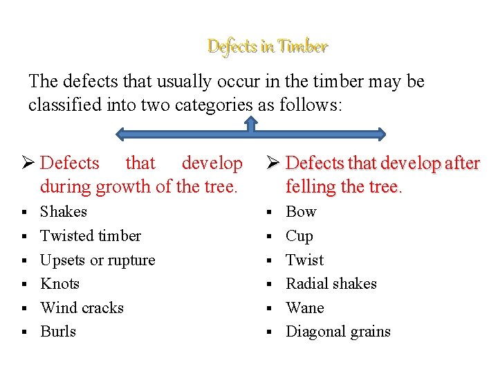
Defects in Timber The defects that usually occur in the timber may be classified into two categories as follows: Ø Defects that develop during growth of the tree. § § § Shakes Twisted timber Upsets or rupture Knots Wind cracks Burls Ø Defects that develop after felling the tree. § § § Bow Cup Twist Radial shakes Wane Diagonal grains
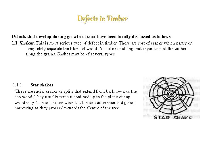
Defects in Timber Defects that develop during growth of tree have been briefly discussed as follows: 1. 1 Shakes. This is most serious type of defect in timber. These are sort of cracks which partly or completely separate the fibers of wood. A shake is nothing, but separation of the timber along the grains. Shakes may be of several types. 1. 1. 1 Star shakes These are radial cracks or splits that extend from bark towards the sap wood. They usually remain confined up to the plane of sap wood only. The cracks are widest at the circumference and go on narrowing as they proceed towards the Centre of the tree.
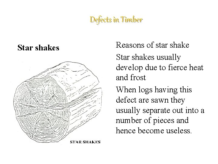
Defects in Timber Star shakes Reasons of star shake Star shakes usually develop due to fierce heat and frost When logs having this defect are sawn they usually separate out into a number of pieces and hence become useless.
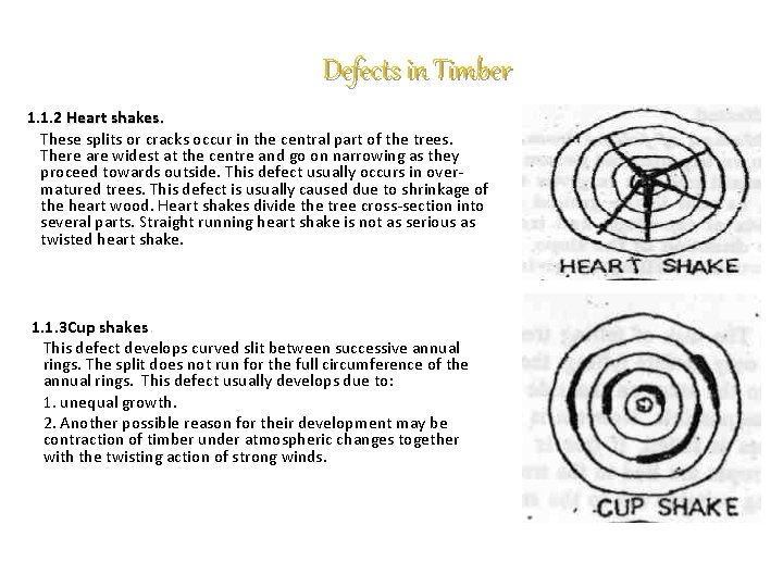
Defects in Timber 1. 1. 2 Heart shakes. These splits or cracks occur in the central part of the trees. There are widest at the centre and go on narrowing as they proceed towards outside. This defect usually occurs in overmatured trees. This defect is usually caused due to shrinkage of the heart wood. Heart shakes divide the tree cross-section into several parts. Straight running heart shake is not as serious as twisted heart shake. 1. 1. 3 Cup shakes. This defect develops curved slit between successive annual rings. The split does not run for the full circumference of the annual rings. This defect usually develops due to: 1. unequal growth. 2. Another possible reason for their development may be contraction of timber under atmospheric changes together with the twisting action of strong winds.
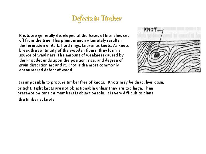
1. 4 Knots. Defects in Timber Knots are generally developed at the bases of branches cut off from the tree. This phenomenon ultimately results in the formation of dark, hard rings, known as knots. As knots break the continuity of the wooden fibers, they form a source of weakness. The amount of weakness caused by the knot depends upon the position, size, and degree of grain distortion around it. Knot is the most commonly encountered defect of wood. It is impossible to procure timber free of knots. Knots may be dead, live loose, or tight. Tight knots are not objectionable unless they are too large. Their presence on tension members is objectionable. It is very difficult to plane the timber at knots
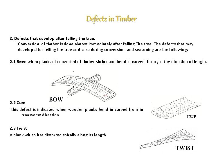
Defects in Timber 2. Defects that develop after felling the tree. Conversion of timber is done almost immediately after felling The tree. The defects that may develop after felling the tree and also during conversion and seasoning are the following: 2. 1 Bow: when planks of converted of timber shrink and bend in curved form , in the direction of length. 2. 2 Cup: this defect is indicated when wooden planks bend in curved from in transverse direction. 2. 3 Twist A plank which has distorted spirally along its length
Preserving Timber • Timber should have two types of preservation applied 1. Treatments of resist attack by rot fungus and wood-eating insects. 2. Treatment such as paint, polish or vanish to protect it from moisture and pollution Timber to be treated with preservative should be cut, shaped and prepared in advance of the building work. Ant cutting afterwards exposes untreated timber, which must have liquid preservative applied by hand. Two methods can be used to treat timber: 1. pressure impregnation 2. Steeping or immersion Pressure impregnation is a method whereby you put the timber in a kiln or other container and create a vacuum inside by pumping out the air. You use pressure to force the preservative deeply into the timber Steeping or immersion is a method where you put the timber in a tank filled with preservative. The timber absorbs so much liquid that it is full of the chemical preservative when it dries out again Advantages of Treated Timber • It provides long life under hazardous conditions. • It is cost efficient. • It is versatile – can be used outdoors, indoors, above ground, underground, and in direct contact with fresh or salt water. • A variety of finishes provide additional attractiveness. • It provides flexibility for design and can economically overcome difficult site situations. 40
MANUFACTURED BOARDS Manufactured or man made boards - are made from wood products and have new/different properties to the wood they were made from. Board sizes are 8 ft x 4 ft (2440 x 1220 mm). Properties of Manufactured board: 1. Larder size the nun manufactured board 2. Uniform texture 3. Smooth surface 4. Standard dimension 8 ft x 4 ft (2440 x 1220 mm) • MDF (medium density fibreboard) made by a process which glues wood fibres together using heat and pressure. The boards are smooth and strong. They are resistant to warping. They have a layered structure which makes fixing to the edges difficult. MDF is a board used industrially for the production of furniture (especially shelves and cupboards). Special fixings have been designed to enable MDF to be joined effectively. Dowel joints can be used. The router can be used to cut rebates and housing joints, which work well on MDF. Dust is a problem when working with MDF, dust extraction systems should be used when machining it. Face masks can also be used to reduce the problem Plywood is made from layers of thin wood glued together at 90 degrees to each other, this makes plywood very strong as it cannot split along the grain like solid timber. If waterproof glue is used the plywood can be used in damp or even wet conditions. Marine ply can withstand sea water. Aero ply is made from three thin layers of birch and is only one mm thick when bonded together, this ply was designed to be used on aeroplane wings as it can be curved so effectively 41
MANUFACTURED BOARDS • Hardboard manufacture consists of breaking down wood into its basic fibers then putting the wood back together with the fibers rearranged to form hard panels which have their own set of separate and distinct characteristics. In a most real sense “hardboard” is hard board. It is made in sheets in a wide variety of thicknesses but most commonly 1/8” to 1/4”. It is made from wood but is more dense. Placed in water many hardboard products will sink or barely float. It is hard on saws.
D 3. 4: Ironmongery
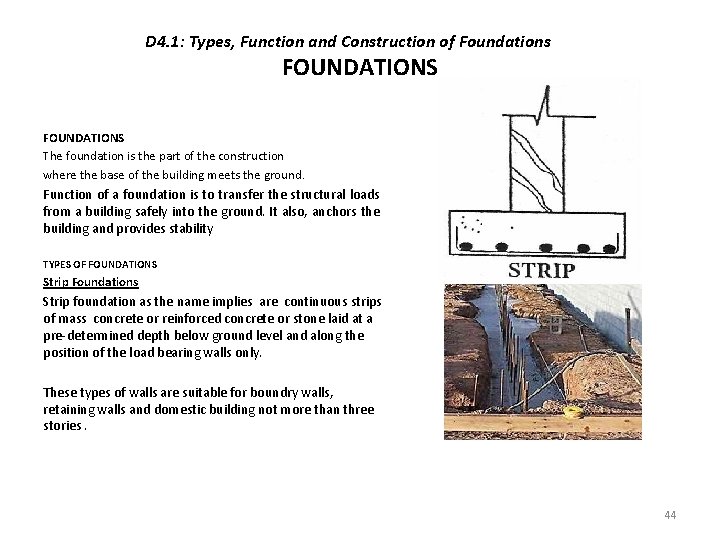
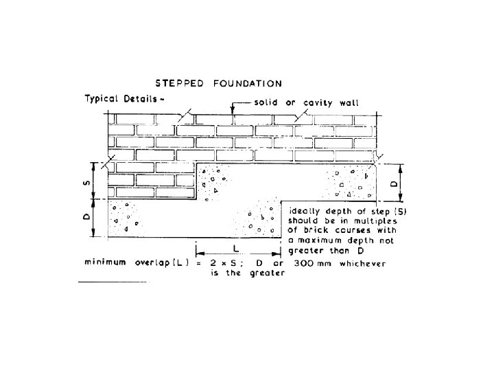
D 4. 1: Types, Function and Construction of Foundations FOUNDATIONS The foundation is the part of the construction where the base of the building meets the ground. Function of a foundation is to transfer the structural loads from a building safely into the ground. It also, anchors the building and provides stability TYPES OF FOUNDATIONS Strip Foundations Strip foundation as the name implies are continuous strips of mass concrete or reinforced concrete or stone laid at a pre-determined depth below ground level and along the position of the load bearing walls only. These types of walls are suitable for boundry walls, retaining walls and domestic building not more than three stories. 44
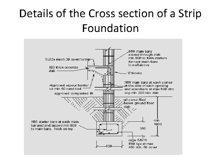
Details of the Cross section of a Strip Foundation
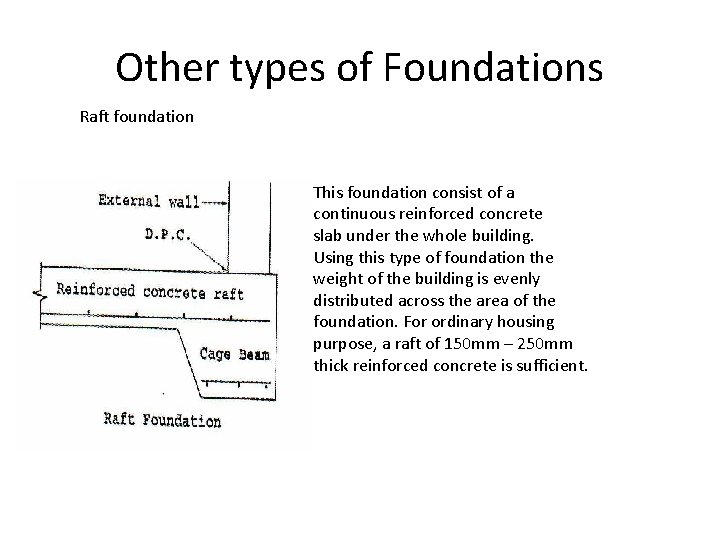
Other types of Foundations Raft foundation This foundation consist of a continuous reinforced concrete slab under the whole building. Using this type of foundation the weight of the building is evenly distributed across the area of the foundation. For ordinary housing purpose, a raft of 150 mm – 250 mm thick reinforced concrete is sufficient.
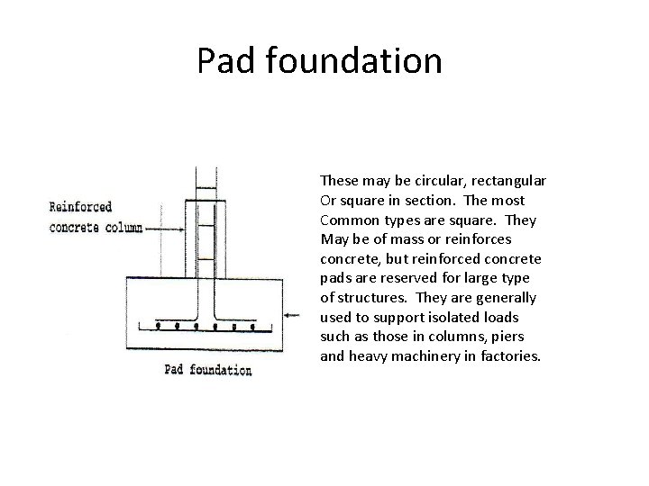
Pad foundation These may be circular, rectangular Or square in section. The most Common types are square. They May be of mass or reinforces concrete, but reinforced concrete pads are reserved for large type of structures. They are generally used to support isolated loads such as those in columns, piers and heavy machinery in factories.
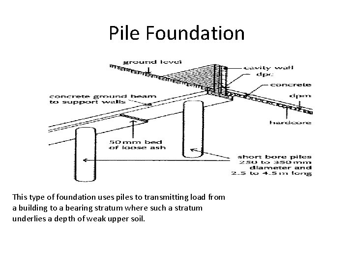
Pile Foundation This type of foundation uses piles to transmitting load from a building to a bearing stratum where such a stratum underlies a depth of weak upper soil.
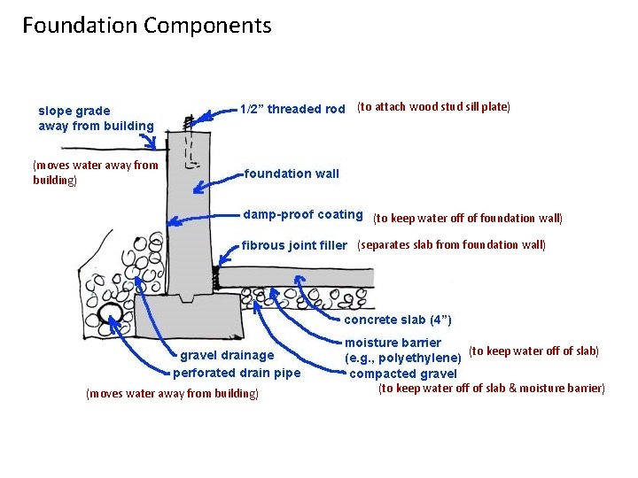
Foundation Components (to attach wood stud sill plate) (moves water away from building) (to keep water off of foundation wall) (separates slab from foundation wall) (to keep water off of slab) (moves water away from building) (to keep water off of slab & moisture barrier)
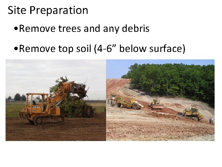
Site Preparation • Remove trees and any debris • Remove top soil (4 -6” below surface)
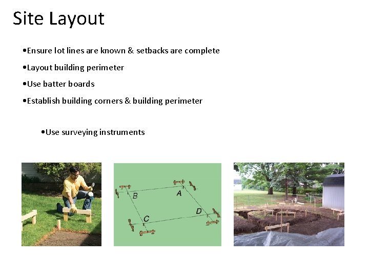
Site Layout • Ensure lot lines are known & setbacks are complete • Layout building perimeter • Use batter boards • Establish building corners & building perimeter • Use surveying instruments
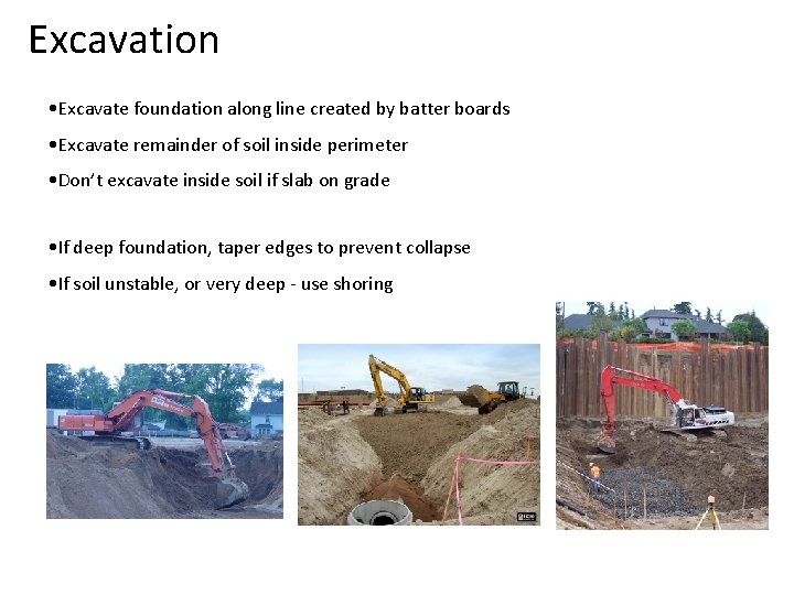
Excavation • Excavate foundation along line created by batter boards • Excavate remainder of soil inside perimeter • Don’t excavate inside soil if slab on grade • If deep foundation, taper edges to prevent collapse • If soil unstable, or very deep - use shoring
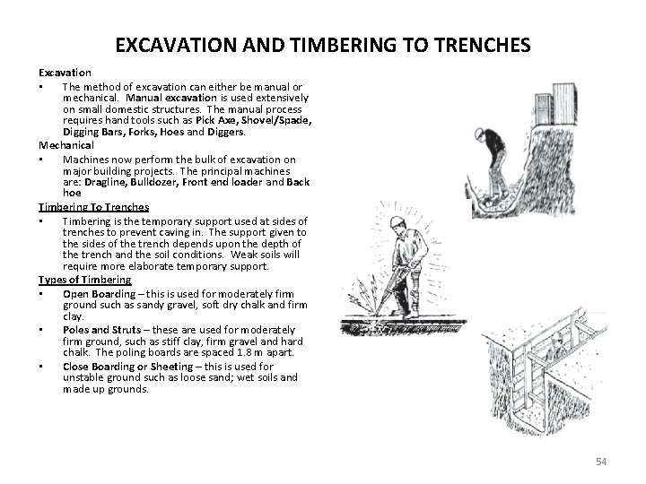
EXCAVATION AND TIMBERING TO TRENCHES Excavation • The method of excavation can either be manual or mechanical. Manual excavation is used extensively on small domestic structures. The manual process requires hand tools such as Pick Axe, Shovel/Spade, Digging Bars, Forks, Hoes and Diggers. Mechanical • Machines now perform the bulk of excavation on major building projects. The principal machines are: Dragline, Bulldozer, Front end loader and Back hoe Timbering To Trenches • Timbering is the temporary support used at sides of trenches to prevent caving in. The support given to the sides of the trench depends upon the depth of the trench and the soil conditions. Weak soils will require more elaborate temporary support. Types of Timbering • Open Boarding – this is used for moderately firm ground such as sandy gravel, soft dry chalk and firm clay. • Poles and Struts – these are used for moderately firm ground, such as stiff clay, firm gravel and hard chalk. The poling boards are spaced 1. 8 m apart. • Close Boarding or Sheeting – this is used for unstable ground such as loose sand; wet soils and made up grounds. 54
Module D 5: Walls Definition A wall is a continuous, usually vertical, solid structure of brick , stone, timber or metal which encloses and protects a building or serves to divide buildings into compartments or rooms They carry and transmit to the foundations the imposed vertical loads from other Building elements(beams, floors, and roofs) and ensure the stiffness of the whole structure. They also protect the structure from the horizontal actions of wind and earthquake, acting as wind bracing. Walls are defined as external or internal to differentiate functional requirements, and also as load bearing or non-load bearing to differentiate structural requirements. Load bearing walls, those that carry imposed loads, such as those transmitted by floors, roofs…; Non-load bearing walls which can carry just their own weight and if they are made of masonry are termed panel walls; Non-load bearing walls supported by other structural elements, those related to a framed structure
Functional requirements • The function of a wall is to enclose and protect a building or to divide space within the building. The main functional requirements are: • 1) Stability • 2) Strength • 3) Durability • 4) Weather resistance • 5) Fire resistance • 6) Thermal insulation • 7) Sound insulation
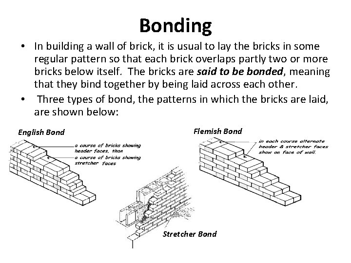
Bonding • In building a wall of brick, it is usual to lay the bricks in some regular pattern so that each brick overlaps partly two or more bricks below itself. The bricks are said to be bonded, meaning that they bind together by being laid across each other. • Three types of bond, the patterns in which the bricks are laid, are shown below: English Bond Flemish Bond Stretcher Bond
Setting out openings in Walls • Once the wall reaches ground level thought must be given to the position of the different openings. These openings are usually for doors, windows, frames and arches. The following terms are used when dealing with masonry: 1. 2. 3. 4. 5. 6. Lintels: Steel reinforced- concrete beams used for support over windows and doors Laying Block: The process of mixing mortar, applying it to masonry block, and placing the block to create walls. Course: A row of masonry units Masonry: Anything constructed of brick, stone, tile, or concrete unit held in place with portland concrete Concrete Sills: Used under windows and doors Footer or Footing: A continuous slab of concrete which provides a solid, level foundation for block or brick
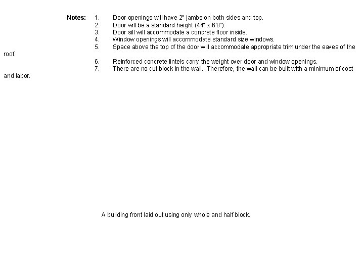
Notes: 1. 2. 3. 4. 5. Door openings will have 2" jambs on both sides and top. Door will be a standard height (44" x 6'8"). Door sill will accommodate a concrete floor inside. Window openings will accommodate standard size windows. Space above the top of the door will accommodate appropriate trim under the eaves of the 6. 7. Reinforced concrete lintels carry the weight over door and window openings. There are no cut block in the wall. Therefore, the wall can be built with a minimum of cost roof. and labor. A building front laid out using only whole and half block.
Procedure for laying blocks • • A. B. • C. • D. E. • F. • G. Spread a layer of mortar called a mortar bed as the footer. Position the block on the mortar bed so that its outside corner rests there the outside corner of the wall should be. Level the block by first placing the level across the block and then lengthwise along the block. Turn several stretcher blocks on end apply mortar to the ears with a wiping or swiping stroke of the trowel. Lay several stretcher blocks in place by working away from the end or corner block. Use the end of the trowel handle to tap the block until each block is plumb, level, and the course is straight. Apply a mortar bed on top of the first course in preparation for the second course. If extra strength is needed in the wall, install reinforcement in the mortar bed.
Procedure for laying blocks • • H. I. • J. • K. • L. • M. As the block laying progresses, cut off excess mortar with the trowel. Use a line to keep the courses straight. The line is positioned to be level along the top of the block. When a block must be cut, use a mason=s hammer and make multiple strikes along the line to cut; then make one sharp strike on the web. Check the height to be sure each new course is an additional 8 inches high. After the mortar dries and hardens slightly, finish the joints by rubbing it with a broken piece of block. If a joint other than a flush joint is desired, use a jointer to compress the mortar and create a watertight joint. Tools are available to create joints that are concave, v-shape, flush or raked.
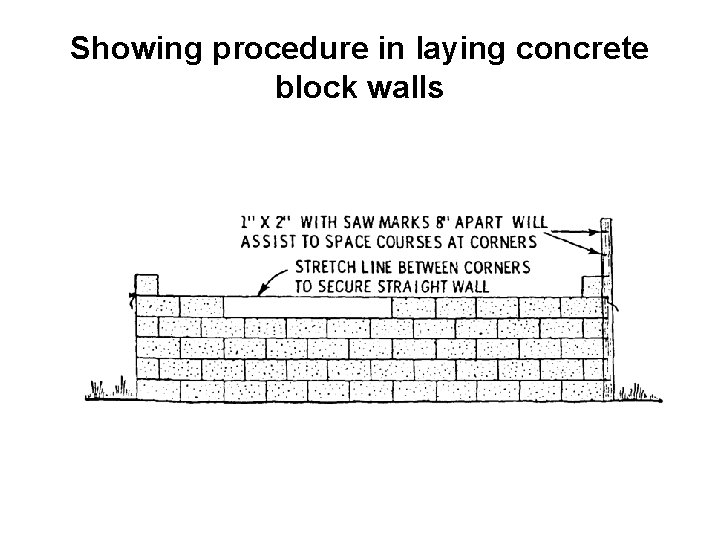
Showing procedure in laying concrete block walls
The usual practice in applying mortar to concrete blocks
A method of laying concrete blocks. Good workmanship requires straight courses with the face of the wall plumb and true.
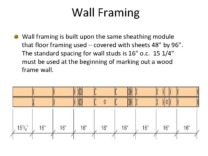
Wall Framing Wall framing is built upon the same sheathing module that floor framing used – covered with sheets 48” by 96”. The standard spacing for wall studs is 16” o. c. 15 1/4” must be used at the beginning of marking out a wood frame wall.
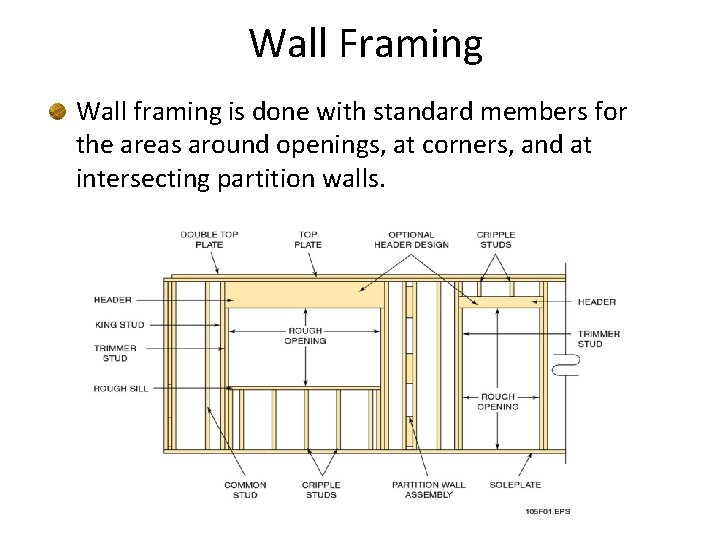
Wall Framing Wall framing is done with standard members for the areas around openings, at corners, and at intersecting partition walls.
What are the parts of a framed wall? (Figures 1) 1) Sole plate 2) Stud – usually placed 16” or 24” o. c. (on center 3) Cripple & trimmer studs – used in corners, window and door openings 4) Header 5) Top plate
Material information • What lumber sizes are used for the studs and plates? - 2 x 4’s or 2 x 6’s, depending upon climate or desired insulation • What lumber sizes are used for the headers? - 2 x 10 or 2 x 12
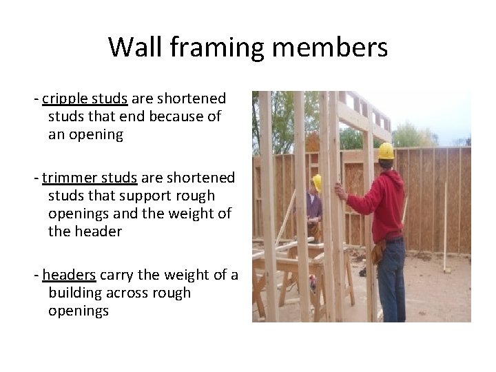
Wall framing members - cripple studs are shortened studs that end because of an opening - trimmer studs are shortened studs that support rough openings and the weight of the header - headers carry the weight of a building across rough openings
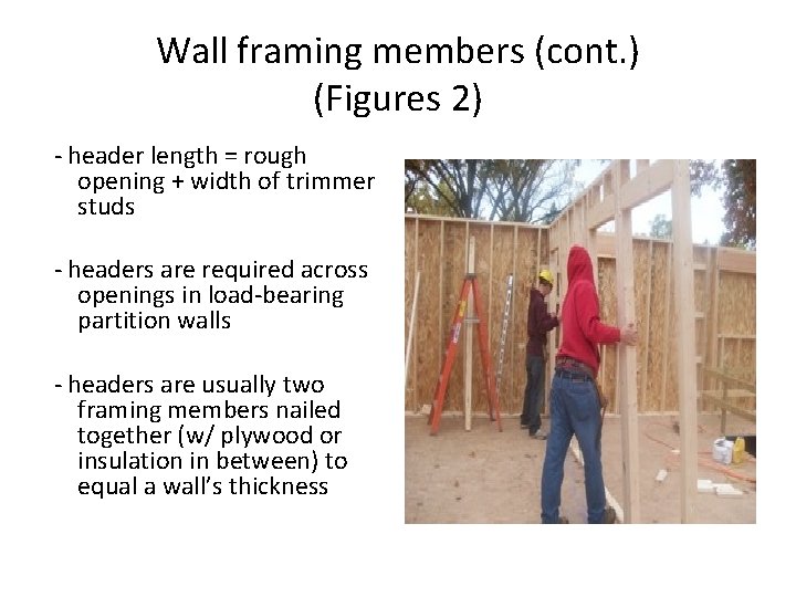
Wall framing members (cont. ) (Figures 2) - header length = rough opening + width of trimmer studs - headers are required across openings in load-bearing partition walls - headers are usually two framing members nailed together (w/ plywood or insulation in between) to equal a wall’s thickness
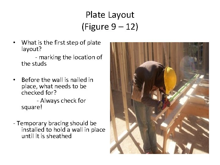
Plate Layout (Figure 9 – 12) • What is the first step of plate layout? - marking the location of the studs • Before the wall is nailed in place, what needs to be checked for? - Always check for square! - Temporary bracing should be installed to hold a wall in place until it is sheathed
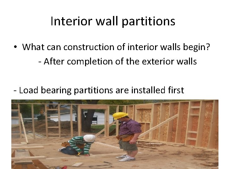
Interior wall partitions • What can construction of interior walls begin? - After completion of the exterior walls - Load bearing partitions are installed first
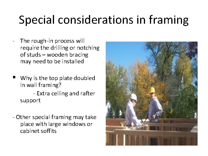
Special considerations in framing - The rough-in process will require the drilling or notching of studs – wooden bracing may need to be installed § Why is the top plate doubled in wall framing? - Extra ceiling and rafter support - Other special framing may take place with large windows or cabinet soffits
Wall sheathing - Should be completed before roof framing begins § What materials are used in the sheathing of exterior walls? - plywood, house wrap, masonry materials - House wrap is designed to cover cracks in wall joints where air may travel through a building
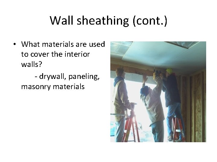
Wall sheathing (cont. ) • What materials are used to cover the interior walls? - drywall, paneling, masonry materials
Partition Intersection • Where partitions meet outside walls, it is essential that they be solidly fastened. This requires extra framing The framing must also be arranged so inside corners provide a nailing surface for wall-covering material. Several methods can be used to tie walls together and provide the nailing surfaces needed. 1. Install extra studs in the outside wall. Attach the partition to them 2. Insert blocking and nailers between the regular studs 3. Use blocking between the regular studs and attach patented back-up clips to support inside wall coverings at the inside corners.
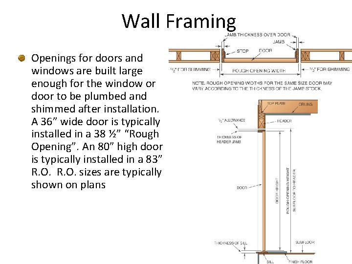
Wall Framing Openings for doors and windows are built large enough for the window or door to be plumbed and shimmed after installation. A 36” wide door is typically installed in a 38 ½” “Rough Opening”. An 80” high door is typically installed in a 83” R. O. sizes are typically shown on plans
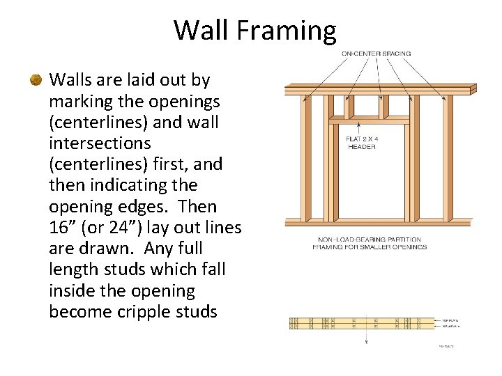
Wall Framing Walls are laid out by marking the openings (centerlines) and wall intersections (centerlines) first, and then indicating the opening edges. Then 16” (or 24”) lay out lines are drawn. Any full length studs which fall inside the opening become cripple studs
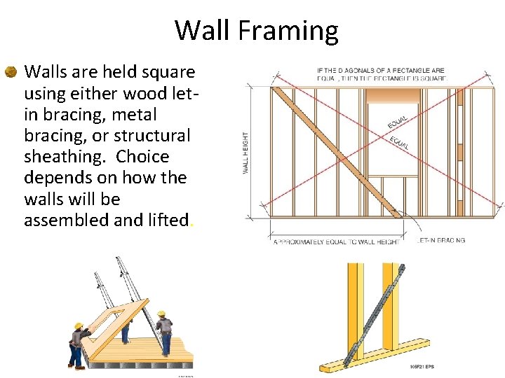
Wall Framing Walls are held square using either wood letin bracing, metal bracing, or structural sheathing. Choice depends on how the walls will be assembled and lifted.
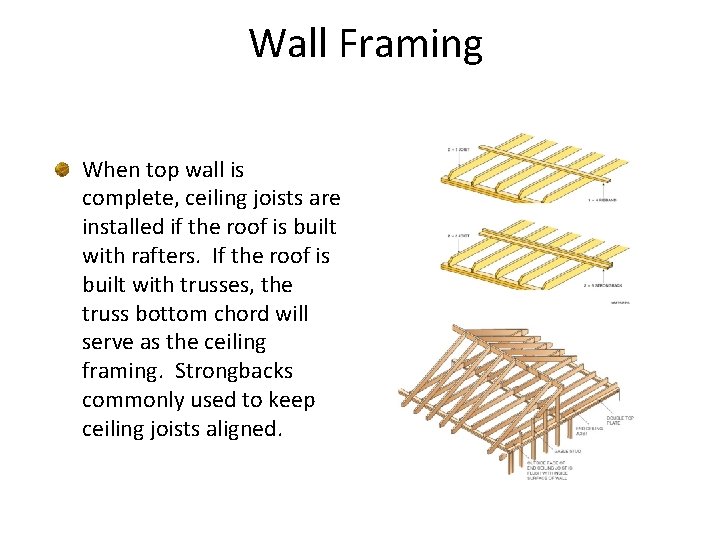
Wall Framing When top wall is complete, ceiling joists are installed if the roof is built with rafters. If the roof is built with trusses, the truss bottom chord will serve as the ceiling framing. Strongbacks commonly used to keep ceiling joists aligned.
Module D 9: Stairs Function of the stairs: Stairs provide access from one floor of a building to another, they are also used for emergency escape Functions: 1. Riser – encloses the space between two consecutive treads in a flight. It also gives support to the tread. 2. Tread – provides a platform for climbing the stair. 3. Headroom – the clear vertical height measured from the ceiling to the nosing of the step which provides unobstructed access from floor to floor. 4. Handrail – provides support to the user when climbing or descending the stair. 5. Balustrade – provides protection to the sides of the stair so persons do not fall off at a height. 6. Newel post – provides support for the handrail and the staircase.
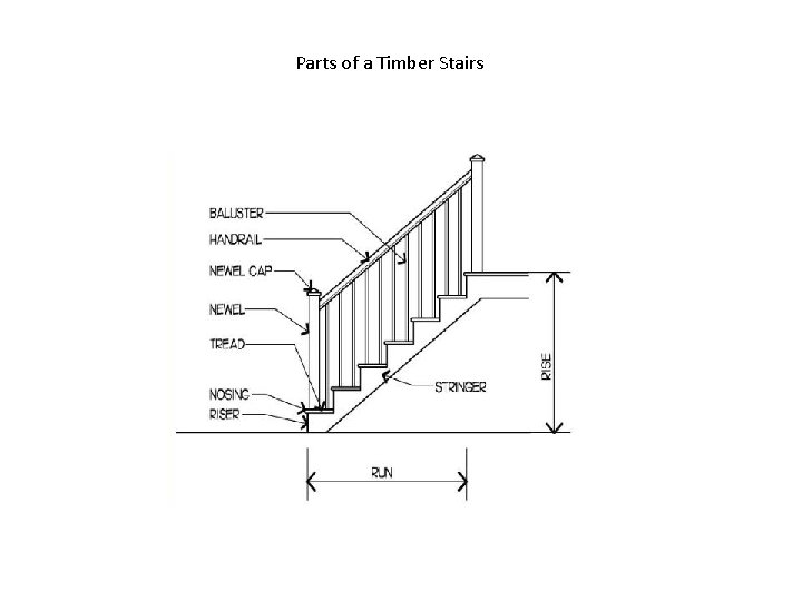
Parts of a Timber Stairs
- Slides: 83