BUILDING SERVICES ENGINEERING EAT 257 Prepared by UMAR

BUILDING SERVICES ENGINEERING EAT 257 Prepared by : UMAR BIN HJ. KASSIM School of Environmental Engineering, Uni. MAP -SEMESTER 2 20010/11.

Content n 1. Type of Air Conditioning Systems- Week 2 n IDENTIFY types of air conditioning system. DISCUSS and ILLUSTRATE three systems are commonly used in the hospitality industry; Window Unit, Split Air Conditioner, Chilled Water System. n 2. Air Conditioning Process- Week 3. n DEFINE and DESCRIBE air conditioning process of treating air to control simultaneously its temperature, humidity, cleanliness (purity) and distribution to meet the requirements of the conditioned space. n DISCUSS air Conditioning design includes air and water, all water systems and unitary equipment. n EXPLAIN and ILLUSTRATE various types of air conditioning and their functions. n 3. Fire Protection- Week 4. n INTRODUCE fire protection systems, n DEFINE and DISCUSS fire classification, portable extinguisher, n ILLUSTRATE fixed fire-fighting installations, fire detectors and alarms, smoke ventilation.

1. Type of Air Conditioning Systems -Week 2. q IDENTIFY types of air conditioning system. q DISCUSS and ILLUSTRATE three systems are commonly used in the hospitality industry: a) Window Unit. b) Split Air Conditioner. c) Chilled Water System.

Air conditioning n DF-Air conditioning and refrigeration are provided through the removal of heat. n The definition of cold is the absence of heat and all air conditioning systems work on this basic principle. n Heat can be removed through the process of radiation, convection, and through a process called the refrigeration cycle. n The using mediums such as water, air, ice, and chemicals referred to as refrigerants.

Air Conditioning n Introduction to Air Conditioning n Air conditioning may be required in buildings which have a high heat gain and as a result a high internal temperature. n The heat gain may be from solar radiation and/or internal gains such as people, lights and business machines. n The diagram below shows some typical heat gains in a room. n http: //www. arca 53. dsl. pipex. com/

Air Conditioning If the inside temperature of a space rises to about 25°C then air conditioning will probably be necessary to maintain comfort levels. This internal temperature (around 25°C) may change depending on some variables such as: · type of building · location of building · duration of high internal temperature · expected comfort conditions. · degree of air movement · percentage saturation

Air Conditioning n In some buildings it may be possible to maintain a comfortable environment with mechanical ventilation but the air change rate will tend to be high (above about 8 air changes per hour) which can in itself cause air distribution problems. n Since air conditioning is both expensive to install and maintain, it is best avoided if possible. n This may possibly be achieved by careful building design and by utilising methods such as: n window blinds or shading methods n heat absorbing glass n heat reflecting glass n openable windows n higher ceilings n smaller windows on south facing facades n alternative lighting schemes.

Air Conditioning n n 1. 2. 3. n n n n n Also the air is cleaned by filters, dehumidified to remove moisture or humidified to add moisture. Air conditioning systems fall into three main categories, and are detailed in the following pages; 1. Central plant systems. 2. Room air conditioning units. 3. Fan coil units. Central plant systems have one central source of conditioned air which is distributed in a network of ductwork. Room air conditioning units are self-contained package units which can be positioned in each room to provide cool air in summer or warm air in winter. Fan coil units are room units and incorporate heat exchangers piped with chilled water and a fan to provide cool air. There are other forms of air conditioning such as; Chilled beams Induction units Variable Air Volume units Dual duct systems Chilled ceiling, but we will consider the more commonly used methods first.

1. 0 Central Plant Systems A typical central plant air conditioning system is shown below. Cooling coil Heater Battery Supply fan Fresh air - Supply air + Room Recirculated air Exhaust air Return air fan Schematic Diagram of Central Plant Air Conditioning System The system shown above resembles a balanced ventilation system with plenum heating but with the addition of a cooling coil.

Central Plant Systems n In winter the heater battery will be on and the cooling coil will probably be n n n n n switched off for the majority of buildings. In summer the heater battery will not need to have the same output and the cooling coil will be switched on. A humidifier may be required to add moisture to the air when it is 'dry'. This is when outdoor air has a low humidity of around 20% to 30%. In the U. K. low humidities are rare and therefore humidification is sometimes not used. In dryer regions humidification is required through most of the year whereas in tropical air conditioning one of the main features of the system is the ability to remove moisture from warm moist air. Dampers are used in air conditioning central plant systems to control the amount of air in each duct. It is common to have 20% fresh air and 80% recirculated air to buildings. In buildings with high occupancy the fresh air quantity should be calculated based on C. I. B. S. E. data. , this may require a higher percentage of fresh air (i. e. more than 20%). See Ventilation section for examples of fresh air rates.

Schematic Diagram of Central Plant Air Conditioning System with Preheater, Dampers, Humidifer and Filters Cooling Coil Supply fan Pre-filter Heater Battery Bag filter(s) Pre-heater Supply air + - Dampers + Room Humidifier Recirculated air Exhaust air Return air fan Schematic Diagram of Central Plant Air Conditioning System with Preheater, Dampers, Humidifer and Filters

n Filters are required to remove particles of dust and general outdoor pollution. n This filter is sometimes called a coarse filter or pre-filter. n A removable fibreglass dust filter is positioned in the fresh air intake duct or in larger installation an oil filled viscous filter may be used. n The secondary filter, after the mix point, is used to remove fine dust particles or other contaminant picked up in the rooms and recirculated back into the plant. A removable bag filter is generally used for this where a series of woven fibre bags are secured to a framework which can be slid out of the ductwork or air handling unit (A. H. U. ) for replacement.
 are")
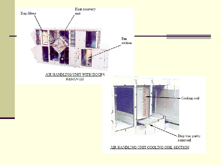
Air Handling Units n n n Air handling units (A. H. U. ) are widely used as a package unit which incorporates all the main plant items as shown below. Pipework, ductwork and electrical connections are made after the unit is set in place on site. Since air conditioning plant rooms tend to be at roof level, the larger A. H. U. 's are lifted into place by crane before the roof is fixed.

AHUn In some cases it is usual to place the fan in front of (that is upstream of) the heater battery and cooling coil. n This is because fans operate best if the system resistance is at the outlet rather than the inlet of the impeller. n This is shown on the schematic diagrams above. n The photograph below shows a typical air handling unit with handles on the doors for access to equipment.

2. 0 Room Air Conditioning Units. Week 3. n These units use refrigerant to transfer cooling effect into rooms. n Room air conditioning units fall into two main categories: n 1. Split type n 2. Window/wall units.

Split Air Conditioners Split air conditioners have two main parts, the outdoor unit is the section which generates the cold refrigerant gas and the indoor unit uses this cold refrigerant to cool the air in a space. The outdoor unit uses a compressor and air cooled condenser to provide cold refrigerant to a cooling coil in the indoor unit. A fan then blows air across the cooling coil and into the room. The indoor unit can either be ceiling mounted (cassette unit), floor mounted or duct type. The drawing below shows a ceiling mounted (cassette unit).

The photographs below show a ceiling mounted cassette and an outdoor unit

Window / Wall Units Window or wall units are more compact than split units since all the plant items are contained in one box. n Window units are installed into an appropriate hole in the window and supported from a metal frame. n Wall units like the one shown below are built into an external wall and contain all the necessary items of equipment to provide cool air in summer and some may even provide heating in winter. n

A small hermetically sealed compressor is used to provide refrigerant gas at the pressure required to operate the refrigeration cycle. n The condenser is used to condense the refrigerant to a liquid which is then reduced in pressure and piped to the cooling coil. n

3. 0 Fan Coil Units n n These are room air conditioners but use chilled water instead of refrigerant. Units can be floor or ceiling mounted. The chilled water is piped to a finned heat exchanger as in a fan convector. A fan blows room air across the heat exchanger and cool air is emitted into the room, as shown below. Outlet louvre Finned pipe heat exchanger Cool Air Chilled water pipes Drip tray and condensate drain Centrifugal fans Dust filter Cabinet Thermostat T Room Air

Fan Coil Units n Fan coil units may be looked upon as being small air handling n n n units located in rooms and they can be piped with chilled water for cooling and low temperature hot water (LTHW) for heating if necessary. The room temperature can be controlled with low, medium and high fan speeds and chilled water flow is varied with a two-port or three-port motorised valve. Two-pipe, three-pipe and four-pipe systems have been used. The four-pipe system has two heating and two cooling pipes and may have a single heat exchanger or two separate heat exchangers for heating and cooling. It is useful to have a summer/winter changeover switch in the main control system to avoid both heat exchangers being on at the same time. A three-pipe system used heating flow, cooling flow and common return pipework.

Fan Coil Units

Choosing an A/C System n Generally central plant systems are used in large prestigious buildings n n n n where a high quality environment is to be achieved. Cassette units and other split systems can be used together with central plant systems to provide a more flexible design. Each system has its own advantages and the following is a summary of some of the main advantages and disadvantages. Central Plant Systems - Advantages: 1. Noise in rooms is usually reduced if plant room is away from occupied spaces. 2. The whole building can be controlled from a central control station. This means that optimum start and stop can be used and a weather compensator can be utilised. Also time clocks can bring air conditioning on and off at appropriate times. 3. Maintenance is centralised in the plant room. Plant is easier to access.

n Central Plant Systems - Disadvantages: n 1. Expensive to install a complete full comfort airn n conditioning system throughout a building. 2. Space is required for plant and to run ductwork both vertically in shafts and horizontally in ceiling spaces. 3. Individual room control is difficult with central plant. Many systems have been tried such as Variable Air Volume (VAV), dual duct systems and zone reheaters. Zone re-heaters are probably more successful than the rest.

n n n n Room Air Conditioning Units - Advantages: 1. Cheaper to install. 2. Individual room control. 3. Works well where rooms have individual requirements. 4. No long runs of ductwork. 5. Can be used to heat as well as cool if a reversing valve is fitted. Room Air Conditioning Units - Disadvantages: 1. Sometimes the indoor unit fan becomes noisy. 2. Noisy compressor in outdoor unit. 3. Each unit or group of units has a filter, compressor and refrigeration pipework that needs periodic maintenance and possible re-charging. Units have course filters therefore filtration is not as good as with AHU’s. 4. The installation may require long runs of refrigerant pipework which, if it leaks into the building, can be difficult to remedy. 5. Not at robust as central plant. 6. The majority of room air conditioners just recirculate air in a room with no fresh air supply although most manufacturers make units with fresh air capability. 7. Cooling output is limited to about 9 k. W maximum per unit; therefore many units would be required to cool rooms with high heat gains.

n n n n Fan coil units are similar is some respects to Room Air Conditioners. Fan Coil Units - Advantages: 1. Cheaper to install than all air central plant system. 2. Individual room control. 3. Works well where rooms have individual requirements. 4. No long runs of ductwork. 5. Can be used to heat as well as cool if 3 or 4 -pipe system is used. Fan Coil Units - Disadvantages: 1. Sometimes the indoor unit fan becomes noisy, especially when the speed is changing with in-built controls. 2. Each unit requires maintenance. 3. Long runs of pipework are required. 4. A chiller is still required to produce chilled water therefore they do not save as much in plant and plant room space as room air conditioners. Also boilers will be required if heating mode is installed. 5. Fresh air facility may not be installed. 6. Cooling output is limited to about 5 k. W.

REFRIGERATION : HEAT TRANSFER CYCLES n Air conditioning system will have these two heat transfer cycles: air cycle and refrigeration cycle. n Two other cycles found in some systems are the chilled water cycle and the cold (cooling water) water cycle. n Understanding the heat transfer cycles will help in the understanding the syllabus air conditioning systems. n There are two air cycles involved in any air-conditioning system i. e. the internal air cycle and the external air cycle.

A. Air Cycle: n - - - n - The internal air cycle involves the conditioning, delivery and the distribution of air in the building. The conditioning of air is the control of the temperature, humidity and quality of air. The delivery of air involves the fan moving the conditioned air and used air through the ducting system. But some system do not have a ducting system and therefore rely on the natural air circulation within the room for air delivery. The distribution of conditioned air involved the local control of temperature and volume of air at the outlet. At the outlet temperature control is possible by using a cooling coil damper and volume control is by regulating the outlet fan. The external air cycle involves the transfer of heat from the air-conditioning system to the outside air. The air-conditioning system releases the heat to the outside air. The heat is dissipated into the larger volume of air. Cooler air is produced and can then goes back to receive heat again from the air – conditioning system.
 n Temperature is controlled using this cycle. - - In Malaysia,")
Refrigeration Cycle (RC) n Temperature is controlled using this cycle. - - In Malaysia, temperature is cooled rather than heated. Cooling is done by having the air pas through a coil of pipes containing cold refrigerant. The refrigerant is a volatile substance and is normally a CFC called Furion 12. At room temperature, Furion 12 is a gas but when under high pressure it becomes a liquid. This characteristic and the principle of latent heat is use in the direct expansion refrigeration process. (Note: As CFC gases are being phased out from use, the type of refrigerant will be a non-CFC gas nowadays) the cycle is as follows:
 n i) Evaporationn In the Evaporator, the cold liquid refrigerant under")
Refrigeration Cycle (RC) n i) Evaporationn In the Evaporator, the cold liquid refrigerant under low pressure absorbs heat from the air cycle thus cooling the air. The refrigerant turns into a low pressure gas due to the absorbed heat. ii) Compression. The low pressure gas is then compressed by the compressor so that the gas now becomes hotter and has high pressure. Because of the high pressure, the boiling point of the refrigerant is increased. Thus the gas refrigerant is carrying excess heat but could not release it due to the insulated pipe.
 n iii) Condensationn The hot high pressure gas passes through the")
Refrigeration Cycle (RC) n iii) Condensationn The hot high pressure gas passes through the condenser. The condenser is a coiled pipe exposed to the out side air. Excess heat and latent heat is transferred to the lower temperature outside air and the gas changes into high pressure liquid at room temperature. iv) Expansion. The pressure of the liquid is lowered after passing through the expansion valve. This causes the lowering of the boiling point of the liquid refrigerant and make it a cold liquid under low pressure. It goes back to step no 1 to continue the cycle.

Cold Water Cycle n In some air conditioning system, the refrigeration cycle transfers the n n n heat to the outside air indirectly. Heat is transferred to the water which flows over the condenser of the heated water is piped and pumped to the cooling tower. In the tower, the heated water is showered so that it comes into contact with the cooler outside air. Heat is transferred from the heated water to the cooler air (see the external air cycle). The air-cooled water is piped back to the condenser to repeat the cycle again. Spraying the water is a good way of releasing heat from the water to the outside air because the water droplets gives a greater surface area for the heat to the escape. But a small portion of the water will also evaporate into the air or will be blown out of the cooling tower. Thus, in order to replace the lost water, this cold water pipe is connected to a replenishing water tank specially meant for the air conditioning system.

Chilled Water Cycle n In some air conditioning system, The RC indirectly cools the air to n n n be conditioned. Chilled water is produced by passing water over the evaporator coil of the refrigerant plant. This chilled water is then piped to the air handling units (AHUs) at various parts of the building. Air from the ducting diverted into the AHU and is cooled by flowing over a coil of piped water containing chilled (very cold) water in the Air Handling Unit (AHU). The heat is transferred from the air to the water. This raises the water temperature and cools the air. The cooled air is then fed into the room via the supply register. The less chilled water pumped back to pass over the Evaporator Coil where the heat is transferred to the RC from the water. Thus the water becomes chilled again. The water flows back to the AHU for air cooling. The Cycle is thus repeated.
 Advantages 1. 2. 3.")
Window Air-Conditioning System Vs Central Air-Conditioning System (Windows a/c system) Advantages 1. 2. 3. 4. 5. 6. Less installation charges. Duct work eliminated. Exact requirement of each room is achieved by individual control. The units are kept running in the rooms only where the cooling is required. Unit of other rooms can be stopped. If one unit fails, air conditioning falls only in one room. Unit of other rooms can be separated individually. Starting with one room, the air conditioning may be progressively extended to other rooms. (Central a/c system) Disadvantages 1. 2. 3. 4. 5. 6. More installation charges. It requires duct system. Exact requirement of each room cannot be met with, since the air is supplied at the same condition to all rooms. Even if one room requires air conditioning, the whole plant is to be operated. Failure of central a/c plant putt off air-conditioning in all rooms. Even for a single room, whole plant should be installed.
 Disadvantages 1. 2. 3.")
Window Air-Conditioning System Vs Central Air-Conditioning System (Windows a/c system) Disadvantages 1. 2. 3. 4. The initial cost and running cost are more per unit of refrigeration. The unit should be kept only in the room to be air-conditioned. The unit is fixed in the room to be conditioned. Hence there will be noise and vibration troubles. Whole unit has to be removed for repair and maintenance. (Central a/c system) Advantages 1. 2. 3. 4. The initial cost and running cost are less per unit of refrigeration. The central plan can be installed quite away from rooms to be air conditioned. The central plan is for away from the room to be air conditioned. Hence there is no noise and vibration problem. Better accessibility for repair and maintenance.

NEW TOPIC …. FIRE FIGHTING

Fire Protection n 3. Fire Protection. n n n INTRODUCE fire protection systems, DEFINE and DISCUSS fire classification, portable extinguisher, ILLUSTRATE fixed fire-fighting installations, fire detectors and alarms, smoke ventilation.

Fire System n The fire systems in a building are many. There are equipment and systems for monitoring, communication, fighting fire, indication, raising alarm, diverting smoke and many others. Generally they can be classified into two categories: n Fire Protection System n Fire Fighting System n Fire systems fall under the fire codes for buildings. As fire codes may vary in different countries, no attempt is made to specify the fire codes. Instead, we will be examining the various components of a fire system in buildings. n Sometimes, there is an overlap of functions - the systems may contain elements of both fire protection and fire fighting.

1. Fire Protection System n Fire protection systems are used to alert people that a small fire or some overheating has occurred, and that there is a danger of fire happening soon. n Smoke detectors, and heat detectors are used to detect such incidents before a big fire occurred. Persons detecting a fire need to sound the alarm to get more assistance. n The break glass is the easiest way to sound the alarm. All the fire alarm panels, sub-control panels, bells, breakglass, smoke detector, heat detectors can be grouped into this area.

Fire Alarm System n The fire alarm system is used to generate alarms whenever there is any occurrence of fire. All the alarm signals can be linked to a central location where humans can carry out activities to handle the fire. There are many designs. The main functions of all these Fire Control designs are: n Indicate fault signals triggered by: n Sprinkler flow switches n Break glasses n Smoke detectors n Heat detectors n Fire pump operation n Air conditioning AHU operation n Smoke spill and ventilation fan operation n CO 2 system operation

Fire Alarm System n n n n Indicate the location or zone of the signal Provide intercom communication from it to each floor Provide public address announcements Acknowledgement of alarm signals Provide a printout of the alarm signal Provide direct alarm signal link to the local Fire Brigade Provide direct telephone communication with the local Fire Brigade A typical Main Fire Alarm system for a high rise commercial center is designed as described below: A fire control room fitted with a Central Processing Unit ( CPU ) and a mimic panel. The panel uses LED to display the location and state of sensors Sixteen (16) Remote Panel Processing Units ( RPPU ), mainly located at the staircases. They collect signals from sensors and also dispatch signals to actuators. The CPU collects incoming signals from all the RPPU and dispatches outgoing signals to actuators through the RPPU All the signals are 24 Volts D. C. The main alarm system is normally operating on AC supply. In case of power supply failure, stand-by batteries are provided for a 72 hours operation The input signals coming from the sensors are the Breakglass, Flow switches, Smoke detectors. The latter are located at the staircases and in the AHU rooms. These signals are collected in the RPPU before being sent to the CPU to indicate a normal status, a line fault, or an alarm. The output signals are sent to the actuators. These can be contactors or motors to stop AHU, lifts, activate roller shutters, alarm bells, pressurization fans, smoke spill fans, and fire dampers. These signals are controlled by the CPU before being dispatched through RPPU to the correct location

Activation of fire alarm n When the fire alarm panel is activated by either breakglass, smoke detector or n n sprinkler flow switch, the following will occur immediately: The printer will print out the exact location and time the event occurred A LED will blink on the mimic panel indicating both the floor concerned and the kind of the sensor responsible for the alarm activation. The fire control room buzzer will start. The CPU will send signals to: n n n Stop the AHU on the floor the alarm occur Start all the smoke spill fans and open the motorized fire dampers on the concerned floor and close those on the other floors Start the Pressurization fans for all the lift lobbies and regulate the pressure in the lift lobbies of the concerned floor using the lift lobby differential pressure device and the associated motorized fire damper. Start the alarm bell continuously for the concerned floor and intermittently for the floor above and below. Close the roller shutters of the concerned floor after three minutes time. Indicate the signals sent on the fire alarm display panel with LED

Acknowledgement of the alarm n A person on duty should then acknowledge the alarm by pressing a push button at the fire control room. The buzzer will then stop but the alarm will still be active. Action needs to be taken to determine whether the fire is real or not. n For a false alarm, the choice will be to isolate the sensor alarm in order to stop all signals and interrupt the fire sequence. n If it is a real fire, the signal will come again after 5 minutes. A general alarm sounds automatically. The CPU will send signals to start the alarm bells continuously for all the floors of the building. The general alarm can also be manually activated through the Manual Evacuate switch.

Fire Intercom System n The fire intercom system is used for communications from several locations to the fire control room. It can be used by the public as well as firemen to give valuable information on the state of a fire. n A typical fire intercom network serves all the staircases from the basement right up to highest floors of a building, the lift motor rooms. Below is some information on how it works: n As soon as somebody picks up the handset in any staircase, the buzzer located at the fire alarm control room will ring. A LED will light up to specify the location of the calling party. Once the operator at the fire alarm control picks up the phone, communication can start. n From the fire alarm control room, calls can also be directed to a specific location in the building using the location address number. The handset at the staircase will then ring. As soon as a person picks up the phone, communication can start.

Fire Fighting System n The fire fighting system will be used when a big fire has already started. There is a need to extinguish it. Sprinkler systems, and hose reel systems are some of the systems used for fire fighting. Wet risers are pipes which distribute large volumes of water to canvas hoses. n The fire fighting systems contain pumps, tanks, and their own distribution piping. Motors or diesel engines drive the pumps. Hose reels and canvas hoses are terminated with nozzles for spray or jet. Sprinkler systems have special glass bulbs and sprinkler rose. Flow switches are installed to cause bells to ring when the sprinkler systems are activated. The systems can also contain gongs activated by water flow. n Automatic CO 2 flooding system will discharge CO 2 gas into electrical rooms to stop any fire.

Fire Fighting System n Portable fire extinguishers are installed at strategic locations so that they can be used to put out small fires. Fire intercom systems are used by fire fighters to communicate with fire control room personnel. n Fire escape doors are indicated with Exit signs, and emergency lights are installed to give a bit of light if the main electrical supply has been cut off. Firemen who have to fight fires will face the danger of electrocution if they use hoses and water. The fireman switch can be switched off to avoid this problem. n Smoke spill fans and exhaust fans are sometimes installed for controlling smoke in a burning building. n In the following pages, we will examine the fire systems in more detail.

Fire Fighting System When a big fire has already started, there is no turning back. The fire has to be put off. n Wet Riser System – n The wet riser system described below is a typical installation in a high-rise building. It is used to supply water from the wet riser water tank, through wet riser pipes, distributed to each floor, and ending at the canvas hoses and hose reels. n The pipes supplying water to the hoses are pressurized all the time. Three pumps supply the water from the tank to the hoses. The pumps are the duty pump, the stand-by pump, and the jockey pump. Pressure switches along the pipe control the starting of each pump. n The wet riser canvas hoses are located at each lift lobby. Each canvas hose has a diameter of 65 mm and a length of 30 m. When the hoses are in use, the pressure at each floor is controlled by landing valves that return excess pressurized water back to the wet riser tank through drain pipes.

Wet Riser System n The hose reels are also located at each lift lobby. Pressure reducers are installed at the end of each wet riser pipe to supply a lower pressured water to hose reels. n When the valves of the hoses are opened, pressurized water will shoot out through the nozzles of the hoses. The pressure in the piping will drop. n The pressure switches at the pump room will sense the drop in pressure and the pumps will start to pressurize the pipe again. A typical system for a highrise building is described below. The pressures are monitored at the pump room to control the pumps.

Wet Riser System n n n n n Jockey Pump The first pump to start will be the jockey pump. The controlling pressure switch is set to start the pump at a pressure of 150 psi and stop it when the pressure reaches 230 psi. If a small leak exist in the wet riser piping - either on the wet riser or hose reel - the pump will start in order to compensate for the leak. Duty Pump If the pressure drops below 125 psi, this means a wet riser landing valve or a hose reel gate valve has been opened. The pressure switch that senses this set pressure activates and starts the duty pump. Stand-by Pump If for any reason the pressure continues to drop below 125 psi, it means either the duty pump has not started or is not available (under repair. . . etc. ). The stand-by pump then takes over the function that is not performed by the duty pump. The stand-by pump is set to cut-in at 95 psi. Once the water flow is not needed any more the pressure builds up in the piping network. The duty or stand-by pumps stops after the cutout pressure is reached at 220 psi. The jockey pump continues to run until the system pressure reaches its cutout pressure of 230 psi. For a low building, the system will be less complicated. However, the purpose of supplying water to the fire fighting hoses is maintained.

Sprinkler System n The sprinkler system is designed to extinguish a fire without human activity. It is especially useful in unattended buildings. The heart of sprinkler system is the sprinkler head. n When there is a fire underneath a sprinkler head, the heat from the fire will cause the glass bulb in the sprinkler head to burst. The glass bulb acts like a plug for the pressurized water in the piping system. Once the glass bulb breaks, the water shoots out from the sprinkler. The sprinkler rose is designed to spread out the water falling over the fire. n As in the wet riser system, the pipes distributing the water is constantly under pressure. A different set of pumps is used to maintain the pressure in the system. The sprinkler pumps are called duty, stand-by, and jockey pumps. Their function is exactly the same as for wet riser pumps. The only difference is in the system they serve.

Sprinkler System n Since the sprinkler system serve unattended areas, it is important that humans can be alerted whenever they are activated. For this purpose, flow switches are installed at each sprinkler zone. Whenever a sprinkler is activated, water flows out from the pipes to the sprinkler head. The flow of the water through a zone pipe activates a flow switch. The electrical signal from the flow switch activates an alarm at the Main Fire Alarm panel. n Each zone is provided with an isolation valve, a flow switch, and a test drain valve. Depending on the size of the building, there may be several water riser pipes supplying to all the floors of a building. Pressure gauges, check valves, and alarm gongs are installed in each riser. The alarm gong is actuated by the flow of water through the check valve and not by electrical signal of the individual sprinkler zones.

Sprinkler System n A typical sprinkler pump installation has the following: n Sprinkler Jockey Pump n If a leak exist in the sprinkler network, the jockey pump starts in order to n n n compensate for the leak. A pressure switch starts the pump at 100 psi, and stops it at 135 psi. Sprinkler Duty Pump If the pressure drops below 75 psi, it means a sprinkler head have been activated, in the building. The duty pump will start. Sprinkler Stand-by Pump If for any reason the pressure continues to drop to 50 psi, it means either the duty pump has not started or is not available (under repair. . . etc. ). The stand-by pump will then start. Stopping of Duty or Stand-by pump Once any sprinkler comes into operation - by bursting of the liquid filled bulbs - the duty or stand-by pump will not stop automatically. There is no cutout pressure for these pumps. They have to be switched off manually. When the running pump has been manually stopped, the jockey pump will continue to build up the pressure in the system until it reaches its cutout pressure of 135 psi.

Fire Brigade System n When a big fire has occurred in a building, the fire brigade has to be called in. It is important that the road is clear for the fire engines to come in. Therefore it is very important for the owner of the building to ensure that the gates, road, and fire brigade devices are not blocked. It is also important that these devices are maintained in good order. n Some of the fire brigade devices are discussed below:

Fire Brigade System n Four-Way Breaching Inlets n A typical high-rise building will have one four-way breaching inlet for sprinkler n n n n tank, and one for the wet riser tank. They are normally installed near the ground floor or lower ground floor, where it is easy for the fire engines to come in. These devices allow the fire brigade to pump water into the tanks in case they have been emptied during fire fighting operations. Street Hydrants Street pillars hydrants are provided as an external source of water besides the fire fighting tanks located in the building. The fire brigade can connect to these pillar hydrants to get additional pressurized water for fighting the building fire. Fireman Switch There a few types of fireman switches. They help to prevent accidents caused by electrical leakage during a fire in a building. When the firefighters use water hoses to shoot or spray on the fire, it is rather dangerous for them when the electrical supply is still live. There is a risk of electrocution. Water can conduct electricity. Visibility is very poor during those times, and the building structures containing electrical wiring may have collapsed.

Fire Brigade System n Some of the fireman switches are discussed below: n Fireman switch for Elevators These switches are enclosed with breakglasses at the lift lobby of the lowest floor. The fire brigade can activate them in order to call back the lift to the lowest floor for emergency purposes. n Fireman switch for Neon Signboards These switches are used to interrupt the power supply to the neon signboard for shops. Neon signboards uses high voltage power supplies. The fire brigade, can activate the fireman switches in order to avoid any additional fire and also to prevent electrocution. n Fireman switch for Electrical Power These switches are used to cut off the electrical power supply to a whole block or floor in the building.

Carbon Dioxide Flooding System n Carbon dioxide is an inert gas used for putting out fire. It does this by displacing the oxygen that is necessary for combustion. Because it is a gas, care must be taken to ensure that fresh air is not allowed to interfere during the process of putting out a fire. Carbon dioxide is particularly useful when dealing with electrical fires. n Carbon dioxide flooding system is used for switch rooms containing high voltages. If there is a fire in these rooms, it is rather dangerous for the firefighters to handle. The rooms will contain live and high voltage electrical supplies. The transformers may contain oil that can burn or explode. n The only sensible thing to do when fighting this type of fire is to close off all the air and displace it with carbon dioxide. With no oxygen available, the fire will eventually die off

Carbon Dioxide Flooding System n Carbon Dioxide Panels n These systems are installed for any room with important electrical or highly inflammable equipment. They are powered by AC mains supply. Stand-by batteries provide 72 hours of operation in case of power interruption. n Each system consists of a control panel connected to one or several heat detectors, smoke detectors, CO 2 cylinders, actuator devices and indicating lights. These panels are located near to the rooms to be protected. Both heat and smoke detectors are installed for such a flooding system. They have to be activated together before the CO 2 will discharge. This is to prevent false signals activating the discharging mechanisms. n The status of any CO 2 panel can be monitored at the Main Fire Control room. n There are two different modes to activate the alarm of the CO 2 panels and subsequent discharge of CO 2 from the cylinders into the room on fire:

Carbon Dioxide Flooding System n Automatic mode Activation of the alarms starts when both the heat and smoke detectors - paired up into 2 zones - have been activated by fire occurring in the protected room. When one detector senses the fire, the alarm bell of the system rings intermittently. Once both types of sensors are activated, the alarm bell becomes continuous. After 20 to 30 seconds a signal is sent to the cylinders plunger-actuating device. The CO 2 is discharged into the room. n Manual mode Activation is made with the breakglass key switch. By turning the key switch, the alarm bell rings, and the CO 2 is discharged immediately. n In rooms that contain ventilation louvers, it is important to seal them off when discharging CO 2 gas. In these cases, the signal for discharging the gas also activates a fire curtain in the room. The curtain above the louver drops down and covers up all of them. n Sometimes the signals may be activated accidentally. All the rooms that are so protected have red and green indication lamps installed above their doors. A room that is filled with CO 2 does not support combustion. Anyone who goes into such a gas-filled room can become unconscious due to lack of oxygen. Whenever gas is discharged, the red lamp above the door will be lighted. Persons must enter only when the green light is on.

ASSIGNMENT-EAT 257 n Questionn Choose one commercial building in Malaysia then analyze how the fire system (fire protection and fire fighting system) operate in that building? * Assignment maximum 5 pages (excluded cover & References). * Submission Dateline 8 February (Tuesday-Before 5. 00 pm) - put in my pigeon hole opposite PPKAS Office. * Assignment Concept- “FIRE PROTECTION”-Depend on your creativity.

THANK YOU
- Slides: 61