Building Code Requirements for Structural Concrete ACI 318
 Analysis and Design for Flexure,")
Building Code Requirements for Structural Concrete (ACI 318 M-11) Analysis and Design for Flexure, Shear, Torsion, and Compression plus Bending David Darwin Vietnam Institute for Building Science and Technology (IBST) Hanoi and Ho Chi Minh City December 12 -16, 2011

This afternoon Analysis and design for Flexure Shear Torsion Compression plus bending

Material properties Concrete higher strengths used for columns Reinforcing steel

Reinforcing bars – 11 sizes: Size No. 10 No. 13 No. 16 No. 19 No. 22 No. 25 No. 29 No. 32 No. 36 Actual diameter 9. 5 mm 12. 7 mm 15. 9 mm 19. 1 mm 22. 2 mm 25. 4 mm 28. 7 mm 32. 2 mm 35. 8 mm Size No. 43 No. 57 Actual diameter 43. 0 mm 57. 3 mm

Flexure Mn Mu

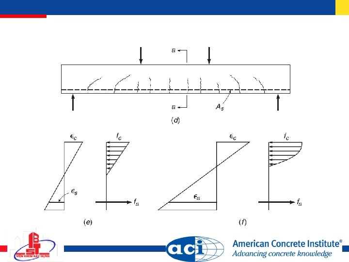

At working loads Cracked transformed section

At ultimate load

Equivalent stress block

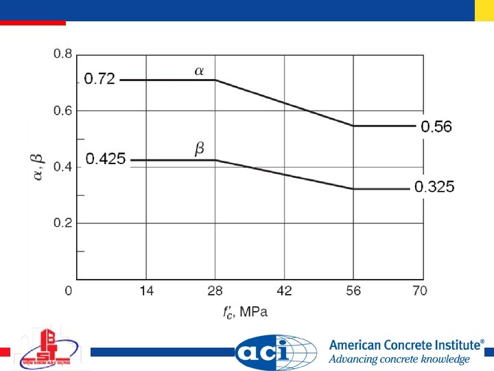
Concrete stress-block parameters

Stress-block parameter 1

Flexural strength = 0. 003

Reinforcement ratio Tension reinforcement Compression reinforcement

Balanced condition and balanced reinforcement ratio, ϵs = ϵy Steel yields just as concrete crushes

Reinforcement ratio corresponding to specified values of steel strain ϵs = ϵt or conservatively

Maximum value of , ϵs = 0. 004

Maximum for a tension-controlled member, ϵs = 0. 005 This is the effective maximum value of
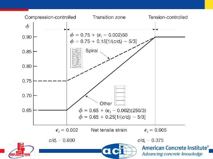

Flexural strength

Minimum reinforcement To ensure that the flexural strength of a reinforced concrete beam is higher than the cracking moment: For statically determinate members with flange in tension, replace bw by smaller of 2 bw or flange width b
 As (required) Slabs and footings As, min")
Exceptions to minimum reinforcement requirements: As (provided) As (required) Slabs and footings As, min = temperature and shrinkage reinforcement

Temperature and shrinkage reinforcement

Cover and spacing
![Doubly reinforced beams [ > 0. 005]](http://slidetodoc.com/presentation_image/6c2da42dacf1a0ef6b8eccb6bda45547/image-26.jpg "Doubly reinforced beams [ > 0. 005]")
Doubly reinforced beams [ > 0. 005]

Doubly reinforced beams Nominal moment capacity for

Doubly reinforced beams Nominal moment capacity for

Doubly reinforced beams Minimum reinforcement ratio so that compression steel yields: If < , c must be calculated (quadratic equation):

Doubly reinforced beams tension-controlled sections

T beams

Effective flange width b Symmetric T beam: b 1/4 span length bw + 16 hf bw + ½ clear distances to next beams Slab on only one side: b bw + 1/12 span length bw + 6 hf bw + ½ clear distance to next beam Isolated T beam: hf ½ bw; b 4 bw

Consider two cases based on neutral axis location Analyze as rectangular beam Analyze as T beam

In practice, use depth of stress block a
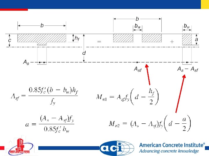

Nominal capacity Limits on reinforcement for tension-controlled section

Flexural crack control

Flexural crack control Maximum spacing s of reinforcement closest tension face fs by analysis or = 2/3 fy

Flexural crack control Distribution of reinforcement when flanges of T beams are in tension: 1. Distribute reinforcement over smaller of effective flange width or width equal to 1/10 span 2. If the effective flange width exceeds 1/10 span, place some longitudinal reinforcement in outer portions of flange

Skin reinforcement required when h > 900 mm

Shear Vn Vu

Diagonal tensile stress in concrete Function of both bending and shear stresses
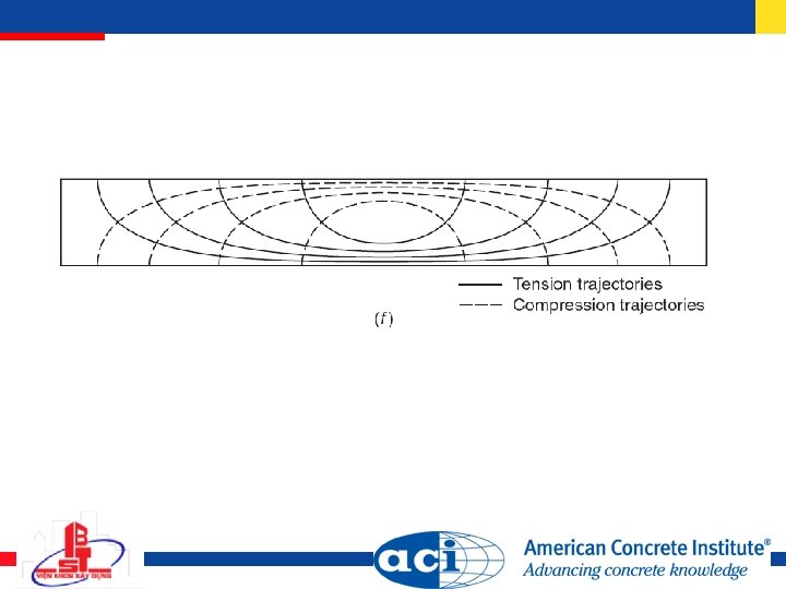

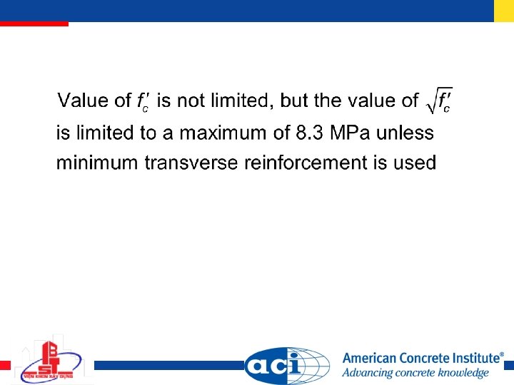
Shear stress at cracking taken as shear strength

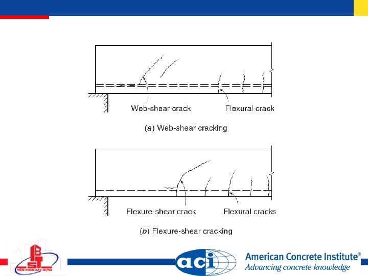
Behavior of diagonally cracked beam

Beams with web reinforcement

Behavior of beams with web reinforcement

Contribution of stirrups

Total shear capacity with Vc may be taken conservatively as

Inclined stirrups
![ACI provisions – summary [Note ]](http://slidetodoc.com/presentation_image/6c2da42dacf1a0ef6b8eccb6bda45547/image-52.jpg "ACI provisions – summary [Note ]")
ACI provisions – summary [Note ]

Lightweight concrete factor = 1. 0 for normalweight concrete = 0. 85 for sand-lightweight concrete = 0. 75 for all-lightweight concrete

Minimum web reinforcement Required when Vu > 0. 5 Vc except for footings and solid slabs; certain hollow-core slabs; concrete joists; beams with h < 250 mm; beams integral with slabs with h < 600 mm, 2. 5 hf, and 0. 5 bw; beams made of steel fiber-reinforced concrete with 40 MPa, h < 600 mm, and
 600 mm")
Maximum stirrup spacing s s d/2 (0. 75 h for prestressed concrete) 600 mm These values are reduced by 50% where
 from")
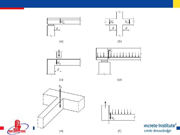
Critical section Maximum Vu for sections closer than d (h/2 for prestressed concrete) from the face of a support may be taken as the value at d (or h/2) provided that three conditions are met: (a) Support reaction introduces compression into the end region (b) Loads applied at or near top of member (c) No concentrated load placed between critical section at d (or h/2) and the face of the support

Stirrup design

Prestressed concrete Vcw Vci

Vc for prestressed concrete dp taken as distance from extreme compressive fiber to centroid of prestressing steel but need not be taken < 0. 8 h for shear design d taken as distance from extreme compressive fiber to centroid of prestressing steel and nonprestressed steel (if any) but need not be taken < 0. 8 h for shear design

Vc = lesser of Vci and Vcw Mmax and Vi computed from load combination of factored superimposed dead and live load causing maximum factored moment at section

Vc = lesser of Vci and Vcw Vd = shear due to unfactored self weight of beam yt = distance from centroid to tension face fpe = compression at tension face due to Pe alone fd = stress due to unfactored beam self weight at extreme fiber of section where tensile stress is cause by external load

fpc = compressive stress at concrete centroid under Pe Vp = vertical component of effective prestress force Pe

Simplified design 11. 3. 4 and 11. 3. 5 address conditions near the ends of pretensioned beams
 Effect of axial loads")
Other provisions (not covered today) Effect of axial loads

Torsion Tu

Equilibrium torsion Compatibility torsion

Compatibility torsion Edge beam: Torsionally stiff Torsionally flexible

Stresses caused by torsion =

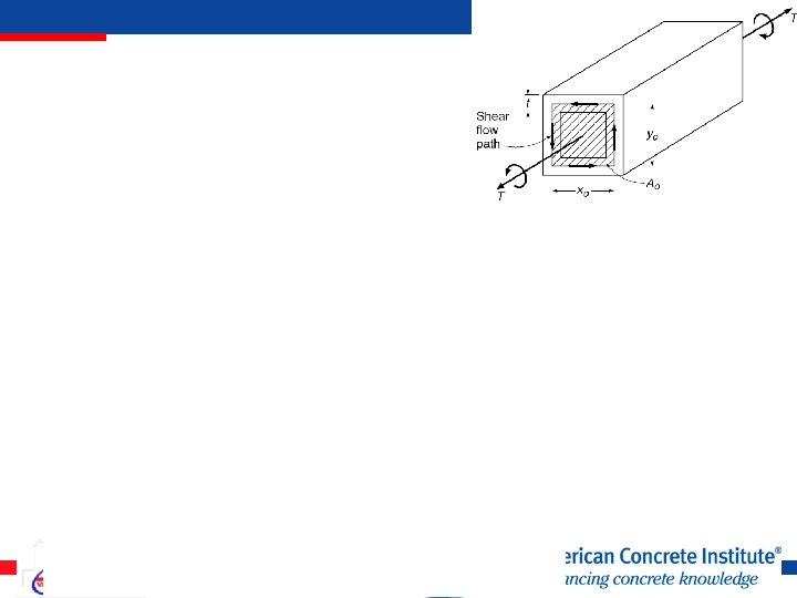
Thin-walled tube under torsion Shear flow q, N/m

q

Torsion in reinforced concrete member Torque vs. twist

After cracking, area enclosed by shear path is defined by xo and yo measured to centerline of outermost closed transverse reinforcement Aoh = xoyo ph = 2(xo + yo)

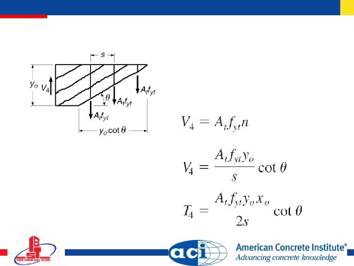
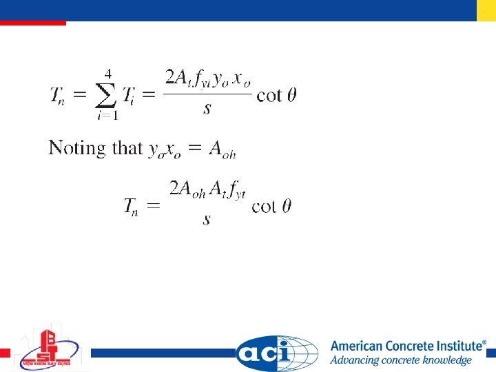
Torque supplied by side 4:

Force in axial direction

Longitudinal steel to resist torsion

Torsion plus shear Hollow section Solid section

ACI provisions = 0. 75 Tu Tn where Ao = 0. 85 Aoh = 30 to 60 , 45 recommended

Minimal torsion Neglect torsional effects if Tu ¼ cracking torque =

Equilibrium vs. Compatibility Torsion For members subjected to compatibility torsion, member is assumed to crack in torsion, reducing its rotational stiffness, and Tu may be reduced to cracking torque = Redistributed bending moments and resulting shears must be used to design adjoining members

Limitations on shear stress Under combined shear and torsion, total shear stress v is limited to

Limitations on shear stress Hollow sections Solid sections

Reinforcement for Shear and Torsion for single leg, fyt 420 MPa Combined shear and torsion

Minimum transverse reinforcement Maximum spacing of transverse reinforcement s ph/8, 300 mm Spacing requirements for shear also apply

Longitudinal reinforcement for torsion Use longitudinal bars at perimeter of section spaced at 300 mm, at every corner of stirrups, and no smaller than No. 10 bar. Must be anchored to develop fy at face of supports.
 Effect of axial loads Some details of hollow sections")
Other provisions (not covered today) Effect of axial loads Some details of hollow sections

Compression plus bending Pn Pu Mn Mu

= 0. 75 for spiral columns = 0. 65 for tied columns
 area of concrete Ast = total")
Theoretical maximum axial capacity Ag = gross (total) area of concrete Ast = total area of steel reinforcement

Maximum axial loads permitted by ACI 318 Spirally reinforced columns Tied columns

Transverse reinforcement - ties At least No. 10 for longitudinal bars up to No. 32 and at least No. 13 for No. 36, 43, and 57 Spacing s along the length of the column 16 diameter of longitudinal bars 48 diameter of tie bars least dimension of column

Transverse reinforcement - ties Every corner and alternate longitudinal bar shall have lateral support provided by the corner of a tie with an included angle 135 degrees and no bar shall be farther than 150 mm clear on each side along the tie from such a laterally supported bar

Transverse reinforcement – ties

Transverse reinforcement – spirals

Transverse reinforcement – spirals Volumetric reinforcing ratio Ag = gross area of column Ach = core area of column – measured to the outside diameter of the spiral fyt = yield strength of spiral reinforcement 700 MPa

Strain compatibility analysis and interaction diagrams Eccentricity e

Example

Example

Interaction diagrams

Balanced failure

Design aids and generalized interaction diagrams e/h

Applying -factors and limits on maximum loads
 Slenderness")
Other provisions (not covered today) Slenderness

Summary Analysis and design for Flexure Shear Torsion Compression plus bending

Tomorrow morning Design of slender columns Design of wall structures High-strength concrete

112

Figures copyright 2010 by Mc. Graw-Hill Companies, Inc. 1221 Avenue of the America New York, NY 10020 USA Duplication authorized for use with this presentation only.

The University of Kansas David Darwin, Ph. D. , P. E. Deane E. Ackers Distinguished Professor Director, Structural Engineering & Materials Laboratory Dept. of Civil, Environmental & Architectural Engineering 2142 Learned Hall Lawrence, Kansas, 66045 -7609 (785) 864 -3827 Fax: (785) 864 -5631 daved@ku. edu
- Slides: 114