Buckling of Columns Buckling Stability Critical Load Introduction

Buckling of Columns Buckling & Stability Critical Load

Introduction n In discussing the analysis and design of various structures in the previous chapters, we had two primary concerns: n the strength of the structure, i. e. its ability to support a specified load without experiencing excessive stresses; n the ability of the structure to support a specified load without undergoing unacceptable deformations.

Introduction n Now we shall be concerned with stability of the structure, n with its ability to support a given load without experiencing a sudden change in its configuration. n Our discussion will relate mainly to columns, n the analysis and design of vertical prismatic members supporting axial loads.

Introduction n Structures may fail in a variety of ways, depending on the : n Type of structure n Conditions of support n Kinds of loads n Material used

Introduction n Failure is prevented by designing structures so that the maximum stresses and maximum displacements remain within tolerable limits. n Strength and stiffness are important factors in design as we have already discussed n Another type of failure is buckling

Critical Load n In looking at columns under this type of loading we are only going to look at three different types of supports: n pin-supported, n doubly built-in and n cantilever.

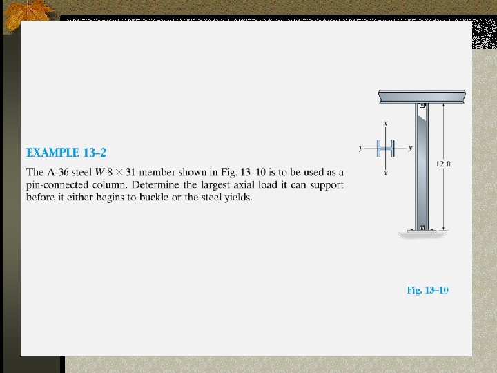
Pin Supported Column n Due to imperfections no column is really straight. n At some critical compressive load it will buckle. n To determine the maximum compressive load (Buckling Load) we assume that buckling has occurred

Pin Supported Column n Looking at the FBD of the top of the beam n Equating moments at the cut end; M(x)=-Pv n Since the deflection of the beam is related with its bending moment distribution

Pin Supported Column n This equation simplifies to: n P/EI is constant. n This expression is in the form of a second order differential equation of the type n Where n The solution of this equation is: n A and B are found using boundary conditions

Pin Supported Column n Boundary Conditions n At x=0, v=0, therefore A=0 n At x=L, v=0, then 0=Bsin( L) n If B=0, no bending moment exists, so the only logical solution is for sin( L)=0 and the only way that can happen is if L=n n Where n=1, 2, 3,

Pin Supported Column n But since n Then we get that buckling load is:

Pin Supported Column n The values of n defines the buckling mode shapes

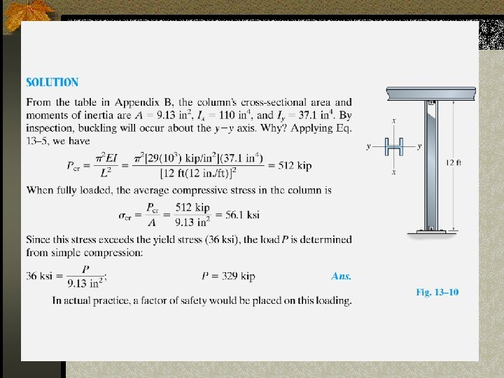
Critical Buckling Load n Since P 1<P 2<P 3, the column buckles at P 1 and never gets to P 2 or P 3 unless bracing is place at the points where v=0 to prevent buckling at lower loads. n The critical load for a pin ended column is then: n Which is called the Euler Buckling Load

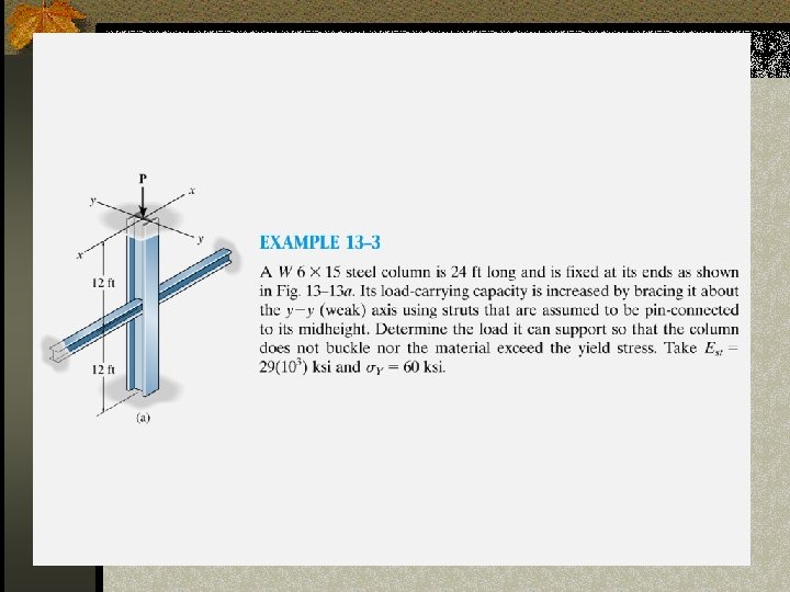
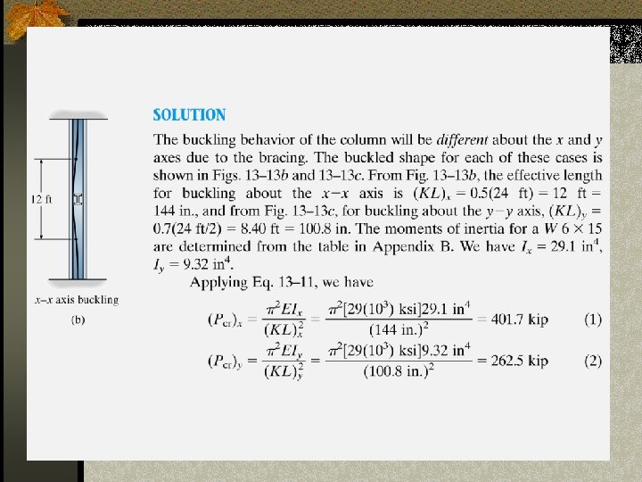
Built-In Column n The critical load for other column can be expressed in terms of the critical buckling load for a pin-ended column. n From symmetry conditions at the point of inflection occurs at ¼ L. n Therefore the middle half of the column can be taken out and treated as a pin-ended column of length LE=L/2 n Yielding:

Cantilever Column n This is similar to the previous case. n The span is equivalent to ½ of the Euler span LE

Therefore:

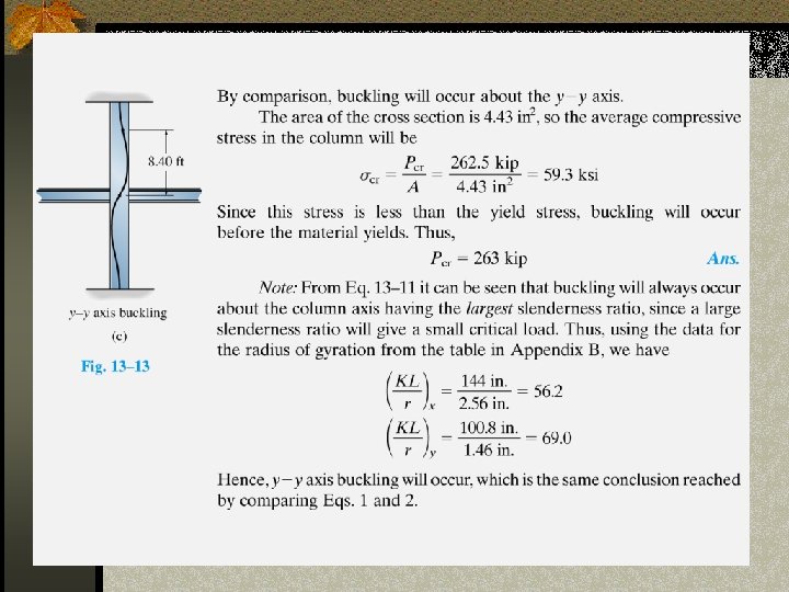
Note on Moment of Inertia n Since Pcrit is proportional to I, the column will buckle in the direction corresponding to the minimum value of I

Critical Column Stress n A column can either fail due to the material yielding, or because the column buckles, it is of interest to the engineer to determine when this point of transition occurs. n Consider the Euler buckling equation

Critical Column Stress n Because of the large deflection caused by buckling, the least moment of inertia I can be expressed as n where: A is the cross sectional area and r is the radius of gyration of the cross sectional area, i. e. . n Note that the smallest radius of gyration of the column, i. e. the least moment of inertia I should be taken in order to find the critical stress.

Critical Column Stress n Dividing the buckling equation by A, gives: n where: n E is the compressive stress in the column and must not exceed the yield stress Y of the material, i. e. E< Y, n L / r is called the slenderness ratio, it is a measure of the column's flexibility.

Critical Buckling Load n Pcrit is the critical or maximum axial load on the column just before it begins to buckle n E youngs modulus of elasticity n I least moment of inertia for the columns cross sectional area. n L unsupported length of the column whose ends are pinned.
- Slides: 26