BU 3102 Construction Technology III Describe the construction

BU 3102 Construction Technology III Describe the construction process of concrete and/or steel piles for deep foundation. Show case studies.
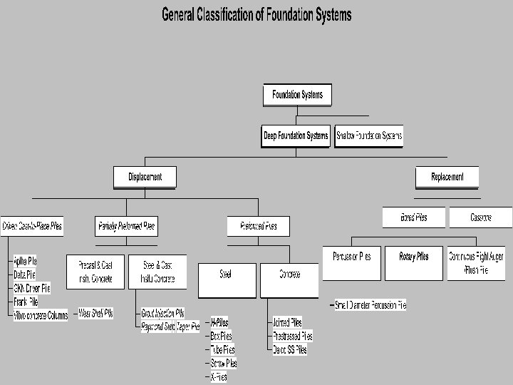
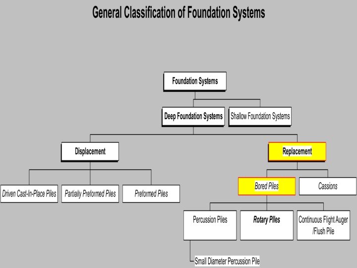

REPLACEMENT PILES

Types of Replacement Piles Percussion Piles v Flush Bored Piles v Rotary Piles v

PERCUSSION PILE

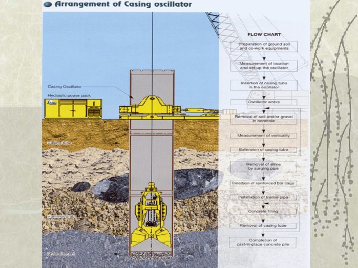
Percussion Piles Method v. Percussive excavation equipment using grabbing method

Percussion Piles Soil Conditions v Coarse gravel and cobbles, glacial till, marls, or thinly bedded shales and clays. A casing oscillator

FLUSH BORED PILE

Flush Bored Piles Method v Continuous flight auger with a length in excess of the borehole depth is drilled into the soil to the required depth before concrete is cast Continuous Flight Auger

ROTARY PILES

Rotary Pile Method v Similar to the construction process in our case study.

v v In some situation, it may be possible to increase the end bearing of the pile by enlarging the base of the pile. This process is known as under reaming.

Closed under-ream tool Opened/working position

CASE STUDY ROTARY PILES
 Location: Tanjong Rhu")
v v Project: Water Place Condominium (three 15 -storey tower blocks) Location: Tanjong Rhu Road Developer: Far East Organization Piling Contractor: WP Piling Co.

Tanjong Rhu Road

Site Overview

Areas to look at: Site conditions and surroundings v Soil investigations v Soil properties v Why bored piling is used v Sequence of piling - Relevant tests carried out in the course of piling v

Site Conditions and Surroundings v v v Reclaimed land, near to waterfront Surroundings: private residential condominium blocks across the road Walking distance to the future Boulevard MRT station

Soil Investigation v Collecting soil samples for testing or/and visual inspection v Sequence of strata v Ground water level

Soil Stratification: Boreholes
 Medium stiff sandy silty clay 10 -20 20")
Soil Properties Soil profile N-value Moisture(%) Medium stiff sandy silty clay 10 -20 20 -40 Soft to firm marine clay (upper) <3 60 -80 Stiff silty clay 20 -30 20 -40 Soft to firm marine clay (lower) <5 40 -60 Dense to very dense clayey sand >100 20 -30 Hard silty clay 60 -80 20 -40

Marine Clay v Kaolinite rich, soft silty clay, with sandy, silty, peaty and shelly fragments

Problems Caused by Marine Clay v Ground heave v Adjacent ground surface subsidence v Negative Skin Friction v v Low bearing capacity and long term settlement High Water Table

Why Bored Piles are Used v v Vibration, noise and dust kept at minimum Soil conditions: Marine Clay - Low bearing capacity: Deeper foundations such as bored piles are needed to reach firm stratum - Ground heave and negative skin friction: Displacement piling not possible - Rough concrete pile surfaces enhance grip against subsoils

Load Transfer: - Bored piles transfer reasonably heavy loads effectively to firm stratum, with larger cross section and combination of concrete (axial load) and reinforcement (lateral load) to take loads. v Site: Spacious for bored pile construction v Can be installed in very long lengths v Cost: cheaper than steel piling v

Sequence of Construction Setting out: 1. The surveyor sets out the exact location the pile. Pegging is done by means timber or metal stick or peg. of of a

Initial Excavation

3. v v v Insertion of metal casing. The casing bypasses the initial sand layers. It serves to guide and align the drilling process.

4. v v The boring operation proceeds. A boring bucket is used to extract wet soils.

v v The boring bucket with a shuttle to drill & extract the marine clay and carry the soft soils to the surface. Slurries formulated with Laviopol Sint P & water mixed in a storage tank are poured into the bored hole.

The mixture of Laviopol Sint P and water is: drilling mud v v v Stabilizes the soil Aid in supporting the sides of the bored hole. Resists water seepage through the sides.

5. v v v Drilling mud is continuously added into the hole during boring. Density, viscosity & p. H checks: to be carried out constantly on the slurries. Ensure correct constituency and mix integrity.

Litmus paper to find p. H value of drilling mud. Apparatus used to measure drilling mud density.

v The end of bored hole reach stiff/hard strata 5 m minimum penetration depth. 6. v The Resident Engineer confirms the depth by lowering a long measuring tape into the hole.

v v v Reinforcement cage is lowered into the hole. Each length of cage is 12 m. Each cage is lowered progressively. Overlapping: 1 - 1. 2 m

v Spacers are installed at random positions around the cage. Spacers are essential to provide sufficient concrete cover all round

v Once all the cages are put in place, its final position is secured by means of a hook bar.

v The tremie pipes with different component lengths are connected and lowered into the hole progressively.

A hopper is connected to the top section, that acts as a funnel. Metal fork to align hopper
 is transported to the site. Prior to")
9. v v v Concrete (Grade 35) is transported to the site. Prior to concreting, some concrete from the truck is taken out & slump test is carried out. Cube test is done as concrete is placed in 3 cubes.

v v Once the delivered concrete passes the slump test, the truck proceeds to the designated bored hole. Concrete is poured into tremie pipe.

v v This concreting method requires the concrete to displace the drilling mud. As the volume of concrete increases at the bottom of the hole, slurries are pushed out of the steel casing. “Washing Effect”

10. v Tremie pipe is hoisted up and down by the crane. v Drilling mud are collected in a nearby earth pit & pumped back into storage water tank for remixing & reuse for the next pile.

v v Drilling mud displaced gets increasingly thicker. Tremie pipe starts moving up from the hole. Crane will draw out part of tremie pipe & its length reduced by removing section by section.

v The steel casing is extracted by means of a vibro hammer. Alternatively, the crane is sufficient to pull out the casing.

15. v Once the concrete is cast, the surveyor/engineer sets up apparatus to check the eccentricity of the cast pile. v The cast pile is eventually back-filled for protection.

DISPLACEMENT PILES
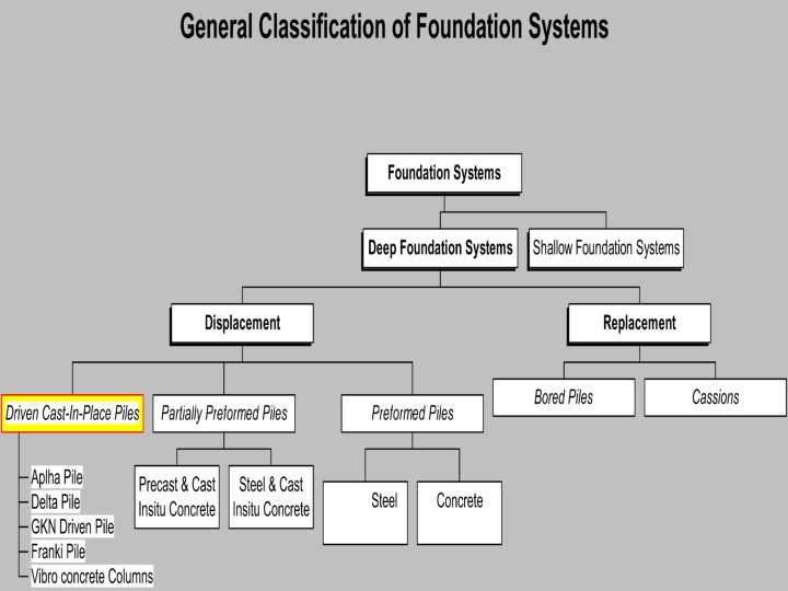

DRIVEN CAST IN-PLACE PILES

Types of Driven Cast In-Place Piles Delta piles v Franki piles v Vibro concrete column v

Delta Pile v Driving with internal mandrel with steel tube with ends closed

Franki Pile v Driving with steel tube with ends closed

Vibro Concrete Column v Poker penetrate soil by vibrating
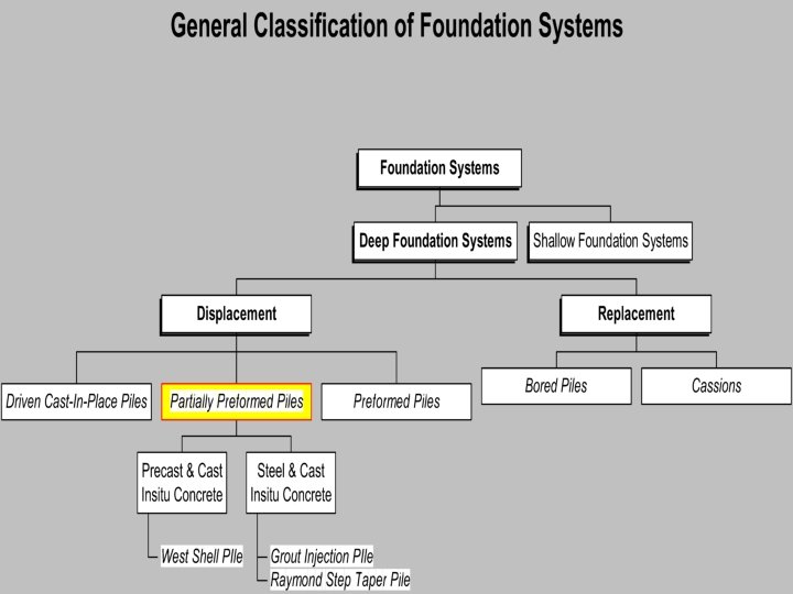

PARTIALLY PREFORMED PILES

Types of Partially Preformed Piles Precast and Cast-In-Situ Concrete v Steel and Cast-In-Situ Concrete v Grout Injection Pile v

Precast and cast-in-situ concrete v A straight-sided steel mandrel, together with precast concrete shells and a concrete conical shoe, are driven into ground by a drop hammer.

Steel and cast-in-situ concrete v v Plain casings are driven by an internal drop hammer. Corrugated casings, together with a mandrel, are driven by a drop hammer.

Western Button Bottom Pile

Grout Injection Pile v v v Drilling. Grout is injected under high pressure via the patented drill tip. After pile is installed, it is filled with reinf. concrete.
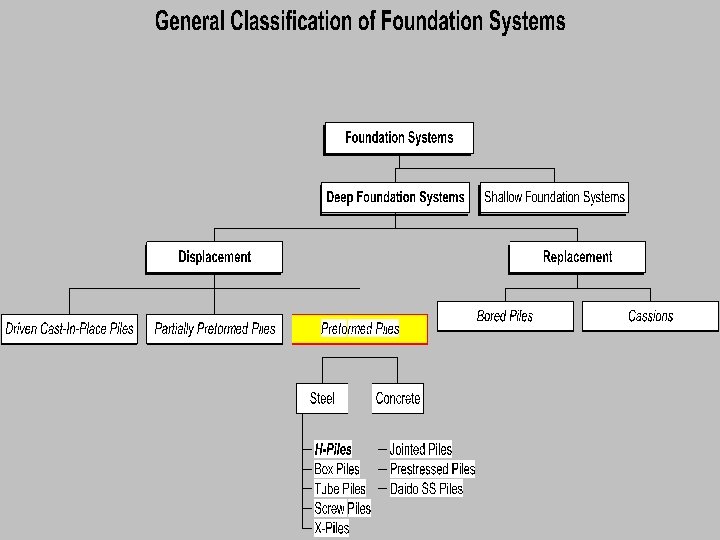

PREFORMED STEEL PILES

Types of Steel Piles H-piles v X-piles v Box piles v Tube piles v Screw piles v

H-Piles v v Rolled steel H sections Small cross-section area

X-piles

Box Piles v May be purpose manufactured or may be formed by welding together longitudinally two standard sheet pile sections, edge-toedge, to form a box

Tube Piles v Steel tube piles can be manufactured in seamless spirally welded, or lap-welded Helical weld

Method The piles are usually installed by hydraulic or drop hammers and driven to refusal

Screw Piles v A circular shaft with helix's welded to the shaft v Screwed into the ground using rotary hydraulics until a sufficiently firm stratum is reached

PREFORMED CONCRETE PILES

Preformed Concrete Piles v v v Driven by powerful impact hammers Square cross-section Reinforcement Special cement Jointed units Prestressed

CASE STUDY PREFORMED STEEL H-PILES

Project Site Contract title

Project Introduction v v Location of site: Ang Mo Kio Ave 9 Usage: 3 Blocks of 16 storeys and 1 of 28 storeys residential buildings v Developer: Housing Board Development v Piling contractor: Antara Koh Pte Ltd v block Brief history: Site once used for older residential flats, which have been demolished

Areas to look at: v Site conditions and adjacent structures v Site and soil investigations v Soil Properties v Why driven-in H-piles are used v Sequence of piling v Relevant tests carried out in the course piling of

Adjacent Site Layout and Site Location The project is of close proximity to: v v Petrol kiosk Residential flats that are half-occupied Main road Car park

Adjacent Site Layout and Site Location Site layout- shows proximity to petrol kiosk and car park

Adjacent Site Layout and Site Location Site layout- shows proximity to residential block 307, 310 and 341.

Soil Conditions and Properties v v Ang Mo Kio is located around the central area of Singapore, thus the soil should be of good and stable properties as it is not made of reclaimed land Relatively good and cohesive firm soil; mainly made of firm clay

Soil Conditions and Properties Soil Investigation From Borehole 1 of 16 Boreholes: 0 m 2 m 4 m Clayey silt Firm silty clay Stiff clayey silt 10 m 13 m 19 m Hard clayey silt with few sand gravels Very dense sandy silt with clay and gravels

Soil Conditions and Properties v v v Very dense clay is encountered at the depth of about 19 meters below ground level. This final level of very dense clay is where the H-steel pile would rest its load upon. Resting on this hard strata ensures the stability and feasibility when steel -piles are used on this site. H

Site and Soil Investigations v v v Borehole – Done prior to piling works. Gives soil investigations results. 16 boreholes were done. Pre-conditioning of neighboring structures – Checks on existing cracks in nearby structures prior to piling works. Structural checks – Checks carried out to see if there is any increment of the cracks as found out earlier in pre -conditioning checks.

Site and Soil Investigations Noise detector : GA 120 Data. Logging SLM

Why Driven-In H-Piles Are Used v Simple process v Time-saving; saves on project time v v Requested by developer Other projects developed by HDB are often using driven-in steel piles, giving HDB the knowledge and experience of working with driven-in piles Available resources such as machinery materials by piling contractor and

Why Driven-In H-Piles Are Used v More accurate in determining correct required length of pile Able to use set value to determine the level where pile reaches hard strata, and thus producing a more effective length of pile

Why Driven-In H-Piles Are Used v v More economic for materials Neighboring residents are few, thus noise and vibration produced does not affect many Soil condition is good and will not cause ground heave nor negative skin friction Able to transfer reasonably heavy loads effectively to firm stratum

v Compacts the soil while driving

Piling Sequence 1. Review piling layout plan. Check type, method and size of the piles stated in the plan. Consists of a range from 2 -pile group to 16 -pile group. 2. Review soil investigation report. The soil type and depth of different soil levels are studied and checked. And the type of hammer to be used is also checked for its feasibility.

Piling Sequence 3. Selection of piling rig and hammer. The specifications of the equipment and hammer will be ascertained to suit the size of H-steel piles to be used as well as the soil condition on site. 4. Material. Checking of the specifications of the materials that are ordered and delivered. The correct size, length and thickness of the piles are to be ordered and delivered.

Piling Sequence 5. Site clearance 6. Prepare platform level

Piling Sequence 7. Surveying and bench marking. Set out the position of each pile and establish the control stations and temporary benchmarks (TMB) on site for the determination of the cut-off level of piles.

Piling Sequence 8. Provide markings to serve as a rough guide to estimate the set during driving.

Piling Sequence 9. Lifting and pitching. Hoist up and place pile into position using wire rope slung over the pile body and lifted using the hoisting crane.

Piling Sequence v Fixing of helmet, followed by driving-in using hammer

Piling Sequence 10. Install mild steel helmet and protect pile head Packing or cushion within with plywood to reduce the noise produced from the hammering and thus keep the noise level low. 11. Driving with a low drop. Check the verticality and position of the leader of the piling rig using a plumb or spirit level and a theodolite. Check on verticality regularly.

Piling Sequence v Initially, pile driven in with a low and slow drop. v Subsequently, hammering proceeds with a higher and faster drop

Piling Sequence 12. Lengthening of piles v v v Chamfering to 45 degrees Use wire brush and made dry Butt weld made

Piling Sequence v Splicing Cool before commencement of driving

Piling Sequence 13. Hammering can stop when the recorded set shows pile penetration is 50 mm or less when under the force of 100 N.

Piling Sequence 14. Kentledge test is used to test the pile.
 test if required. 16. Excavate to")
Piling Sequence 15. Conduct Pile Driving Analyser (PDA) test if required. 16. Excavate to boundary line (up to 4 – 6 metres). And backfill to cover up the Hpiles

Proudly Brought To You By: Tan Kee Chong Richard Tan Kok Kheng Tan Peh Hua Alice Tan Shin Hui Denise Tan Siong Beng Tieo Choo Kheng Toh Chay Boon Christine Wong Hsiao Hwei Yeo Yang Song Ronnie Yeoh Song Nguan Yip Hui Fen Jeannie 994843 N 10 994897 R 10 995006 Y 10 994939 L 10 994845 M 10 994901 E 10 994964 R 10 994920 L 10 994855 J 10 994847 L 10 995001 R 10
- Slides: 105