BU 3102 Construction Technology Discuss testing of piles

BU 3102 Construction Technology Discuss testing of piles with case studies

Introduction There are mainly 2 types of piles v Displacement Piles v Replacement Piles

Problems in Pile Construction v v A specialist activity Problem reduces the performance of the piles Pile load tests to ensure the completed piles are adequately constructed to carry the designed load. If the load tests failed, expensive remedial works have to be done. Hence it is impt for the contractor to be aware of such problems and minimised them.
 l. Steel")
Problems in Pile Construction Driven Piles Design l. Concrete (cracks, handling, joints) l. Steel (driving conditions, stresses) l. Timber (brooming during driving) Installation lpile driving (spalling, boulders, deviations) Associated Ground Movements Heave reduce bearing capacity

Problems in Pile Construction Bored Piles Excavation of Boreholes (Formation of cavities/overbreak, Base of Boreholes, Water in Boreholes) Concreting the piles (quality, placing, extracting casing, design of reinforcement)

Problems in Pile Construction Separation of pile shaft caused by extraction of casing The effect of a large water- filled cavity after extraction of casing

Types of Test Ultimate Load Test piles are tested to confirm design assumptions, and therefore tested to ultimate load. It provides an indication of settlement of a contract pile in isolation and under specified load conditions.

Types of Test Working Load Test This is a test load applied to a selected working pile to confirm that is suitable for the load specified and that it is in conformity with the contract requirements. The test load is normally stipulated to be some multiple of the design load, usually 150%.

Methods of pile testing v Compression Pile Load Test v Uplift Test v Lateral Pile load Test v Integrity Test

Compression Load Test Compression load test is carried out to assess the load carrying capacity of the pile. - It is carried out by simulating the loads - Method selected depends to some extent - on soil conditions - the size of the site - Number of piles to be tested - haulage costs for the kentledge

Uplift test Uplift or pull out test on piles is used to determine the negative skin friction of the soil. - critical where basement or underground - construction is involved can be made at a continuous rate of uplift (CRU), or an incremental loading basis (ML)

Uplift test

Lateral pile load test is to determine the behavior of piles under lateral loading which come from a variety of sources including wind, earthquakes, waves, and ship impacts.

Lateral pile load test A field test carried out to determine the lateral resistance of pile caps.

Lateral pile load test

Integrity testing is a tool in appraising quality of piling carried on site and would ideally reveal the nature and extent of all defects

Load test procedures Maintained Load Test This test is convenient for testing end-bearing piles and for determining the load/settlement characteristics in clay soils Constant Rate of Penetration Test The prime objective of the test is usually to determine the ultimate load capacity the loading is strain-controlled and a set rate of penetration of the pile load is specified Method of Equilibrium This procedure is primarily designed to determine the ultimate load capacity, although it also appears to provide reasonable settlement data

PILE LOAD TEST

Compression load test Kentledge- usually comprises either concrete blocks or pig iron blocks Procedure: - - The test load is applied by means of a hydraulic jack reacting against dead weights known as kentledge incremental load method is employed for the testing of the piles The load at each stage is maintained for a period of one to two hours until the settlement of the pile has substantially ceased or its rate has become negligible The worker then proceeds to start jacking so as to increase load on pile After the addition of the final increment (working load is reached), the test load is left on the pile for about two to three days before the load is released

Compression load test Tension Pile Reaction Systems- are almost invariably specially installed to provide reaction Procedure: - a sufficient number of reaction piles are inserted in the ground with the test pile at the centre connect the piles using test beam(s) with the jack at the centre Jack up the whole arrangement Measure settlement of the test pile Plot time-settlement curve and find out rate of decrease of movement

Tension Pile Reaction Systems One effect of too close spacing between test pile and reaction piles

Tension Pile Reaction Systems

Compression load test Ground Anchor Tension System- Use ground or rock anchors to provide uplift resistance Procedure: - install a sufficient number of anchor piles or suitable anchoring devices so as to provide adequate reactive capacity - test beam of sufficient size and strength is used to avoid excessive deflection under load - Anchor pile test is seldom applied in Singapore due to the popularity of Kentledge pile test

Ground Anchor Tension System Testing rig for compressive test on pile using cable anchors for reaction

Ground Anchor Tension System Example of a multiple ground anchor reaction for raking piles Pile load test set up with steel traps over test beam bolted to anchor piles

Ground Anchor Tension System Two test beams "doubled" with only two anchor piles Two test beams "crisscrossed" using four anchor piles

Methods of Settlement Measurement v Optical methods v Dial gauge extensometers v Stretched wire over a scale v Electrical methods

Methods of Settlement Measurement

Load measurement Load Measurement is preferably carried out using a load cell, and several types are readily available. Commonly adopted load measuring devices are:

Load measurement Hydraulic load capsule Load columns

Load measurement Proving rings Load Cell

INTEGRITY TESTS

Integrity Testing There are basically 9 types of tests that are generally recognized as “integrity tests” and they are as follows: Acoustic tests Radiometric tests Seismic (sonic echo) tests Stress-wave tests Dynamic response tests Electrical tests Excavation Exploratory boring and drilling Closed circuit television methods

Integrity Testing Acoustic tests

Integrity Testing Acoustic tests A display of results for acoustic test (Photograph courtesy of Testconsult Ltd. , Lymm)

Integrity Testing Acoustic tests General arrangement of equipment for twin tube acoustic test (Diagram courtesy of Testconsult Ltd. )
 tests A synthetic pile and the reflectogram")
Integrity Testing Seismic (Sonic echo) tests A synthetic pile and the reflectogram
 tests In the Sonic test, the top of the")
Integrity Testing Seismic (Sonic echo) tests In the Sonic test, the top of the pile is hit with a plastic hammer and the reflected wave is recorded by suitable computerized equipment. From the resulting signal, or reflectogram, one can determine both length and continuity of the pile
 tests Schematic diagram for seismic (sonic echo) tests")
Integrity Testing Seismic (Sonic echo) tests Schematic diagram for seismic (sonic echo) tests
 tests.")
Integrity Testing Seismic (sonic echo) tests.

KENTLEDGE TEST CASE STUDY

Case Study: Kentledge Load Test ü Location: Toa Payoh RC 30 project Toa Payoh Lorong 2 üWorking load test was conducted on 1 number of 1400 mm diameter bored pile (Pile Ref: SLT 2 Blk 147 – G 20/3)

Toa Payoh HDB RC 30

üPurpose : • To proof load the bored pile to 2 times the designed working load, i. e. 1600 tons to verify the working load of bored piles • Working load = 800 tons

Prior to the load test…

üPile head is prepared… • Cut and leveled • Receive a 50 mm thick mild steel plate

Loading Blocks are delivered and stored on site prior to setting up

Kentledge blocks would be supported on a crib work comprising of I-beams

The whole crib is position such that its center of gravity is on the axis of the pile

Bearing pressure under the supporting cribs shall be such as to ensure stability of the kentledge stack Kentledge shall not be carried directly on the pile head


Equipment Used… üHydraulic jack üLoad measuring device üCalibrated pressure gauge Measuring devices are sent to PSB for calibration before start of the test

Hydraulic jack on 50 mm thick steel plate attached to pile head

Pump for jacking up the hydraulic jack

Connection of hydraulic jack to pile head

2 hydraulic load jacks connected to the main beam to deliver an axial load

Pressure gauge indicating the amount of load being jack up


Working Load Test üTest load is loaded according to the loading cycle supplied by the Engineer üPile was jacked up in increments of 25% of the working load at 5 minutes intervals

Maintained for 24 hours at 800 tons Loaded to 1600 tons (2 x working load) and maintained for 72 hours

Working Pile Load Test Loading Cycle
 Load (Tons) Time Interval Remarks 0% WL 0 Setup Initial readings")
Test Load (%) Load (Tons) Time Interval Remarks 0% WL 0 Setup Initial readings 25% WL 200 5 mins Loading 50% WL 400 5 mins Loading 75% WL 600 5 mins Loading 100% WL 800 24 hours Hold 125% WL 1000 5 mins Loading 150% WL 1200 5 mins Loading 175% WL 1400 5 mins Loading 200% WL 1600 72 hours Hold 175% WL 1400 5 mins Unloading 150% WL 1200 5 mins Unloading 125% WL 1000 5 mins Unloading 100% WL 800 5 mins Unloading 75% WL 600 5 mins Unloading 50% WL 400 5 mins Unloading 25% WL 200 5 mins Unloading 0% WL 0 End of Test
 Test Load (%) Load (Tons) Time Interval Remarks Zoom in… 0% WL 0")
(Loading) Test Load (%) Load (Tons) Time Interval Remarks Zoom in… 0% WL 0 Setup Initial readings 25% WL 200 5 mins Loading 50% WL 400 5 mins Loading 75% WL 600 5 mins Loading 100% WL 800 24 hours Hold
 100% WL 800 5 mins Unloading 75% WL 600 5 mins Unloading")
…and (Unloading) 100% WL 800 5 mins Unloading 75% WL 600 5 mins Unloading 50% WL 400 5 mins Unloading 25% WL 200 5 mins Unloading 0% WL 0 End of Test


Monitoring of Settlement…

Level used to take the settlement reading being permanently secured to the ground by mass concrete

Bench mark reference point being permanently secured to ground by mass concrete

2 separate rulers attached to the pile head Obtain settlement readings during loading cycle

Conclusion… Kentledge static load test üMost commonly used method üCost is relatively low compared to other types üEase of setting up üLarge working area

Case Study: Instrumented Piles Introduction v 1. 50 m diameter x 22. 0 m depth v Instrumented with 16 numbers of vibrating wire strain gauges and 2 numbers of tell-tale rod extensometer.

Case Study: Instrumented Piles Objectives l Unit skin friction at ultimate load l Unit end bearing capacity at ultimate load l Stress/strain relationship of the pile/soil subjected to compressive load

Case Study: Instrumented Piles Procedure l Instrumentation 1. 2. 3. 4. l Vibrating wire strain gauges Tell-tale rod extensometer Levelling survey instrument Dial gauges Loading System & Test Program

Case Study: Instrumented Piles Installation of wires into the reinforcement cage

Schematic of the instrumented piles

Case Study: Instrumented Piles Conclusion l Allows more accurate readings to be taken as compare to using optical methods i. e. optical level l Allow the Engineer to observe the pile movements even after the whole building is built up


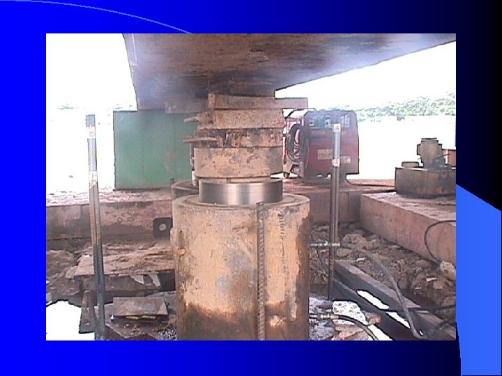
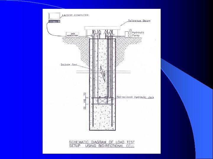
BI-DIRECTIONAL LOAD TEST CASE STUDY

Case Study: Bi-Directional Load Test An alternative method of direct pile static load testing. l The method utilizes a preinstalled high capacity hydraulic jack in the cast-in-place pile loads the pile in two opposite directions (hence bidirectional) at the installed location of the pile l the soil resistance within the pile provides the necessary reaction load, therefore no overhead load frame or external reaction system is required l

Case Study: Bi-Directional Load Test Procedures • Bored pile construction. • Load Test Procedure


Bearing Plates Arrangement
 Holding Time")
Bi-Directional Load Test Program Applied Load (As % of Designed Working Load) Holding Time (hour) 0 20 0. 5 40 0. 5 60 0. 5 80 0. 5 100 0. 5 120 0. 5 140 0. 5 160 0. 5 180 0. 5 200 1. 0 160 0. 5 120 0. 5 80 0. 5 40 0. 5 0

Case Study: Bi-Directional Load Test Conclusion l An alternative method of direct pile static load testing l Cheaper, less time consuming

Acknowledgements - We would like to express our heartfelt thanks to the following people: Dr Michael Chew Civil Department of Housing and Development Board Resident Engineer of Toa Payoh site, Mr Liew Yee Choong Engineer from the piling contractor
- Slides: 87