Broadside Array vs endfire array Assignment Broadside Array

Broadside Array vs end-fire array

Assignment

Broadside Array • Bidirectional Array • Uses Dipoles fed in phase and separated by 1/2 wavelength

Broadside Antenna – A broadside array is a stacked collinear antenna consisting of half-wave dipoles spaced from one another by one-half wavelengths. – This antenna produces a highly directional radiation pattern that is broadside or perpendicular to the plane of the array. – The broadside antenna is bidirectional in radiation, but the radiation pattern has a very narrow beam width and high gain.

UHF-TV Antenna: Yagi with Corner Reflector
 of varying lengths • Phased array")
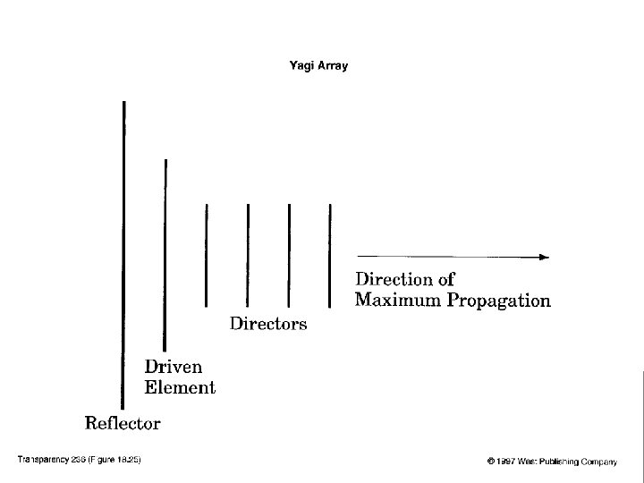
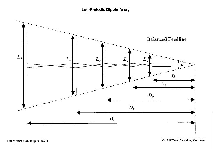
Log-Periodic Dipole Array • Multiple driven elements (dipoles) of varying lengths • Phased array • Unidirectional end-fire • Noted for wide bandwidth • Often used for TV antennas

UHF Yagi with reflector VHF LPDA VHF/UHF TV Antenna

• • Endfire Type of array Broad side type of array

• Endfire with increased directivity
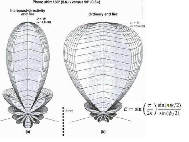

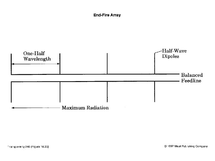
End-Fire Array • Similar to broadside array except dipoles are fed 180 degrees out of phase • Radiation max. off the ends

End-Fire Antenna – The end-fire array uses two half-wave dipoles spaced one-half wavelength apart. – The end-fire array has a bidirectional radiation pattern, but with narrower beam widths and lower gain. – The radiation is in the plane of the driven elements. – A highly unidirectional antenna can be created by careful selection of the optimal number of elements with the appropriately related spacing.

End-fire Arrays • • • Higher directivity. Provide increased directivity in elevation and azimuth planes. Generally used for reception. Impedance match difficulty in high power transmissions. Variants are: – Horizontal Array of Dipoles – RCA Fishborne Antenna – Series Phase Array
 Bidirectional. (b) Unidirectional.")
Figure : End-fire antennas. (a) Bidirectional. (b) Unidirectional.

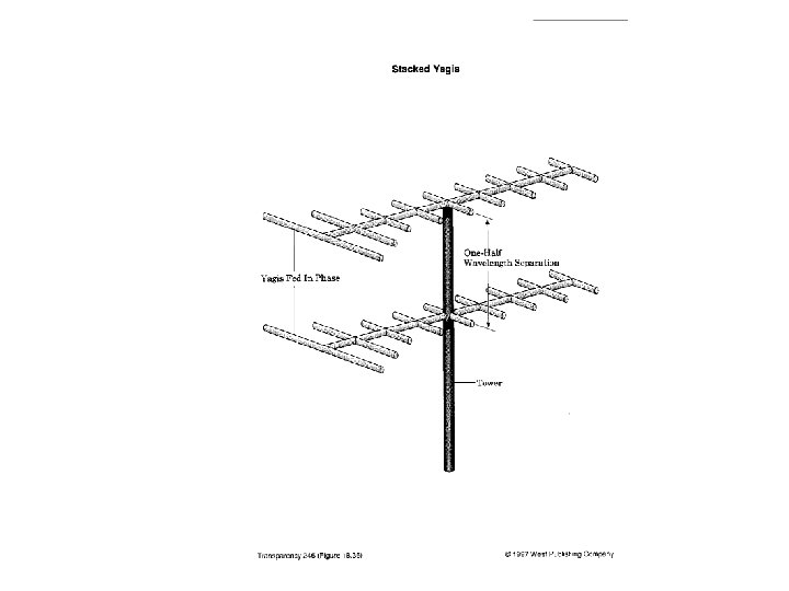
Stacked Yagis • Stacking in-phase Yagis with halfwavelength vertical spacing • Reduces radiation above and below horizon • Increases gain in plane of the antenna

End-Fire Reversing Switch • • Decouples relay power from feedline First transformer inverts signal from east vertical Second transformer converts 37Ω to 75Ω Phasing specs from ON 4 UN’s book
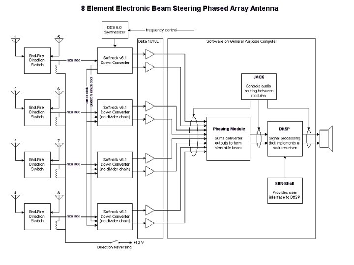

Softrock v 6 Receivers & DDS 6. 0 VFO

Calibration is Annoying • • Softrock input filter very inconsistent Antennas vary despite careful tuning Calibration accommodates inconsistency Use of off-site signal best calibration strategy • In-shack calibration source seems almost good enough

Typical Screen Content

Broadside Arrays Beam steering by phase variation is possible.

Transmission impairments

14 -3: Radio-Wave Propagation Figure : Diffraction causes waves to bend around obstacles.

Circular Arrays

Circular Arrays v Used for direction finding. v Consists of 30 – 100 elements, with equi-spaced and fed from a central source – goniometer. v Band-width seperation is possible:
- Slides: 31