Brightfield Contrasting Techniques Kurt Thorn Nikon Imaging Center

Brightfield Contrasting Techniques Kurt Thorn Nikon Imaging Center University of California, San Francisco USA

Generating contrast in light microscopy • Problem: Many biological specimens are thin and transparent and difficult to see. • Solution: – Fluorescent staining – Brightfield contrasting techniques: DIC, Phase, others Brightfield Phase Contrast DIC

Polarization • Polarization: orientation of E-field. • Most light sources produce unpolarized light – no preferred polarization angle

Polarizers • Polarizers specifically transmit one polarization angle of light • Crossed polarizers transmit no light X

Interference and polarization In phase linearly polarized = + circularly polarized Phase lag = +

Birefringence • Birefringent materials have different indices of refraction for light polarized parallel or perpendicular to the optical axis. • Two beams with orthogonal polarization are produced if illumination is at an angle to optical axis
 DOPL The idea: nm ns Use two beams and interference")
Differential Interference Contrast (DIC) DOPL The idea: nm ns Use two beams and interference to measure the path length difference between adjacent points in the sample

What DIC accomplishes Converts relative differences in optical path length to differences in amplitude

Features of a DIC image 1. Contrast is directional 2. Contrast highlights edges 3. One end brighter, other is dimmer giving a pseudo – 3 D image

Birefringence • Birefringent materials have different indices of refraction for light polarized parallel or perpendicular to the optical axis. • Two beams with orthogonal polarization are produced if illumination is at an angle to optical axis

Wollaston / Nomarski Prisms . f • Two pieces of cemented calcite / quartz • Produce orthogonally polarized beams propagating at different angles • Placed at a back focal plane, this produces the two beams that will probe the OPL difference of our sample
 microscope Camera Imaging path Projection Eyepiece Tube lens Polarizer")
The differential interference contrast (DIC) microscope Camera Imaging path Projection Eyepiece Tube lens Polarizer (analyzer) Wollaston Objective Sample Condenser lens Aperture iris Illumination path Field lens Field iris Collector Light source Wollaston Polarizer

How DIC generates contrast X • Both beams see same OPL • Emerge in phase • Regenerate initial polarization • No light makes it through analyzer

How DIC generates contrast • Beams see different OPL • Right beam is phase retarded • Generate elliptical polarization • Light makes it through analyzer

How DIC generates contrast X • Both beams see same OPL • Emerge in phase • Regenerate initial polarization • No light makes it through analyzer

Role of Bias in DIC

Role of Bias in DIC
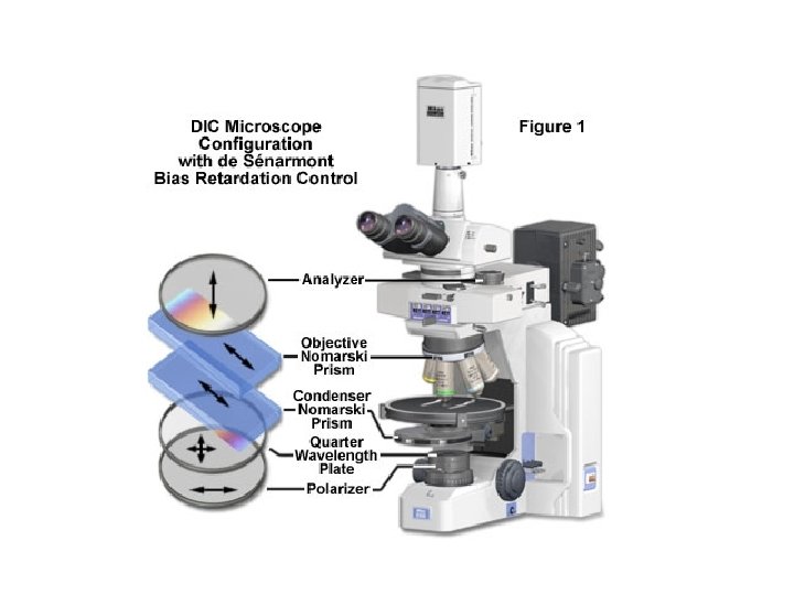

Bias adjusment in de Sénarmont DIC

DIC is sensitive to specimen orientation

DIC doesn’t work on birefringent samples Phase DIC Can’t plate cells on or or cover cells with plastic.

DIC is higher resolution than phase contrast DIC Phase

Combining Phase / DIC with fluorescence To provide cellular or organismal reference. Phase and DIC are more general (and less toxic) than fluorescence. Phase and DIC do degrade fluorescence performance slightly

Bifrefringence in Biological Materials • Anisotropic materials will generally be birefringent • What’s anisotropic in the cell? – Polymers: DNA, actin, microtubules – Membranes

How to detect a birefringent material? • Start with crossed polarizers X • Insert a birefringent material X

Review: The Trans-illumination Microscope Camera Final image plane Secondary pupil plane Imaging path Projection Eyepiece Intermediate image plane Tube lens Back focal plane (pupil) Objective Sample Condenser lens Aperture iris Illumination path Object plane (pupil plane) The aperture iris controls the range of illumination angles Field lens Field iris (image plane) Collector Light source (pupil plane) The field iris controls the illuminated field of view

The Polarized Light Microscope Camera Final image plane Secondary pupil plane Imaging path Projection Eyepiece Intermediate image plane Tube lens Analyzer polarizer Objective Sample Condenser lens Aperture iris Illumination path Field lens Field iris Object plane Polarizer (image plane) Collector Light source (pupil plane)

The Polarized Light Microscope Imaging a normal sample Intermediate image plane Tube lens Analyzer polarizer Objective Sample Object plane Condenser lens Polarizer

The Polarized Light Microscope Imaging a birefringent sample Tube lens Analyzer polarizer Objective Sample e oo e Object plane Condenser lens Polarizer • Bifrefringent sample splits light into e- and orays, which see different refractive indices • The phase retardation of one ray with respect to the other gives rise to elliptically polarized light, which is transmitted by the polarizer

The Polarized Light Microscope Imaging a birefringent sample Tube lens Analyzer polarizer Objective Sample e oo e Object plane Condenser lens Polarizer Birefringent sample is bright on dark background
 for better contrast Tube lens")
The Polarized Light Microscope Add a compensator (wave plate) for better contrast Tube lens Analyzer polarizer Objective Sample e oo e Object plane Condenser lens Compensator Polarizer
 • Uses a circular polarizer analyzer and variable liquid crystal")
Commercial implementation: LC-Polscope (Abrio) • Uses a circular polarizer analyzer and variable liquid crystal retarders to measure orientation independent polarization.

Polarized light microscopy • Good for – Seeing ordered structures in the cell: – Spindles – Other cytoskeletal structures – Membranes – Collagen • No staining required!
 Brightfield Polarization")
Examples – astrocyte (from CRI) Brightfield Polarization

Crane Fly Spermatocytes Rudolf Oldenbourg and James La. Fountain

Further reading www. microscopyu. com micro. magnet. fsu. edu Douglas B. Murphy, “Fundamentals of Light Microscopy and Electronic Imaging” Hecht, “Optics” Slides available: http: //nic. ucsf. edu/dokuwiki/doku. php? id=presentations Acknowledgements Orion Weiner / Mats Gustafsson / Rudolf Oldenbourg
- Slides: 36