Brightfield Contrasting Techniques Kurt Thorn NIC Generating contrast

Brightfield Contrasting Techniques Kurt Thorn NIC

Generating contrast in light microscopy • Problem: Many biological specimens are thin and transparent and difficult to see. • Solution: – Fluorescent staining – Brightfield contrasting techniques: DIC, Phase, others Brightfield Phase Contrast DIC

Review: The Trans-illumination Microscope Camera Final image plane Secondary pupil plane Imaging path Projection Eyepiece Intermediate image plane Tube lens Back focal plane (pupil) Objective Sample Condenser lens Aperture iris Illumination path Object plane (pupil plane) The aperture iris controls the range of illumination angles Field lens Field iris (image plane) Collector Light source (pupil plane) The field iris controls the illuminated field of view

Reminder: Interference In phase constructive interference = + Opposite phase + = destructive interference

Amplitude and Phase Samples Initial beam, unpurturbed Amplitude sample Phase sample

Amplitude and Phase Samples Initial beam, unpurturbed Amplitude sample Phase sample

Many biological samples are phase samples Higher refractive indices slow down light OPL t = sample thickness , ~ 1 micron nm ns ns = sample refractive index , ~ 1. 38 nm = medium refractive index, ~ 1. 33 Optical path length (OPL) difference = t (ns-nm) = 1 micron (1. 38 -1. 33) =. 05 microns = 50 nm, which is about 1/10 the wavelength of green light (488 nm)

Amplitude and Phase Samples Represented as Vector length: amplitude Rotation around circle: phase Only amplitude changes Only phase changes

How can we see a phase change? Problem: optical detectors are not phase sensitive; they only detect changes in amplitude Decompose phase shift into an unpurturbed wave and a perturbed wave
 Perturbed wave")
Converting a phase change to an amplitude change Unpurturbed wave (Surround wave) Perturbed wave (Diffracted wave) Resulting wave (Particle wave) Imagine shifting phase of surround wave by 90° Resulting wave is now reduced in amplitude, and this amplitude change is detectable

Phase contrast microscopy • Need to selectively shift the phase of the surround wave. How to do this? • The sample will scatter light in all directions, so if we illuminate with a small range of angles we can specifically alter the phase at those angles

The phase contrast microscope Camera Final image plane Secondary pupil plane Imaging path Projection Eyepiece Intermediate image plane Tube lens Back focal plane (pupil) Objective Sample Condenser lens Aperture iris Illumination path Object plane (pupil plane) Field lens Field iris (image plane) Collector Light source (pupil plane)

The phase contrast microscope Camera Imaging path Projection Eyepiece Tube lens Objective Sample Condenser lens Aperture iris Illumination path Field lens Field iris Collector Light source Phase contrast objective Selectively retards surround light Illumination phase ring Defines range of illumination angles

Phase Contrast in the Microscope Phase ring is typically built into objective

Phase Contrast – Further Refinements • Typically, phase contrast ring in objective attenuates surround wave by ~75% • Enhances visibility of small phase differences Small amplitude change Large amplitude change

Phase Contrast – Further Refinements • Negative phase contrast – Retards surround wave, so objects which advance phase (low refractive index) are brighter • Positive phase contrast – Advances surround wave, so objects which retard phase (high refractive index) are brighter

Alignment of phase rings Back focal plane Front focal plane

Limitations of Phase Contrast • Halos result from diffracted light that is intercepted by phase ring • Shade off is caused by greater diffraction at edges of objects than their centers

Limitations of Phase Contrast • Poor optical sectioning due to limited illumination aperture. • For sufficiently thick samples, can get more than 360°phase shift, meaning thin and thick regions will be identical in contrast.

Darkfield Microscopy • Idea: throw away all non-diffracted light by illuminating with a condensor annulus at higher NA than the objective. Back focal plane (pupil) Objective Sample Condenser lens Aperture iris Object plane (pupil plane) Field lens • No illumination light makes it through the objective, only diffracted light. Field iris (image plane) Collector Light source (pupil plane)

Darkfield Microscopy • Ideal for small particles, unstained microorganisms, etc. • Can easily see subdiffraction particles (e. g. 40 nm gold) • Not so good for large objects
 DOPL The idea: nm ns Use two beams and interferometry")
Differential Interference Contrast (DIC) DOPL The idea: nm ns Use two beams and interferometry to measure the path length difference between adjacent points in the sample

What DIC accomplishes Converts relative differences in optical path length to differences in amplitude

Features of a DIC image 1. Contrast is directional 2. Contrast highlights edges 3. One end brighter, other is dimmer giving a pseudo – 3 D image

Polarization • Polarization: orientation of E-field. • Most light sources produce unpolarized light – no preferred polarization angle

Polarizers • Polarizers specifically transmit one polarization angle of light • Crossed polarizers transmit no light X

Interference and polarization In phase linearly polarized = + circularly polarized Phase lag = +

Birefringence • Birefringent materials have different indices of refraction for light polarized parallel or perpendicular to the optical axis. • For unpolarized light two beams with orthogonal polarization are produced illuminated not along optical axis

Wollaston / Nomarski Prisms . 1 f • Two pieces of cemented calcite / quartz • Produce orthogonally polarized beams propagating at different angles • Placed at a back focal plane, this produces the two beams that will probe the OPL difference of our sample
 microscope Camera Imaging path Projection Eyepiece Tube lens Polarizer")
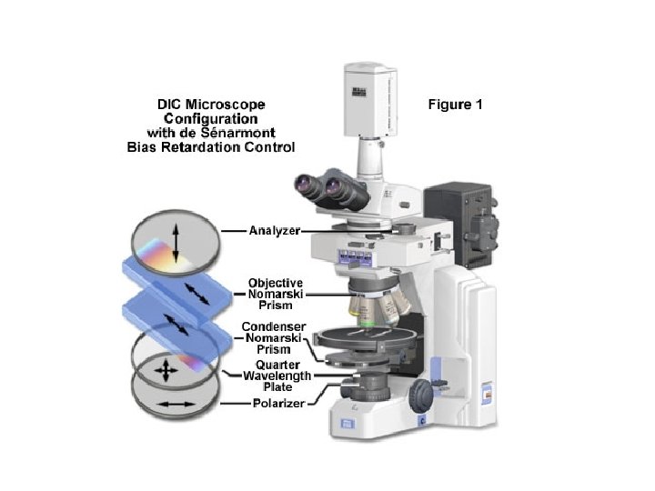
The differential interference contrast (DIC) microscope Camera Imaging path Projection Eyepiece Tube lens Polarizer (analyzer) Wollaston Objective Sample Condenser lens Aperture iris Illumination path Field lens Field iris Collector Light source Wollaston Polarizer

How DIC generates contrast X • Both beams see same OPL • Emerge in phase • Regenerate initial polarization • No light makes it through analyzer

How DIC generates contrast • Beams see different OPL • Right beams is phase retarded • Generate elliptical polarization • Light makes it through analyzer

How DIC generates contrast X • Both beams see same OPL • Emerge in phase • Regenerate initial polarization • No light makes it through analyzer

Role of Bias in DIC

Role of Bias in DIC

Bias adjusment in de Sénarmont DIC

DIC is sensitive to specimen orientation

DIC doesn’t work on birefringent samples Phase DIC Can’t plate cells on or or cover cells with plastic.

DIC is higher resolution than phase contrast DIC Phase

Combining Phase / DIC with fluorescence To provide cellular or organismal reference. Phase and DIC are more general (and less toxic) than fluorescence. Phase and DIC do degrade fluorescence performance slightly

Further reading www. microscopyu. com micro. magnet. fsu. edu Douglas B. Murphy, “Fundamentals of Light Microscopy and Electronic Imaging” Hecht, “Optics” Acknowledgements Orion Weiner / Mats Gustafsson
- Slides: 42