Brief introduction to Crystal Channeling and its application

Brief introduction to Crystal Channeling and its application to beam collimation (not intend to cover all of the topics) Shilun Pei April 16, 2008 Many thanks to the following two references: 1) V. M. Biryukov et al. Crystal Channeling and Its Application at High-Energy Accelerators. Springer, 1997 2) Said Hasan. Bent Silicon Crystals for the LHC Collimation: Studies with an Ultrarelativistic Proton Beam. Master Thesis, 2007

Overview • History of crystal channeling • Crystal channeling – – Channeling in straight crystal Particle motion in bent crystal Volume capture in bent crystal Volume reflection in bent crystal • Channeling application to beam collimation • Conclusion

History of crystal channeling • First suggested by Stark in 1912 —> motion of particle can be confined in crystal region called channels • Overshadowed until early 1960 s —> computer simulations and experiments revealed anomalously long ion ranges in crystals • Theoretical explanation of the channeling effect by Lindhard in 1960 s • Before 1974, investigations into the channeling restricted in low energy charged particles • 1974, extended to high energy regions, experiments started at CERN around the time the SPS was built • 1976, Tsyganov proposed to use bent crystal to deflect high energy particle beam, confirmed in 1979 at FNAL in Batavia • In the following years, new interesting effects (volume capture and volume reflection) were found. Due to the high deflection efficiency of volume reflection effects, it is a good alternative for beam collimation application.

What is crystal channeling? • Amorphous material or misaligned crystal – Number of collisions with different impact parameters – Variety of processes (Rutherford scattering, γ-ray emission, ionization, X-ray production, etc. ) – Collisions uncorrelated, yield of processes independent from target orientation • Mono-crystal target —> Scenario changes – Can be confined in the space between the crystalline planes or axes —> channeling – Can leave the channel after gaining enough transversal momentum —> dechanneling

Why crystal channeling? Atoms non-ordered Atoms arranged in planes Atoms arranged in strings

Cubic lattice system Orientation of the most important crystallographic planes and axes in the cubic lattice system 1] [110] [1 00 ]

Crystals of the diamond group • Most crystals for channeling investigation are made of silicon <— development status of semiconductor tech • Diamond group characterized by covalent bond • Each atom linked with 4 neighbors —> tetrahedron Diamond cubic lattice Two identical face centered cubic lattices pushed one into another and shift along the buck diagonal by one quarter of its length
 Whole plane continuum approximation")
Interplanar potential for Si channel One atom Si channel (110) Whole plane continuum approximation Si channel (111)

Thermal vibrations & harmonic model Quantum mechanics of harmonic oscillator model Potential generated by Si channel (110) From to bottom the lines correspond to T=0 K (static), 77 K, 300 K and 500 K Heavy particles (protons & ions), always right. Light particles (e+, e-), starts to work in 10 -100 Me. V range.

Particle motion in the channel Pt<U 0 θ=Pt/Pl θ<<1 Dechanneled particles Simulated phase trajectories of 450 Ge. V/c protons on the plane (x, θ) in Si(111) for a straight crystal Channeled particles

Condition for channeling Generally, Umax is reached at x=dp/2, while due to nuclei scattering just below dp/2 and thermal vibration, Umax=U(xc), where xc is the critical transverse coordinate, xc=dp/2 -a. TF-2. 5 u. T. For high energy particles, xc=dp/2 -a. TF-u. T due to reduced scattering. Critical angle θc is the maximum incidence angle available for channeling. For silicon crystal, Umax is 20 e. V, θc is 280μrad at 500 Me. V, 9. 42μrad at 450 Ge. V, 2. 39 μrad at 3 Te. V. Crystal acceptance is defined as the particles fraction striking the crystal that can channel. Above formula is for straight crystal and a uniform beam with 2Φ≥θc. When scattering (dechanneling) can be neglected (for thin crystal and thin crystal), it equals to the channeling efficiency.

When the transverse energy of particle in the crystal channel is conserved, we can get the particle trajectory with harmonic model. For 450 Ge. V/c proton, λ~27μm.
 • In real crystals, due to scattering processes, the")
Dechanneling (valid for positive particles) • In real crystals, due to scattering processes, the difference of the real potential and the continuum potential approximation and the crystal defects, the particle’s transverse energy is not exactly conserved. • The transverse energy can grow and overcome the potential well causing the particles exit from the channel. This process is called dechanneling. • On the contrary, particles can go through the crystal plane and lose transverse energy and finally be trapped. This process is called feed in.

• Dechanneling length LD – Indication of particle tendency to remain in channeling • Reduction of channeled particle along crystal depth – N=N 0 e-L/LD – dp (I is the ionization potential, for silicon it is ~172 e. V, me is the electron rest mass, re the classical electron radius, Zi is the charge number of the particle) – LD∝pv (scatting effects reduced)& LD∝dp • Above is for soft scattering, can be described by diffusion formalism, since θs<<θc, and the angle is changed by frequent infinitesimal steps. • In Me. V range, (M is the particle mass) is smaller than the critical angle θc. For example, in silicon for proton energies up to 10 Me. V, while θ >1 mrad.

• In energy range ~100 Ge. V, θc~10μrad, θs>θc might happen, the particle is thrown outside the channel and this event is called hard scattering and can’t be described by the diffusion formalism. • Single scattering characteristic length • Contribution of hard scattering is smaller than the soft scattering.

Axial channeling • Particle moving at a small angle relative the crystal atomic strings feels electric field generated by string atoms as if by a charge distribution with cylindrical symmetry. This is called axial channeling. Potential of isolated string Si (111) Si (110) Si (100)

Energy loss • Energy loss of ionization for channeled particles is suppressed because they are confined in a region with small electron density. Solid: n Dashed: d. E Energy loss spectrum in germanium Planar channeling Axial channeling
, energy irradiated is more intense than")
• For light particle (e+ & e-), energy irradiated is more intense than standard bremstrahlung one and has a peculiar peaked structure. – Misaligned crystal —> incoherent bremstrahlung – Aligned crystal —> coherent bremstrahlung (particle not in channeling) & channeling radiation (channeling, used to increase positron production) – Sensitivity to charge sign Positron Electron Photo energy spectra for 10 Ge. V/c particle impinging on Si(110) plane (0. 1 mm thickness)

Bent crystals • Suggested by Tsyganov in 1976 to steer a high energy particle with a bent crystal. The bending of the crystallographic planes can produce a curved channel to deflect the channeled particle. • Bent crystal revealed two new effects: volume capture and volume reflection. w Example of a bending device Bent crystal working principle Note: • For practical mechanical reasons, R>>w. • Crystal length L is independent from the radial coordinate r.
 Lab inertial frame (Initial 0 pt, while during")
Particle motion in bent crystal a) Lab inertial frame (Initial 0 pt, while during the motion particle has an angle wrt curved crystal plane —> new equilibrium position) b) Non inertial frame which rotates with the particle (constant p, particle doesn’t change direction —> centrifugal force appears)
 planes interplanar potential: straight crystal (solid line), pv/R=1 Ge.")
Effective interplanar potential Si (110) planes interplanar potential: straight crystal (solid line), pv/R=1 Ge. V/cm (dashed line) and pv/R=2 Ge. V/cm (dotted line) Centrifugal force pushes the particles toward the atomic plane (dechanneling), when Critical curvature radius

Harmonic approximation Potential barrier Critical angle Particle trajectory Same oscillation period as straight crystal, but new equilibrium point Dechanneling length No more linear function of pv as in straight crystal

Volume capture Incidence angle θ is relatively small Feed-in probability rapidly decreases since particle no more aligned with the crystal during the motion When θ increases, particle maybe aligned with the crystal within the crystal volume due to transverse energy decrease (scattering)—> volume capture Volume capture probability

Volume reflection • Volume reflection – particle deviation in a single point inside the crystal due to elastic scattering with the atomic potential barrier. First considered in computer simulations and recently observed. Reflection angle

xb<x<dp/2, rt=ndp+x Schematic of the effective potential at the turning point Reflection angle Effective potential of smaller radius, ΔU(x) increases, Δθr increases xb<x<dp/2 Assuming R>>Rc, and particle enters and leaves the crystal in the center of the channel (both favor large reflection), contribution of centrifugal force to Ueff is very small, then we can get the approximated reflection angle

Strongly asymmetric, multiple scattering before and after reflection is not considered.
 Silicon crystal")
Simulated angular distributions of 400 Ge. V protons scattered by a (110) Silicon crystal (curvature radius 10 m): plot 1 without the multiple scattering contribution, plot 2 taking it into account; b) the same plot in a larger horizontal (angular) scale; the right tail of the distribution shows the volume captured particles.

Volume reflection vs channeling • Large acceptance – Channeling angular acceptance θc is fixed, deflection efficiency is limited; volume reflection acceptance equals to the bending angle, larger and can be adjusted. • High energy favor – Scaling properties of volume reflection: θr∝E-1/2 – Scaling properties of multiple scattering: θms∝E-1 – Scaling properties of channeling: θch∝E-1 • High efficiency – All of the non-volume captured particles can be reflected, since volume capture probability ∝E-3/2, very high efficiency (~100%) is expected for high energy reflection. Good alternative for beam collimation

First volume reflection observation IHEP U-70 accelerator in Protvino • Lcrystal=0. 72 mm, Acrystal=20 x 60 mm 2 • θb=423μrad, θc=24μrad, θms=13. 5μrad • θr=39. 5± 2. 0 μrad=(1. 65± 0. 08) θc

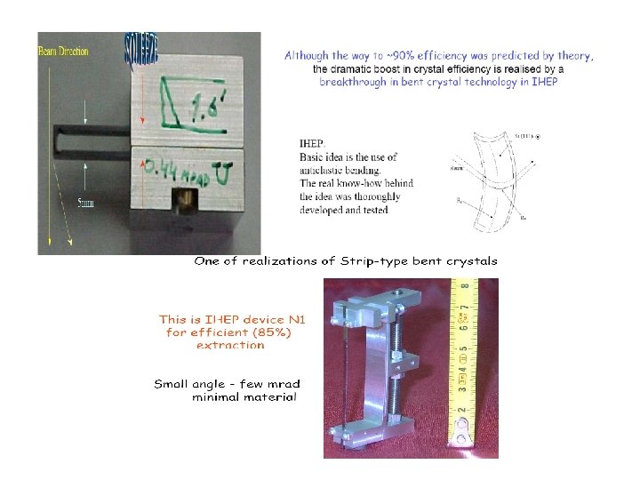
Bent crystal applications • Crystal assisted beam extraction – A. G. Afonin, et al. NIM B, 234: 14 -22, 2005 • Focus beam – A. S. Denisov, et al. NIM B, 69: 382, 1992 • Split beam – A. Baurichter, et al. NIM B, 27: 164 -165, 2000 • Crystal undulators – A. S. Bellucci, et al. PRL, 90: 034801, 2003 • Measure magnetic moments of shortlived particle – V. V. Baublis, et al. NIM B, 90: 112, 1994 • Halo collimation – M. A. Maslov, et al. The SSC beam scrapter system. SSCL, 484, 1991

History of crystal collimation • 1979 FNAL, deflected beam fraction 1% • 1996 CERN SPS, 120 Ge. V beam extracted, 20% • Multi-pass extraction can increase the final efficiency Efficiency measured at SPS as function of beam momentum
 Multi-pass extraction • Extraction efficiency is defined as the ratio of")
IHEP experiments (1997~) Multi-pass extraction • Extraction efficiency is defined as the ratio of extracted beam intensity to the beam loss in the entire ring.
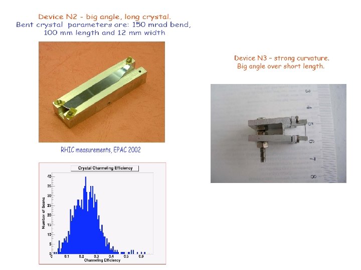

RHIC experiments
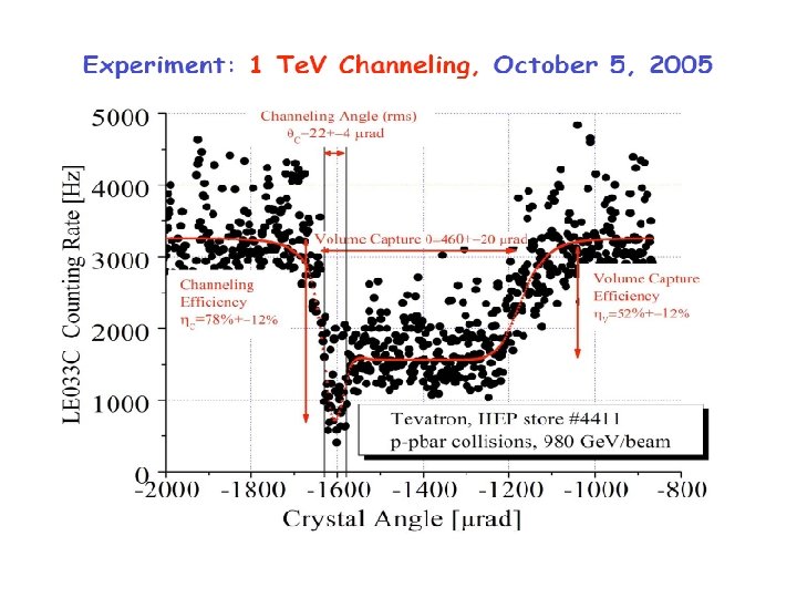

Tevatron experiments θb=440μrad The whole arc effect First interpreted by volume capture due to absent of detecting system able to recognize particle trajectory. While due to the volume capture probability is very low in bent crystal, further clarify is needed.

Volume reflection was further clarified in Montecarlo simulation

LHC crystal collimation • Three collimation possibilities: – Single-pass channeling ~ suppress 2 nd turn channeling, low efficiency – Multi-pass channeling ~optimized to have high efficiency – Single-pass volume reflection ~100%

Several considerations favor volume reflection and using short crystal however provides smaller angular reflection • High single-pass deflection efficiency. • Large angular acceptance. • Due to large acceptance, volume reflection (even multiple reflection) alignment tolerance can be greatly relaxed than channeling and conventional collimation. • The smaller angular volume reflection angle (θr~1. 5θc~1020μrad) can be solved by multiple volume reflections.

Radiation damage experiment Lifetime of crystal can be 10 s years

Recent experiments on volume reflection See last week’s talk

Multi-crystal reflection Same alignment Different alignment

Conclusion • Crystals can be very efficient in accelerators, make accelerator 10 times cleaner. • Crystals can work at high intensities environment with many years lifetime. • Currently, most simulations and experiments on crystal collimation are focused on heavy positive particles, light particles (e+ & e-) rarely seen.
- Slides: 44