BRIDGE RULES PURPOSE Specifies the rulesloads for Design

BRIDGE RULES

PURPOSE Specifies the rules/loads for Design of superstructure & substructure of Bridges Assessing the strength of existing Bridges Any Revision/addition/alteration shall be through correction slip only, no cognizance to be given to any policy directives issued through other means

SCOPE Loads specified shall be used for All Railway Bridges Turn Table girders Foot Bridges but excluding Road Bridges Design detailing shall be controlled by appropriate code of practice Road Bridges shall be as per IRC codes

LOADS Loads specified in Bridge Rules : Dead Loads Live Loads Dynamic effects Forces due to curvature/eccentricity of Track Temperature effect Friction resistance of expansion bearings

LOADS…. CONT. Longitudinal Forces Racking forces Forces on parapets Wind pressure effects Forces & Effects due to earthquake Erection forces and effects Derailment loads PQRS loads

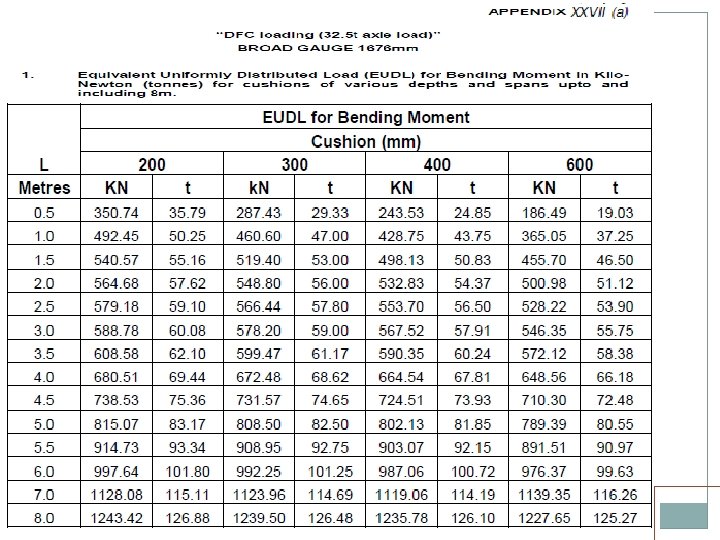
DEAD LOAD Weight of structure Permanent Load carried on it For ballasted deck bridges, 400/300 mm cushion for BG/MG. For checking old bridges 300/250 mm

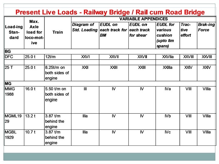
LIVE LOAD History Present Live Loads For Railway Bridges / Rail-cum-road Bridge For Foot Bridge / Footpath Live load distribution
")
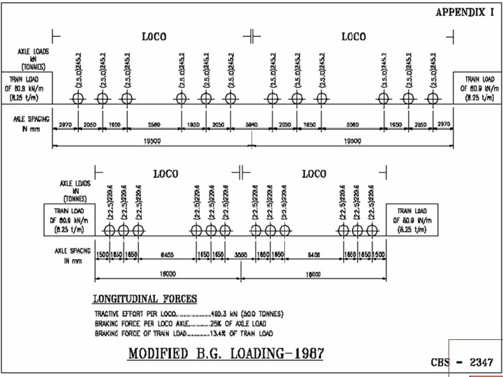
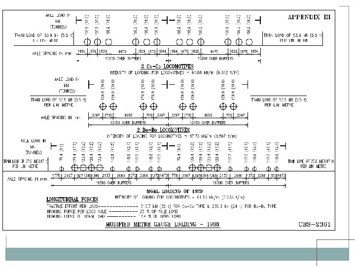
BRIDGE LOADING STANDARDS HISTORY FOR BG Loading Std. Year Max. Axle Load Engine (t) Trailing Load (t/m) Long. Force (t) Tractive Effort (t) Braking Force Std. B 1903 18. 0 1. 20 t/ft - - BGML 1926 22. 9 7. 67 47. 6 10% of T. L. RBG 1975 22. 5 7. 67 75 20% of T. L. MBG 1987 25 8. 25 100 13. 4% of T. L. + 25% of Axle Load. 25 T 2008 25 9. 33 126 -do- HM 1995 30 12. 00 135 -do- DFC 2008 25 32. 5 T/ 12. 13 t/m 126 -do-

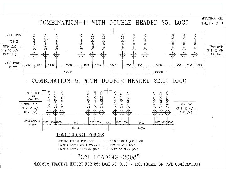
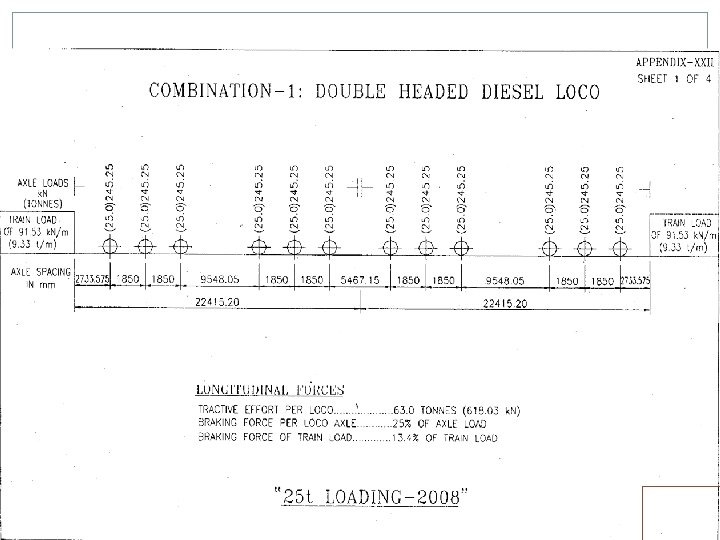
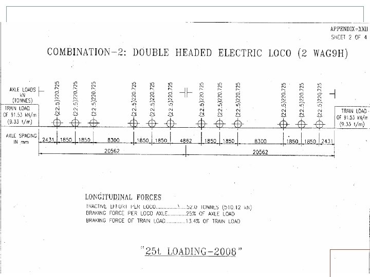
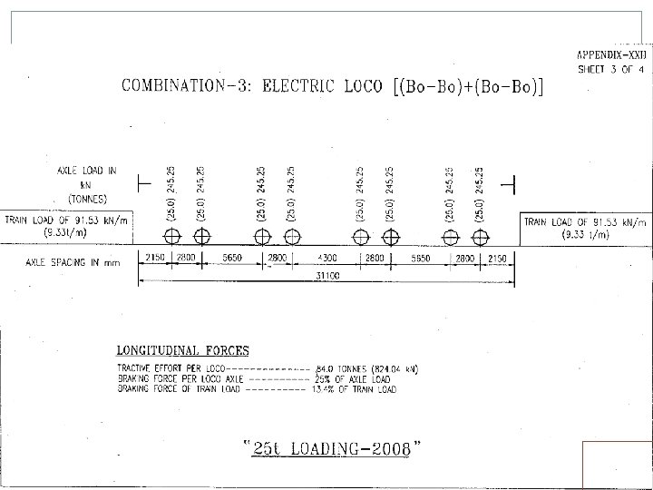
25 T LOADING Electric Locos Two WAG 9 H locos, TE of each 52 T Two 8 axle, twin BO-BO, TE of 84 T each. One in front, one in middle or back Diesel Locos Two 6000 HP locos, TE of 63 T each. Both in front Building/Rebuilding/Strengthening/Rehabilitation of Bridges for all routes except Dedicated Freight Corridor (DFC) feeder routes and DFC loading routes i. e. erstwhile HML routes. Strengthening/Rehabilitation of Bridges on Dedicated Freight Corridor (DFC) feeder routes Superstructure of Bridges being built/rebuilt on Dedicated Freight Corridor (DFC) feeder routes. In case any other loading is proposed specific approval of Railway Board reqd.
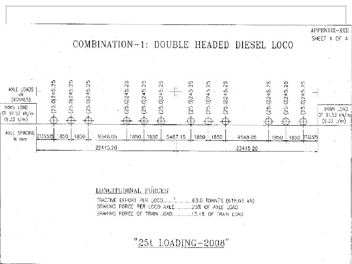
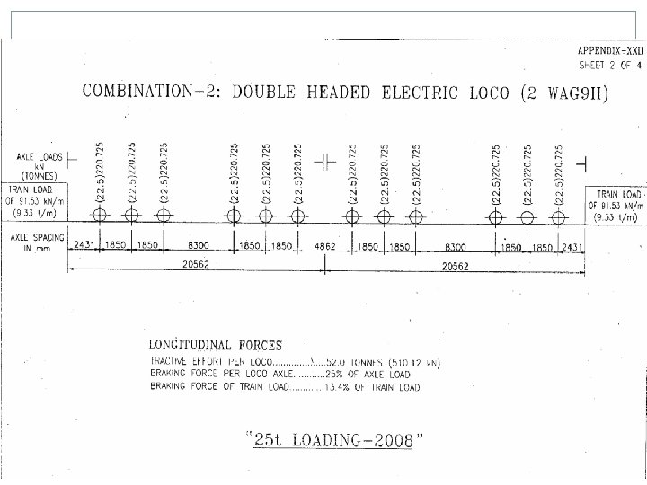
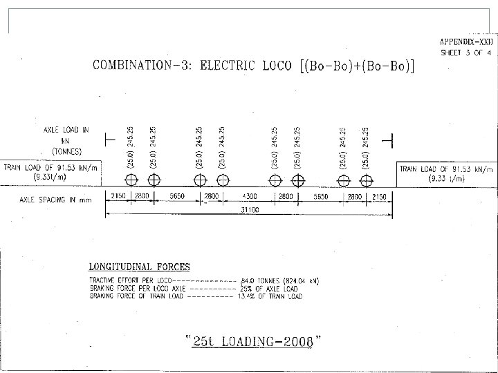

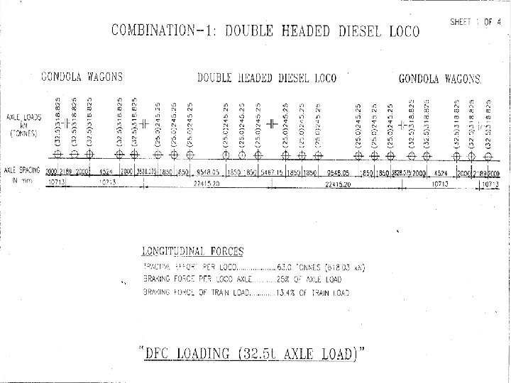
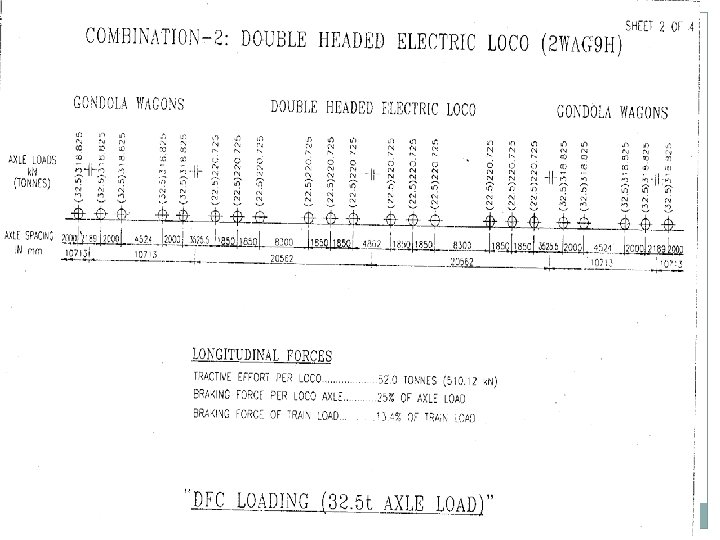
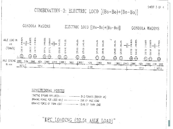
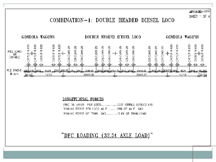
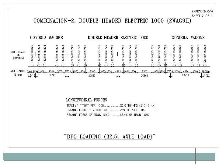
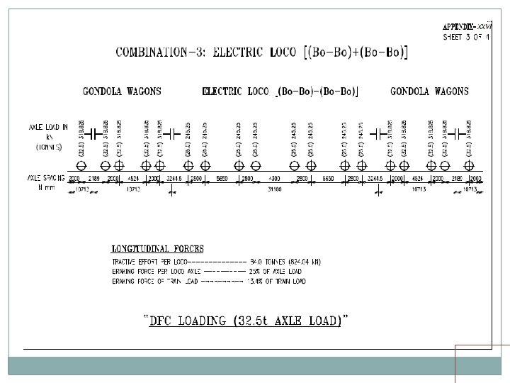
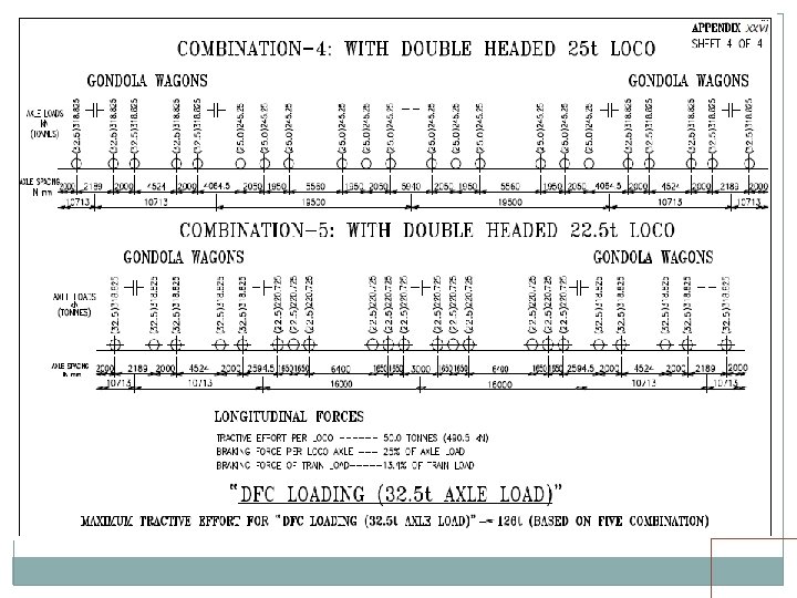
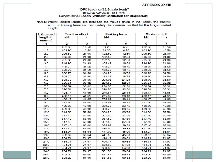
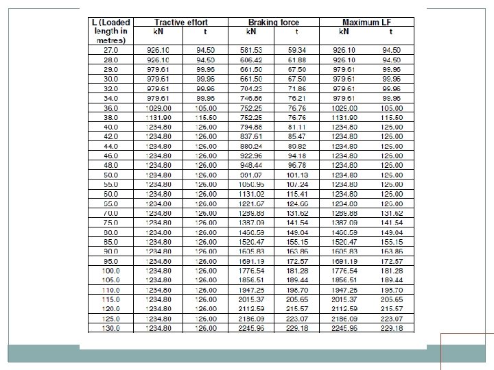
DFC LOADING Electric Locos Two pairs of WAG 9 H locos, TE of 52 T each loco. One pair in front, one pair in middle or back Two 1200 HP, 8 axle, twin BO-BO, TE of 84 T each. One in front, one in middle or back Diesel Locos Two 6000 HP locos, TE of 63 T each. Both in front The above standard should be adopted for Bridges on identified routes approved by Railway Board. Building/Rebuilding/Strengthening/Rehabilitation of Bridges on DFC loading routes i. e. erstwhile HML. Besides this, the above standard should be adopted for building/ rebuilding of substructure only on Dedicated Freight Corridor (DFC) feeder routes.


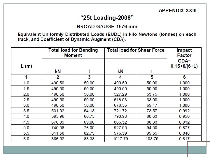
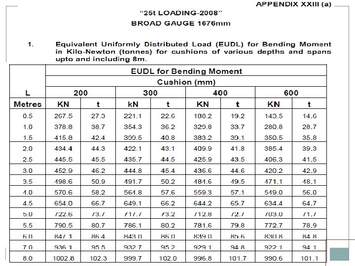
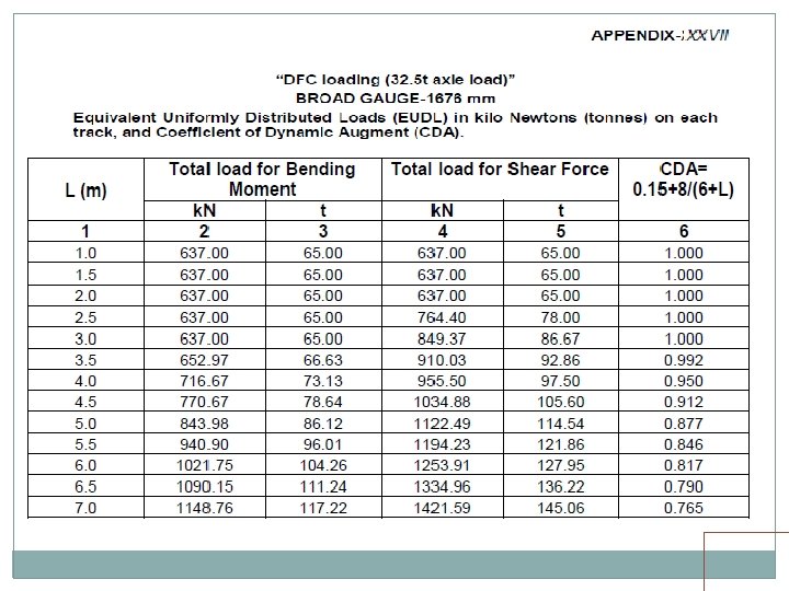
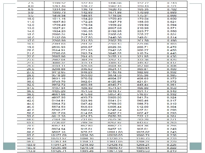
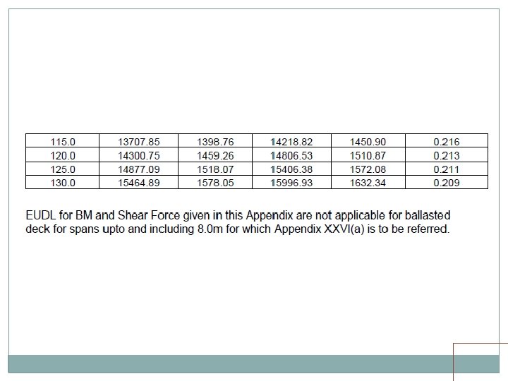
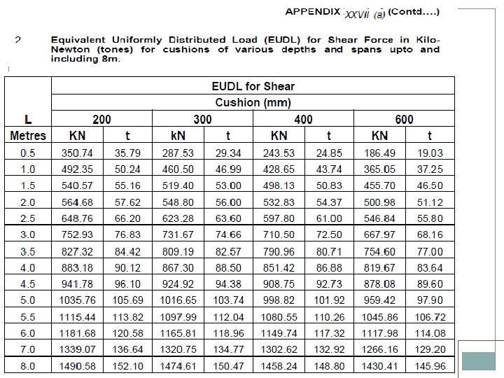
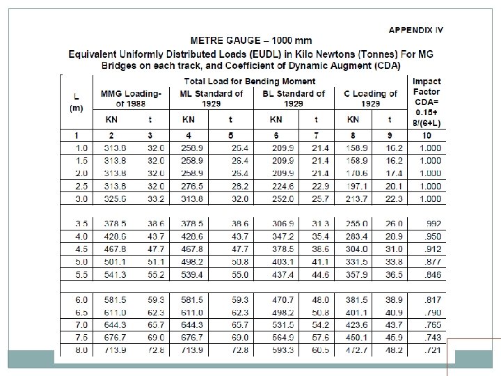
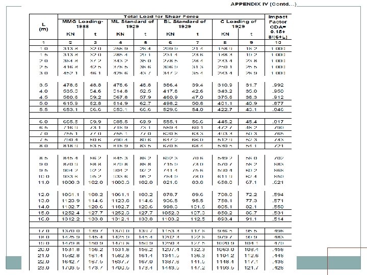
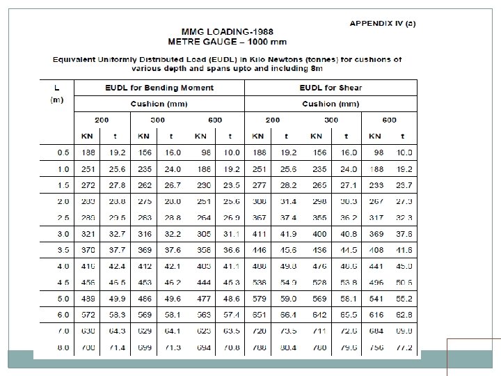
• Standard wheel/axle replaced by EUDL • EUDLs applicable to simply supported spans.

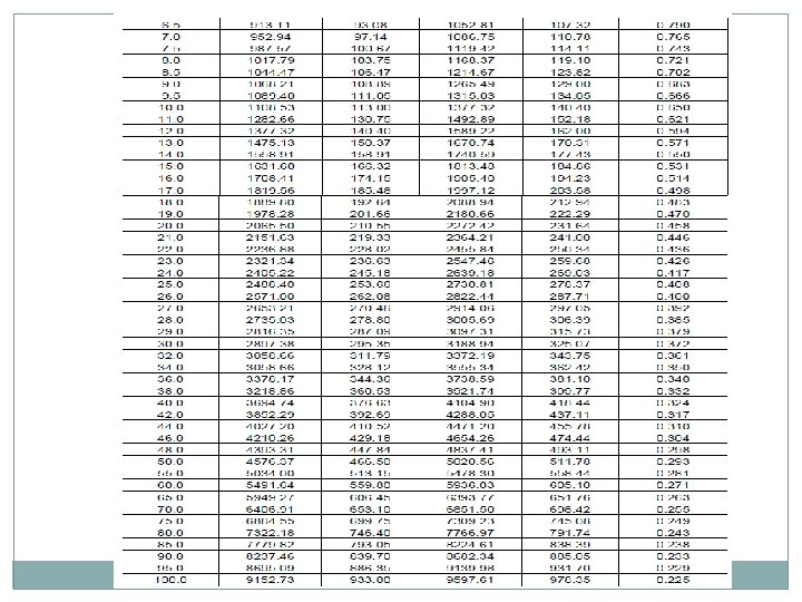
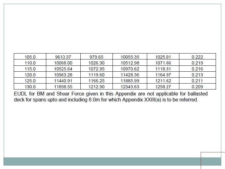
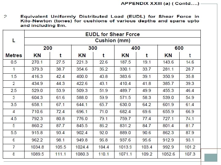
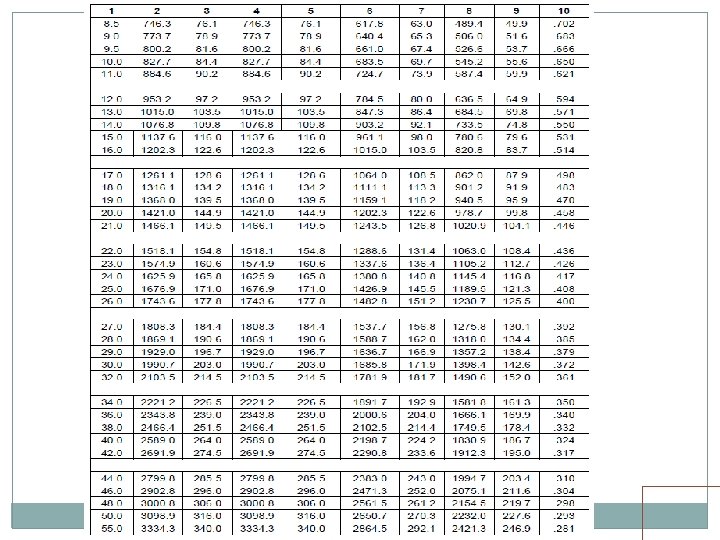
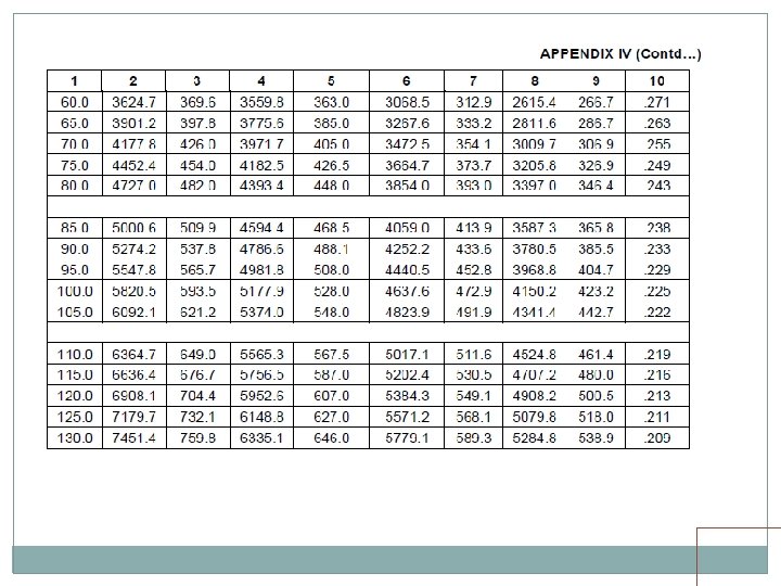
EUDL For BM For spans up to 10. 00 m >> produces BM at center = absolute BM developed by standard load For spans above 10. 00 m >> produces BM at 1/6 th span = absolute BM developed by standard load at 1/6 th of span For SF Shear force at end of span = Max. SF
 Train Loads EUDL (Span up to 10 m)")
EUDL (Span > 10 m) Train Loads EUDL (Span up to 10 m)

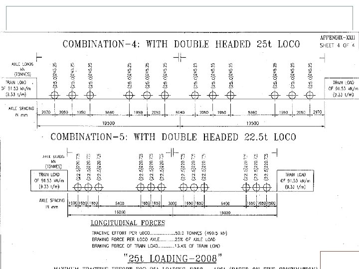
EUDL There are two load configurations for MBG loading, one 22. 5 T load and second 25. 0 T load. Note that spacing of axles is different Max. BM for spans 12 m, 15 m, 20 m, 30 m, 40 m and 50 m are caused by 22. 5 T configuration No trailing load gets loaded up to 20 m span

§ EUDL CALCULATION EXAMLE FOR 12 m SPAN The total EUDL for BM as per Bridge rules is 140. 4 T As span is greater than 10 m, BM is calculated at L/6 of span, which is 2 m in this case. The total load of 140. 4 tonnes is equal to a Uniformly distributed load(w) of 140. 4/12 = 11. 7 t/m. The Bending Moment at 1/6 of a span equal to L for a uniformly distributed load of ‘w’ t/m is equal to 5 w. L 2 /72. The BM in this case is therefore equal to 117 t-m. The configuration of MBG standard loading at which this occurs is ;
/12 = 76. 5 t RA= 6*22.")
RB= 22. 5(2+3. 65+5. 3+8. 3+9. 95+11. 6)/12 = 76. 5 t RA= 6*22. 5 -76. 5 = 58. 5 t BM at Section X = 58. 5*2 = 117 tm

LOCATIONS FOR MAX. EUDL FOR BM Span 12 m 15 m 20 m wheel 25 m 30 m wheel 40 m wheel 50 m span/6 2 m 2. 5 m 3. 33 m Wheel at span/6 Second Loco(First Bogie) Third wheel Second Loco(First Bogie) second 4. 167 m 5 m Second Loco(First Bogie) second wheel Second Loco(First Bogie) second 6. 67 m Second Loco(First Bogie) First 8. 33 m First Loco(Second Bogie) Third wheel

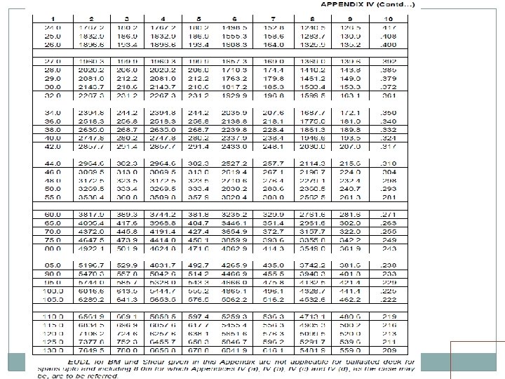
EUDL For spans up to 10 m, EUDL for BM gives same result as actual calculation For spans > 10 m to 75 m, EUDL for BM gives 2 to 8. 67 % higher result as compared to actual calculation Max. difference of 8. 67 % is for 23 m span For spans > 75 m, EUDL for BM gives same result as actual calculation

EUDL As per C. S. 37 For new bridges>> Use EUDL or actual analysis For existing bridges >> Use EUDL, in case found inadequate- use exact calculations A locomotive with axle loads heavier than standard loading or trailing load higher than specified >>> load may be considered to fall in corresponding standard loading if EUDL is less than or equal to standard loading EUDL

Foot Bridges and Foot Path For Foot bridge/Footpath on rail bridge (for design of foot path portion) 4. 8 k. Pa (490 Kg/sqm) of Footpath area Foot path on Rail cum Road or Road Bridge 4. 07 k. Pa (415 Kg/sqm) or 4. 8 k. Pa (490 Kg/sqm) where crowd loading is expected

Foot Bridge & Foot Path Cont. Loads on Footpath for designing main girder for Road or Rail bridge as per effective span < 7. 5 m 4. 07 k. Pa (415 Kg/sqm) > 7. 5 m < 30 m 4. 07 k. Pa (415 Kg/sqm) – 2. 89 k. Pa (295 Kg/sqm) Ø 30 m as per formula For Rail cum road Bridge - 1. 91 k. Pa (195 Kg/sqm)

Foot Bridge & Foot Path Cont. Loads on Kerbs 600 mm wide or more Live Load + horizontal load of 7. 35 k. N/m Less than 600 mm wide No live load only Horizontal load of 7. 35 k. N/m These loads need not be taken for design of main structure

§ LIVE LOAD DISTRIBUTION

CLAUSE 2. 3. 4. 2 Distribution through sleepers & ballast distribution area of live load on top of ballast Type II ( under each rail seat ) BG 2745 mm x 254 mm 760 mm x 330 mm MG 1830 mm x 203 mm 610 mm x 270 mm Further dispersal through fill / ballast at a slope half horizontal to one vertical. All deck slabs to be designed for both type of sleepers

Clause 2. 3. 4. 2… Cont. Distribution through R. C. Slab in right angle to slab For simply supported, fixed and continuous span 1/4 span on each side of loaded area For cantilever slabs 1/4 of loaded length on each side of loaded area. Distribution through steel troughing or beam spanning transversely As per appendix H of Steel Bridge Code

DYNAMIC EFFECT Accounted for by a static load equivalent to CDA multiply by LL. For Railway Bridges (Steel) CDA for BG /MG Single Track (speed 160/100) CDA = 0. 15 + 8 / (6+L), Max. Value-1. 0 where L is i) Loaded length giving maximum stress ii) 1. 5* Spacing of cross girder ( For Stingers) iii) 2. 5* Spacing of cross girder (For Cross girder)
 / Cross")
DYNAMIC EFFECT CONT. For Multiple Track further multiply by Main girders (outer) / Cross girders - 0. 72 Main girders (Intermediate) - 0. 6 Fish plated Track on steel troughing / steel sleeper CDA = 7. 32 / (B + 5. 49) For BG CDA = 5. 49 / (B + 4. 27) For MG where B is spacing between main girder CDA for narrow gauge (762 mm or 610 mm) CDA = 91. 5 / (91. 5 + L)

DYNAMIC EFFECT CONT. CDA for Foot Bridge No allowance CDA for combined Rail - Road Bridge As per Rail Bridge Turn table girders Designed for CDA of 10% of LL Additional allowance of 100% in all on an axle which is placed at one end of turn table.

DYNAMIC EFFECT CONT. CDA on pipe culvert, Arch Bridge, Concrete slab / conc. girder (span < 25 m) At zero fill -- Same as steel girder At fill < 900 mm -- Gradually reduced to 1/2 At fill > 900 mm -- reduced to zero in next 3 m. Applicable to multiple tracks also- except Arch Bridge span > 15 m, where CDA reduce to 2/3 rd

FORCES DUE TO CURVETURE AND ECCENTRICITY OF TRACK On ballasted deck, even on straight line Designed for 100 mm eccentricity On a curved Bridge Designed for centrifugal action of moving load taking all tracks occupied Horizontal load due to centrifugal force is C = WV 2 / 12. 95 R k. N/m run Where W= Equivalent distributed live load in k. N/m V= Maximum speed in Kmph R= Radius of curve in m It assumed to act at 1830/1450 mm for BG/MG above rail level

TEMPRATURE EFFECT Applicable for Portion of Bridge not free to expand / contract Temperature limits be specified by Engineer. Coefficient of expansion For steel & RCC -- 11. 7*10 -6 per degree C For plain concrete -- 10. 8*10 -6 per degree C

FRICTIONAL RESTISTANCE OF EXPANSION BEARING Coefficient of frictional resistance of expansion bearings are Roller bearing Sliding bearings of steel on 0. 03 Cast Iron or Steel 0. 25 Ferrobestas 0. 20 Hard copper alloy 0. 15 Sliding bearing of PTFE / Elastomeric 0. 10 Conc. Over conc. with bitumen layer 0. 50 Conc. Over conc. Not intentionally roughened 0. 60

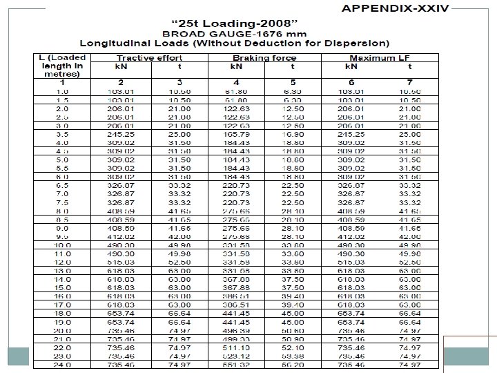
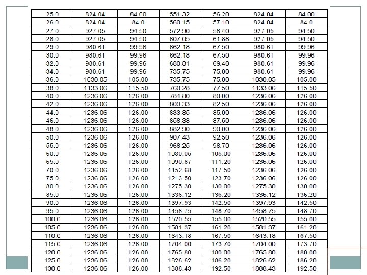
LONGITUDINAL FORCES One or more of following be considered Tractive Efforts Braking Force Resistance to movement of bearing due to change of temperature and deformation of girder should not be more than the limiting resistance at the bearing. Forces due to continuation of LWR/CWR on Bridges

Long. Forces Cont Loaded Length for simple supported span One span for Girders stability of abutments stability of pier carrying one fixed/ one free bearing One span / two span Stability of pier carrying fixed / sliding or elastomeric bearings Longitudinal force shall be divided proportional to their length for two span loading condition. Loaded Length for continuous span Appropriate loaded length giving worst effect

Long. Forces …Cont No increase for dynamic effects Transferred horizontally through Knuckle pin for bearing having rocking arrangements. Girder seats for sliding, elastomeric or PTFE bearings

Long. Forces Continuation Of LWR/CWR

Long. Forces. . Cont Distribution of Longitudinal Forces Substructure with sliding / elastomeric bearings Abutment 50% Pier 40% Multi-span Bridge Also check for 20% net longitudinal force from adjoining span with directly supported span as unloaded. Spans with roller / PTFE bearings at one end 100% at fixed end

Long. Forces. . Cont. Dispersion of longitudinal forces 25% of longitudinal force subject to minimum of 16 t for BG, 12 t for MMG or MGML and 10 t for MGBL This applies to • open deck bridges having through welded rails, rail-free fastening and adequate anchorage of welded rails on approaches(minimum 30 m). • open deck having jointed track with rail free fastening or ballasted deck, however without any SEJ or mittred joints in either case. Can increased to 35% in case suitably designed elastomeric bearings provided

Long. Forces Cont. Dispersion shall not exceed the capacity of track for dispersing the longitudinal force nor shall exceed the capacity of anchored length of track on approaches to resist dispersed longitudinal force. In case multi-span bridges having continuous spans, or flexible supports, or flexible bearings on all supports, or any other special features which are likely to affect distribution/dispersion of longitudinal forces significantly, the dispersion/distribution of longitudinal forces shall be determined by suitable analysis. For design of new bridges or rebuilding of existing bridges, dispersion of longitudinal forces shall not be allowed (CS no 36)

Long. Forces Cont. Where bridge carries more than one track Shall be considered to act simultaneously on all track Maximum effect on any girder with two tracks be allowed for, but With more than two tracks, a suitable reduction be made for additional tracks. 90% for 3 Tracks and 75% for 4 or more Tracks With Seismic forces Only 50% T. E. /B. F. after distribution/dispersal

RACKING FORCES Not accounted for calculating stresses in main girder For design of lateral bracing Span > 20 m additional lateral force of 5. 88 k. N/m (For DFC 13. 72 k. N/m) as moving load in addition to wind and centrifugal force Span upto 20 m For spans less than 20 m, wind stresses are not calculated. For designing lateral bracing, 8. 82 k. N/m (DFC 16. 66 k. N/m) due to wind & racking forces in addition to centrifugal forces

FORCES ON PARAPETS Minimum height one meter above adjacent roadway/foot way surface Designed for a lateral horizontal and a vertical force of 1. 47 k. N/m applied simultaneous at top of the railing/parapet

WIND PRESSURE EFFECT Basic Wind pressure Equivalent static pressure in the wind ward direction Depends on appropriate wind velocity choosen as per local meteorological records & degree of exposure map given in IS 875 -Part 3 be used in absence of meteorological records

Wind Pressure Effect Cont. Wind Pressure for railway / foot bridges Wind pressure specified shall apply to all loaded / unloaded bridges except Bridges does not carry live loads when wind pressure at deck level exceeds. For BG 1. 47 k. N/sqm (0. 98 k. N/sqm for checking old bridges) For MG & NG 0. 98 k. N/sqm For Foot Bridge 0. 74 k. N/sqm

Wind Pressure Effect Cont. exposed area for Unloaded span & trestles except plate girders 11/2 time of horizontal projected area Plate girders Area of windward girder + Area of leeward girder x a factor (depending on spacing v/s depth of girder) clause 2. 11. 3. 1 loaded span Horizontal projected area of moving load from 600 mm above R. L. to top of highest stock + exposed area of balance portion as unloaded span

Wind Pressure Effect Cont. Effect of wind pressure be considered as Lateral effect on the top chords and wind bracing considered as a horizontal girder Same effect on lower chords Vertical loads on the main girders due to overturning effect of wind pressure Bending & direct stresses in members transmitting the wind load from top to the bottom chords or vice-versa

Wind Pressure Effect Cont. Clause 3. 11. 1

Forces and Effect due to Earthquake Seismic Force Acts in three mutually perpendicular directions Horizontal (Two Directions) Vertical For determining seismic forces country is divided in 4 zones Basic horizontal Seismic Coefficient defined for each zones Coefficient be gradually reduced to 50% from ground level to 30 m below. (GL is scoured bed level corresponding to mean flood)

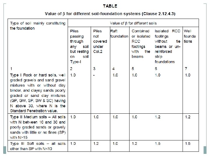
Seismic Force Cont. Design of Bridges for Seismic Force Design Seismic force is computed taking into consideration of Importance of the structure ( Imp Br 1. 5, Other Br 1. 0) Soil foundation system Acts at center of mass of elements into which bridge is conveniently divided. Bridge as a whole and every part of it be designed and constructed to resist stresses

Seismic Force Cont. Soil foundation system

Seismic Force Cont. Slab, box and pipe culvert >> no seismic forces Seismic forces for design of bridge in different zone Zone II to III -for bridges of length >60 m & span >15 m Zone IV &V -all bridges Masonry & Plain concrete Arch Bridges more than 12 m span shall not be built in Zone IV & V Horizontal seismic force due to live load on bridges be ignored when acting in the direction of traffic. Horizontal seismic force due to live load on bridges be considered 50% of design live load when acting perpendicular the direction of traffic.

Seismic Force Cont. Modal analysis is necessary in Zone IV & V for Design of cable stayed, horizontal curved girder, RCC arch and steel arch bridge. Height of sub structure is more than 30 m or span is more than 120 m In case of possibility of amplification of vertical seismic coefficient for Important Bridges.

Seismic Force Cont.

Seismic Force Cont.

Seismic Force Cont.

Seismic Force Cont.

Seismic Force Cont.

ERECTION FORCES AND EFFECTS Erection Forces to be considered Weight of all permanent and temporary material All other forces and effects which can operate on any part during erection Allowance be made in design for stresses set up in any member during erection.

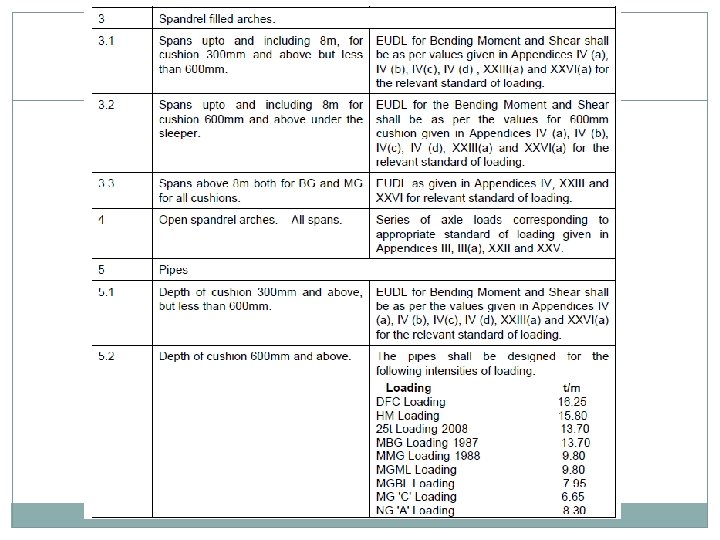
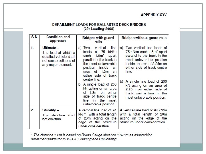
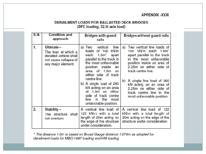
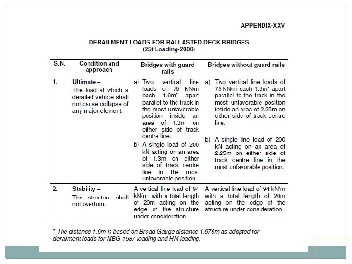
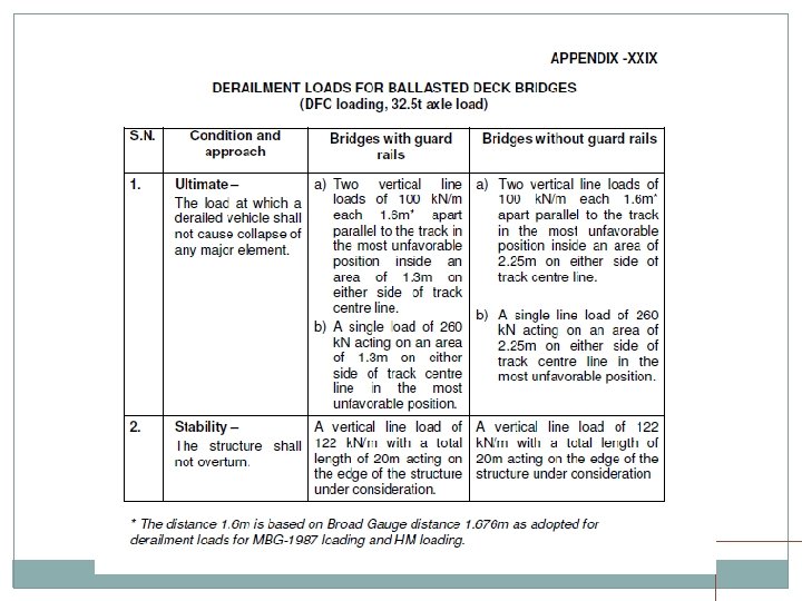
DERAIRELMENT LOADS Derailment loads for BG for ballasted deck bridges as per appendix XXV / XXIX for 25 t / DFC loading. Load specified shall be applied at top of ballast Load assumed to disperse at a slope of half horizontal to one vertical.

PQRS LOAD Should be considered for reduced coefficient of dynamic augment for 20 KMPH as per appendix X for most unfavorable position. The load due to auxiliary track shall be considered separately. The dispersion of load shall be as per clause 2. 3. 4. 2

PQRS LOAD

ASSESSING STRENGTH OF EXISTING BRIDGES As per existing Bridge Rules except Modification in CDA Modification in Longitudinal Forces Modification in Wind force Modification in Method for checking for Live Load

EXISTING BRIDGES CONT. Modification in CDA If no Rail joint on span or within 10 m CDA can be reduced by 0. 75/ span in m. Max. reduction 20% up to span 7. 5 m If maximum speed is not increased CDA can be multiply by Vr/V, where Vr is permissible speed and V is 125/80 kmph ( Electric/steam)for BG & 100/60 kmph for MG Bridges found fit for 125 kmph can be cleared for 160 kmph. CDA in no case be less than 0. 1

EXISTING BRIDGES CONT. Modification in Longitudinal Forces Generally clause 2. 8 shall apply. For trains hauled by steam Locos Max. TF 25% of axle load of coupled wheels on actual engines under consideration. Max. BF 20% of actual braked engine axle loads + 10% of other braked axle loads.

EXISTING BRIDGES CONT. For trains hauled by diesel or AC or DC Locos Max. TF As specified equally distributed amongst driving axles. Max. BF As specified for Locos equally distributed amongst braked axles + 10% of weight of braked trailing axles covering loaded length (for vacuum brakes) OR As specified for air brakes subject to max. of 13. 4% of weight of braked axles.

EXISTING BRIDGES CONT. Modification in Wind force For checking for Rolling Stocks involving higher loads Bridge shall not be considered carrying any Live Load when wind pressure at deck level exceed 0. 98 k. N/sqm Modification in Method for checking for Live Load for checking Bridges for higher loading BM & SF shall be calculated as per EUDL given for different loading In case found inadequate check for actual axle load using RDSO software “Moving Loads”

CRITICAL SPEED Critical speed is defined as the speed at which the external forcing frequency will be equal to one of the natural frequencies of the track-bridge-vehicle system, contributing to vertical response of the bridge Critical speed in the case of steam locomotives and for open web girders only may be calculated by any of the following methods by running trains at varying speeds across the bridge and determining the speed giving the maximum deflection

CRITICAL SPEED by ascertaining the maximum static deflection under live load and applying the following formula

CRITICAL SPEED By following Approximate formula Speed restriction on open web girders for steam traction in the rang of Critical Speed ± 10 Kmph should be avoided.

- Slides: 120