Bridge Inspection Robot Proposal Presentation Sean Csukas Kristen

Bridge Inspection Robot Proposal Presentation Sean Csukas Kristen Fernandez Erikzzon Latoja Justin Tamayo Sanmeshkumar Udhayakumar Advisor: Dr. Patricio Vela

Previous Design by Dr. Wang’s Team Introduction • The team designed a wireless sensing robot for structural health monitoring of steel structures • Replaced the old flexure-based, fourwheeled robot with a design that features upgraded electrical and mechanical components along with increased mobility Current Design

Problem Background • The repair and maintenance of civil infrastructure systems is a constant challenge • • 50+% of U. S. bridges built before 1940’s 1 in 9 structurally deficient Maintenance costs ~$20. 5 billion annually; only $12. 8 billion available American Society of Civil Engineers (ASCE) gave C+ grade for bridge infrastructure in 2017 Report Card on America’s Infrastructure • Visual inspection subjective and leaves damage below surface undetectable
 System • Utilizes accelerometer and other sensor data •")
Solution: Structural Health Monitoring (SHM) System • Utilizes accelerometer and other sensor data • Current Solutions - Stationary sensors • Cons • Cable installation between sensors is high cost • Hard and time consuming to place and maintain • A lot of sensors needed • Resensys Senspot Sensors • For average-sized highway bridge, would need ~500 sensors * $20 = $10, 000, not including installation costs • Human installation required roughly every 20 years

New Solution: Network of Wireless, Sensing Robots • Network of robots capable of synchronized, autonomous traversal and structural health measurement • Benefits • Only small number of robots needed to cover whole bridge • Low-cost and no installation • Challenges • No similar existing solution • Drastically more complex

Goals • Design and build one robot to compose the new network • The robot must be able to do the following: • Horizontally and vertically traverse steel bridges • Measure bridge vibrations at low frequencies • Wirelessly transmit vibration data to a PC • Lightweight for deployment and retrieval by drone

Outline • Microcontroller • Wireless Data Transmission • Motor Choice and Implementation • Power • Magnets • Robot Structure • Accelerometer Measurements • Verification • Accelerometer Choice • Final Demonstration Results • Data Filtering • Robot Overview • Mobility Design • Accelerometer Deployment • Motion Tracking

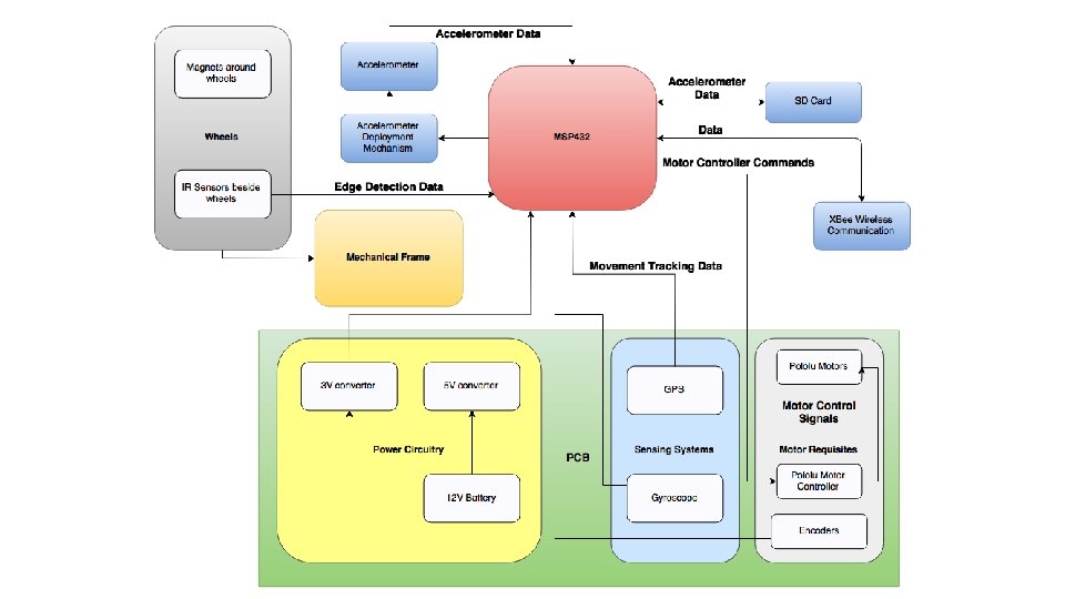
Robot Overview

Robot Mobility

Three-Wheeled Design • Two motorized wheels in the front and passive omni-wheel at the back • Permanent magnets • Surround motorized wheels • Adjacent rear omni-wheel

Mobility Choice: Three-Wheeled Design • Pros • Retains capabilities of old flexure-based design • Turn in place capability • Less weight and power consumption compared to original design • Cons • Omni-wheel provides less stability • Currently lacks ability to traverse 90° angle • Potential Solution: • Leverage Arm • Motorize back wheel

Motors - Pololu 25 D Metal Gearmotor • Motor includes encoder with 1200 counts per revolution • Includes low power option at 12 V • Free-Run Speed: 55 rpm • Free-Run Current: 100 m. A • Provides high torque needed for vertical traversal • Stall Torque: 115 oz∙in • Stall Current: 1110 m. A

Motors - Implementation • Motors placed in line with length of robot in order to minimize width • Two beveled gears used to transfer motion 90° to wheels • Encoders provide 1, 200 counts per rotation of the wheel • Travelling one meter returns 4000 counts per wheel • Magnets are placed along the surface of the wheel • Keeps robot attached to bridge on any surface

Magnets - B 621 Grade N 42 Neodymium Magnet • Material: Nd. Fe. B, Grade N 42 • Weight: 0. 36 g/magnet • Dimensions: 3/8” x 1/16” thick • Holding Force: 1. 15 lbs. • Initial magnet choice was too large and too strong • Motors had trouble producing enough torque to overcome holding force • Due to size, initial magnets surrounding the wheel circumference turned the wheel into a polygon • Chosen magnet was half the width to form a more uniform circle

Accelerometer

Accelerometer Design Choices Parameters Initial Accelerometer: Silicon Designs 2460 -002 Final Accelerometer: Analog Devices ADXL 355 Acceleration range ± 2 g ± 2. 048 g Frequency Range 0 -300 Hz 0 -10, 000 Hz Resolution: 38 ng/bit (with 2000 x gain) 3. 8 ug/bit Noise Specification: 10 μg/√Hz (before signal conditioning and A/D) 25 μg/√Hz Operating Power: 276 m. W (without A/D) 495 μW Mass 21 g (without cabling and A/D) ~5 g

Reason for Accelerometer Change • Noise Floor Requirements relaxed upon further conversations • MRDC Bridge very small in comparison to other bridges • Higher sensitivity needed for small structures • Digital over Analog • Initial trepidation due to unfamiliarity • Much less noise than analog • Controlled environment within one module • I 2 C bus hard to create noise in • Can easily change digital filter parameters • No PCB for signal conditioning module needed • Faster prototyping

Accelerometer Deployment Method • Requirements • Accelerometer shall mount directly onto bridge • Accelerometer shall be flush with bridge to ensure accuracy of measurements • Design incorporated vertical motion w. r. t. the Bridge Inspection Robot frame

Linear Actuator - Actuonix L 12 30 mm Linear Actuator • Prepackaged solution • Very low mass • Potentiometer already available for control • Gear Ratio: 210: 1 • Max Force: 80 N • Stall Current @ 12 V: 180 m. A • Control: RC

Deployment • Feedback not useful for control • 210: 1 Gear Ratio made Linear Actuator was able to lift robot up off of magnetized surface • Solution was to set input value to match the accelerometer position to exactly level with the contact surface of the wheels. • Accelerometer deployed inverted along the z-axis • Allowed for accelerometer on board to be directly in contact with measurement surface • Z-Axis Data only needed to be multiplied by -1 in post-processing to resolve
 or firgr() •")
Digital Filter Parameters Option • Digital Filtering through Matlab • firceqrip() or firgr() • FIR Filter • Linear phase delay

Motion Tracking

Motion Tracking Requirements • Assumptions • Initial orientation is known • Only straight path traversal is required for the most part, with turning used for path corrections • Requirements • Need to go in a roughly straight path so robot won’t need to continuously correct path • Need to be able to detect edges so robot won’t fall off • Need to be able to identify locations of structural health measurements to around about 2 m resolution fairly accurately as in experiment in thesis paper

Straight Path Traversal • Encoders alongside proportional control used to maintain straight path • Drift likely minimized due to permanent magnets holding wheels and robot body to metal surface • Potential drift still a concern • No permanent reference point • Plans to implement gyroscope in design for future use

Edge Detection • IR Sensors • Four IR sensors mounted close to wheels and near edge • Verified that wheels will hit inclines such that sensors will not scrape against surfaces IR

IR Sensor Implementation

Motion Tracking • Used encoder movement, combined with GPS for absolute position recalibration every 50 m • Further minimizes effect of encoder drift • Not useful if on underside of bridge without clear line-of-sight of the sky • Incorporate gyroscope in a future robot iteration

GPS - Adafruit Ultimate GPS Breakout - 66 Channel MTK 3339 • Accuracy: 3 m radius • Update Frequency: 10 Hz • Sensitivity: 165 d. Bm • Power: 100 m. W • Interface: UART • Other • Ships with breakout board • Built-in data-logging • SMA connector to connect external antenna

Gyroscope – ST L 3 GD 20 H • X-, Y-, Z-axis data • Resolution: ± 245/± 500/± 2000°/s with 16 bits • Accuracy: Zero Bias: ± 25°/s • Power: 15 m. W • Interface: SPI/I 2 C • Other: User-enabled integrated low-pass and high-pass filters; Temp sensor.

Data Storage

SD Card – Sparkfun micro. SD Breakout • Connects San. Disk Class 4 16 GB micro. SD card to MSP 432 • Capable of storing over 370 hours of accelerometer data at a sample rate of 1000 Hz • Interfaced via SPI • R/W Speed: 1 MHz

Wireless Communication

Wireless Module - XBee S 2 C 802. 15. 4 • Specifications • • • Max outdoor range: 1200 m Throughput: up to 250 Kbps Interface: UART Current draw (typical): 28 -33 m. A Wireless Protocol: IEEE 802. 15. 4 • Switched from Digimesh • Communicates with PC through a Sparkfun XBee Explorer USB

Power

Power Requirements • Power requirements were mainly dependent on the following: • • Motors Wireless Communication Accelerometer Deployment • The robot was expected to run actively for at least one hour and one additional hour while stationary • The robot required a maximum voltage of 12 V to accommodate the accelerometer and motors. Power conversion circuitry used to create lower voltages for other components
 • Configuration:")
Turnigy Lipo Pack • Minimum Capacity: 2200 m. Ah (True 100% Capacity) • Configuration: 3 S 1 P / 11. 1 v / 3 Cell • Weight: 188 g • Provides a high continuous current and long lifetime

Robot Structure

Structure • A holding structure is needed for battery and circuitry • Structure was rapidly prototyped using Inventor 2017 and 3 D printing with the Senior Design Lab • Alternate Consideration • Aluminum or acrylic sheets are used for a high strength support, designed in Inventor 2017 and machined at the invention studio.
 • Designed using the educational license of Autodesk Eagle. CAD")
Printed Circuit Board (PCB) • Designed using the educational license of Autodesk Eagle. CAD • Single circuit board for power, data transmission, and motor control • Used for routing signals between subsystems • Implements modular design to allow detachment or replacement of major components

Microcontroller

Microcontroller – TI MSP 432 P 401 R • Specifications • • • 48 MHz ARM 32 -bit CPU 256 k. B of flash memory 64 k. B SRAM 14 -bit ADC 4 UART channels and 4 SPI channels Current draw (active mode, typical): 7. 8 m. A • Programmed via Code Composer Studio IDE • MSP 432 Launchpad used for rapid prototyping

Software • Written in C • TI-RTOS: a proprietary RTOS for TI MCUs • Libraries for GPIO, ADC, UART, SPI, Timers, etc. • Separate threads for different components • Mutexes, semaphores, and barriers sync and coordinate actions • External libraries for motors and GPS ported from Arduino to MSP 432

Datalogging Program • A "sample" consists of an Xvalue, Y-value, and Z-value • Accelerometer provides sequential data in sets of 8 samples • Double buffer system on MSP 432, each holding 1536 samples • Accelerometer fills one buffer with data while SD card is filled with the other buffer's data

Movement Program • While motors are running. . . • Encoder counts are incremented/decremented via interrupts • Running timer regulates proportional control on the motors • IR sensors halt forward progress if edge detected • Motors stop when the desired encoder count (distance) is reached
 • Accelerometer")
User Interface Program • Commands are sent through a serial port (XBee) • Accelerometer data is streamed back at 115200 baud • Data can be piped to a MATLAB program for automatic plotting

Design Verification Characteristic Magnet Holding Force Operational Lifetime Specification Holds robot static indefinitely Movement Operation Time ≥ 1 hour; Recording Operation ≥ 1 hour Accelerometer Range and Accuracy 0 – 50 Hz ± 0. 5 Hz 50 Hz +/- 0. 5 Hz Robot Size Greatest side length ≤ 0. 25 m Weight Wireless Communication Distance Total mass ≤ 1 kg Able to send/receive data ≥ 800 m Path Following Shall not fall off edge in “sunny day” conditions

Dimension and Mass Properties Dimensions Weights Required Specification <= 25 cm by 25 cm Actual Requirement Specification Met? 24 cm by 14 cm YES by 20 cm 1 kg 1. 084 kg (5 -7% No overshoot on scale)

Test Event: Holding Force • Initially proposed test was to check if an individual magnet could maintain its position with mass attached to it for at least 2 minutes • On further discussion, a more representative test would be testing the fully built robot with some mass attached to it in multiple configurations • Requirement is verified if robot can maintain its own mass and position in varying positions • Stretch goal is the robot being able to maintain its position with extra mass attached

Holding Force Results • Robot upside down: Maintained position for at least 2 minutes • Robot on vertical surface: Maintained position for at least 2 minutes • Robot is more secure if front wheels are on top • If back wheel is on top, increased likelihood of the robot will flip over • If robot is sideways, increased likelihood of back wheel slipping

Test Event: Accelerometer Data Accuracy • Verification of the accelerometer data accuracy required usage of a shaker table • A vibration profile will be measured by mounting both a statically mounted accelerometer and the robot with its installed accelerometer on to the table

Accelerometer Data Accuracy Results • No official testing event has occurred yet • Based on examination of data while integrating accelerometer into robot design, confident in accelerometer functionality • Data produced is along the appropriate axes • Small perturbations distinct

Test Event: Battery Life • Battery life analysis will be divided into movement operation time and measurement operation time • Movement operation time will be measured by having the motors drive continuously on metal surface as if it were traversing a bridge • Measurement operation time will be measured by having the robot collect ambient vibration data • Requirements will be met if each lifetime surpasses one hour

Battery Life Results • Upon further discussion, the highest current draw would be during the robot movement as the motors are driven • By verifying the movement battery life requirement, the measurement battery life requirement is also verified • The robot was set to spin wheels freely while attached to a multimeter • 0. 25 V for 1 hr • Not completely representative as there is higher current draw when wheels are under load and magnetized to metal surfaces

Test Event: Wireless Communication Distance • The robot shall send data at distances varying linearly from 500 m to 1000 m to a base computer • Communication distance is verified if it can accurately send data at least 800 m away from the computer

Wireless Communication Distance Results • Initial test sent GPS data back to base computer along 10 th Street to the north of Georgia Tech’s main campus • GPS data gave out at approximately 500 m • Concerns regarding the foliage and passing cars obfuscating the signal • Retest to take place at Piedmont Park • More open space and clearer line-of-sight between robot and PC

Test Event: Final Demonstration • The robot will be placed on the MRDC bridge and be expected to traverse to one of the measurement locations in each configuration • At each configuration, the robot will take measurements at one location simultaneously with stationary sensors at the remaining locations and send the data to the base computer • Measurement accuracy will be further confirmed by striking the bridge with a hammer during measurements

Final Demonstration • The “bridge” has been brought to the presentation • The robot shall: • Move along the “bridge” • Stop after moving for four seconds • Robot should not fall off • Deploy the accelerometer • Measure data • Transmit data wirelessly to PC • Data shall be plotted in MATLAB • Repeat the above procedure in triplicate

Future Steps • Integrate gyroscope for complex path following • Create network of robots for full mobile sensing network • Modify robot for drone deployment and retrieval • Incorporate localization

Cost Analysis

Questions?

Before Low pass with 0. 5 attenuation After Low pass with 0. 5 attenuation
- Slides: 64