
BRIDGE DESIGN Chapter 3 ANALYTICAL PROCEDURE Dr Shahiron

BRIDGE DESIGN Chapter 3: ANALYTICAL PROCEDURE Dr Shahiron Shahidan shahiron@uthm. edu. my drshahironshahidan. weebly. com

Outline • • Fundamental Concepts Influence line Analysis Collapse Analysis Grillage Analysis

3. 1 Fundamental Concepts • Structural analysis is essential in bridge analysis. It is part of simplified mathematical modelling of the response of a structure to the applied loading. • Model are based on the idealizations of the structural behaviour of the material, depending upon the simplifying assumption in modelling.
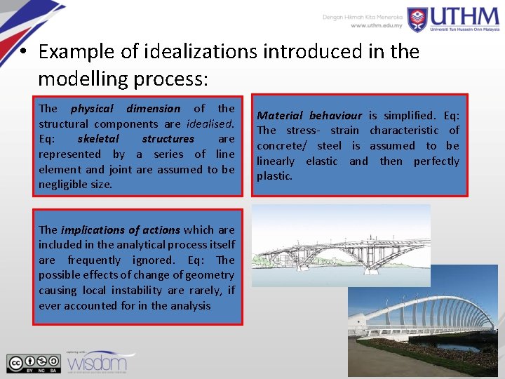
• Example of idealizations introduced in the modelling process: The physical dimension of the structural components are idealised. Eq: skeletal structures are represented by a series of line element and joint are assumed to be negligible size. The implications of actions which are included in the analytical process itself are frequently ignored. Eq: The possible effects of change of geometry causing local instability are rarely, if ever accounted for in the analysis Material behaviour is simplified. Eq: The stress- strain characteristic of concrete/ steel is assumed to be linearly elastic and then perfectly plastic.

Stress distribution on the bridges

Bridges Failure The entire span of the Interstate 35 W bridge collapsed in Minneapolis, 2007 Putrajaya, Malaysia, 2013 Mianus Bridge, Greenwich, June 28, 1983

3. 2 INFLUENCE LINES
3. 2. 1 Introduction • In this chapter will be discussed: – the moving load from one point to another point such as the live loads for bridge – because of the moving vehicles – represents the variation of the reaction, shear, moment or deflection at a specific point in a member as a concentrated force moves over the member.
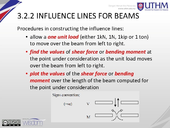
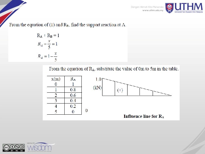
3. 2. 2 INFLUENCE LINES FOR BEAMS Procedures in constructing the influence lines: • allow a one unit load (either 1 k. N, 1 kip or 1 ton) to move over the beam from left to right. • find the values of shear force or bending moment at the point under consideration as the unit load moves over the beam from left to right. • plot the values of the shear force or bending moment over the length of the beam computed for the point under consideration
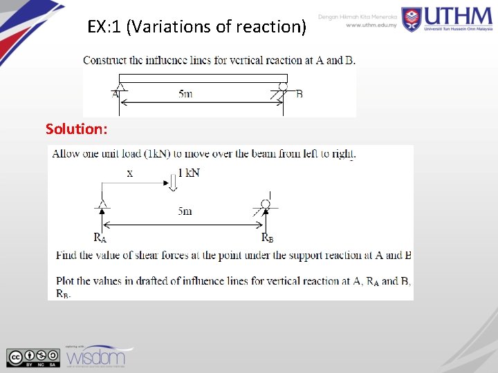
EX: 1 (Variations of reaction) Solution:

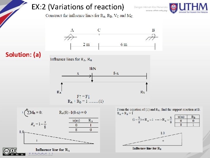
EX: 2 (Variations of reaction) Solution: (a)
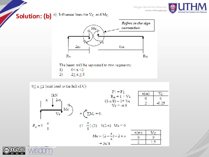
Solution: (b)
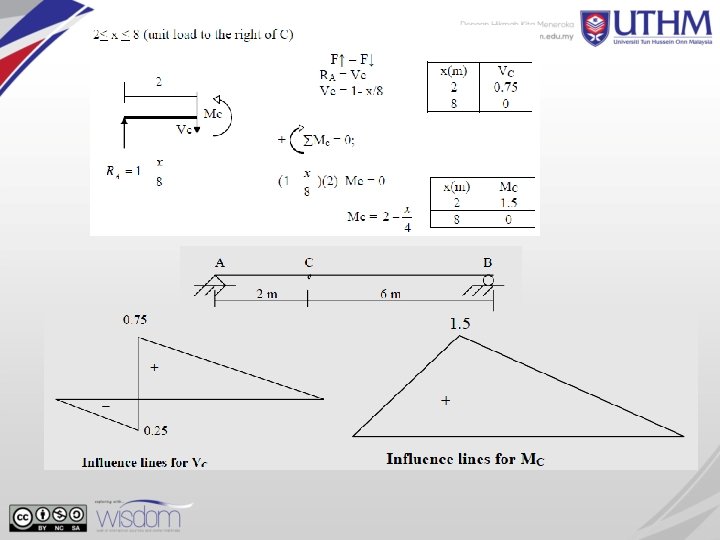
3. 2. 3 -QUALITATIVE INFLUENCED LINES – -MULLER-BRESLAU’S PRINCIPLE • The principle gives only a procedure to determine of the influence line of a parameter for a determinate /indeterminate structure • But using the basic understanding of the influence lines, the magnitudes of the influence lines also can be computed • In order to draw the shape of the influence lines properly, the capacity of the beam to resist the parameter investigated (reaction, bending moment, shear force, etc. ), at that point, must be removed • The principle states : The influence line for a function (e. g. reaction, shear, moment) at a point, is to the same scale as the deflected shape of the beam when the beam is acted upon by that function. – The capacity of the beam to resist that parameter, at that point, must be removed. – Then allow the beam to deflect under that parameter – Positive directions of the forces are the same as before 16
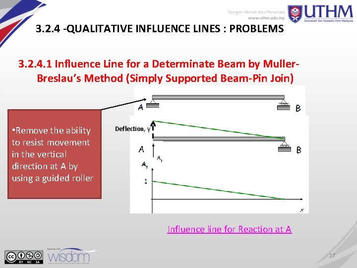
3. 2. 4 -QUALITATIVE INFLUENCE LINES : PROBLEMS 3. 2. 4. 1 Influence Line for a Determinate Beam by Muller. Breslau’s Method (Simply Supported Beam-Pin Join) • Remove the ability to resist movement in the vertical direction at A by using a guided roller Deflection, y Influence line for Reaction at A 17
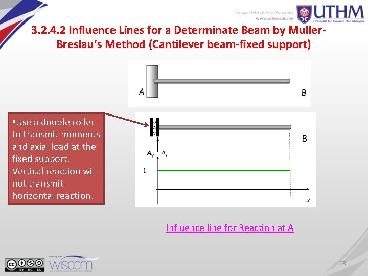
3. 2. 4. 2 Influence Lines for a Determinate Beam by Muller. Breslau’s Method (Cantilever beam-fixed support) • Use a double roller to transmit moments and axial load at the fixed support. Vertical reaction will not transmit horizontal reaction. Influence line for Reaction at A 18
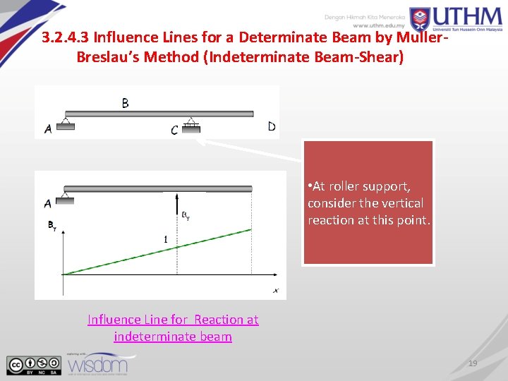
3. 2. 4. 3 Influence Lines for a Determinate Beam by Muller. Breslau’s Method (Indeterminate Beam-Shear) • At roller support, consider the vertical reaction at this point. Influence Line for Reaction at indeterminate beam 19
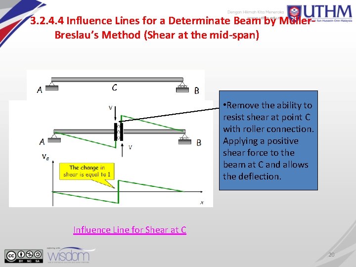
3. 2. 4. 4 Influence Lines for a Determinate Beam by Muller. Breslau’s Method (Shear at the mid-span) • Remove the ability to resist shear at point C with roller connection. Applying a positive shear force to the beam at C and allows the deflection. Influence Line for Shear at C 20

3. 2. 4. 5 Influence Lines for a Determinate Beam by Muller. Breslau’s Method (Shear at the cantilever beam) • A roller guide must be placed at C, the positive shear is applied. The left segment of the beam does not deflect due to fixed support. Influence Line for Shear at C 21
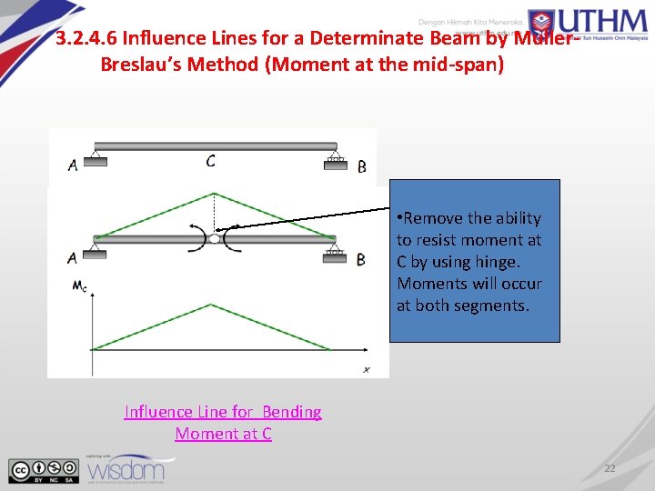
3. 2. 4. 6 Influence Lines for a Determinate Beam by Muller. Breslau’s Method (Moment at the mid-span) • Remove the ability to resist moment at C by using hinge. Moments will occur at both segments. Influence Line for Bending Moment at C 22

Ex : Draw the influence lines for the vertical reaction at D and the shear at E. 10 m 15 m If the change in shear at point E is equal to 1, find the shear value at points E and C. 23
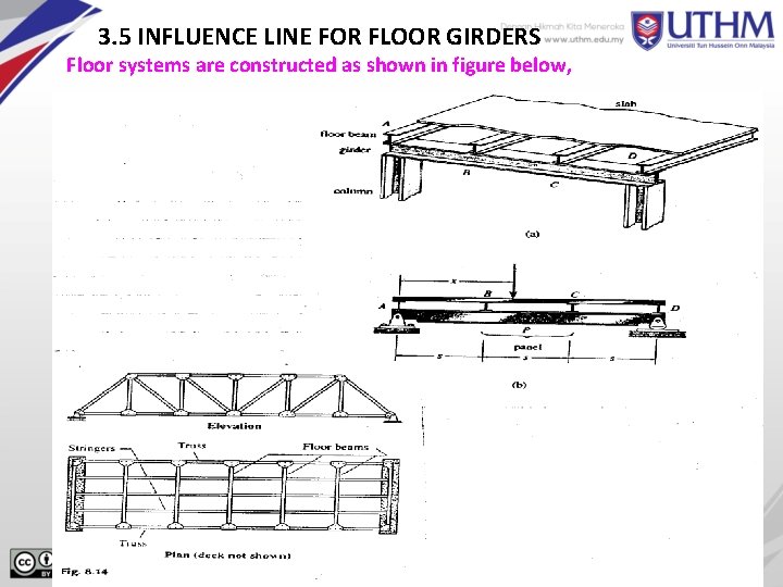
3. 5 INFLUENCE LINE FOR FLOOR GIRDERS Floor systems are constructed as shown in figure below, 24
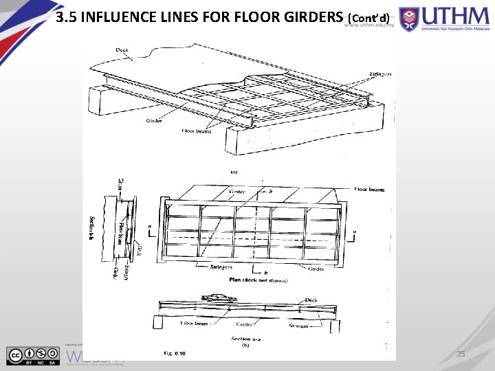
3. 5 INFLUENCE LINES FOR FLOOR GIRDERS (Cont’d) 25
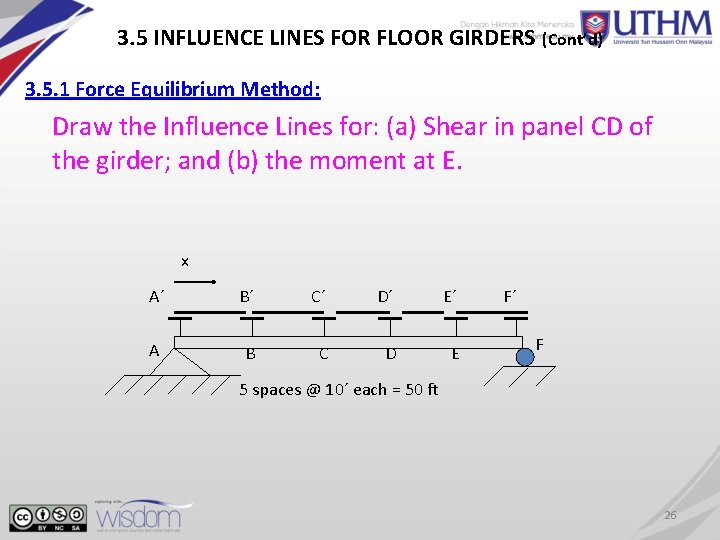
3. 5 INFLUENCE LINES FOR FLOOR GIRDERS (Cont’d) 3. 5. 1 Force Equilibrium Method: Draw the Influence Lines for: (a) Shear in panel CD of the girder; and (b) the moment at E. x A´ B´ C´ D´ E´ A B C D E F´ F 5 spaces @ 10´ each = 50 ft 26
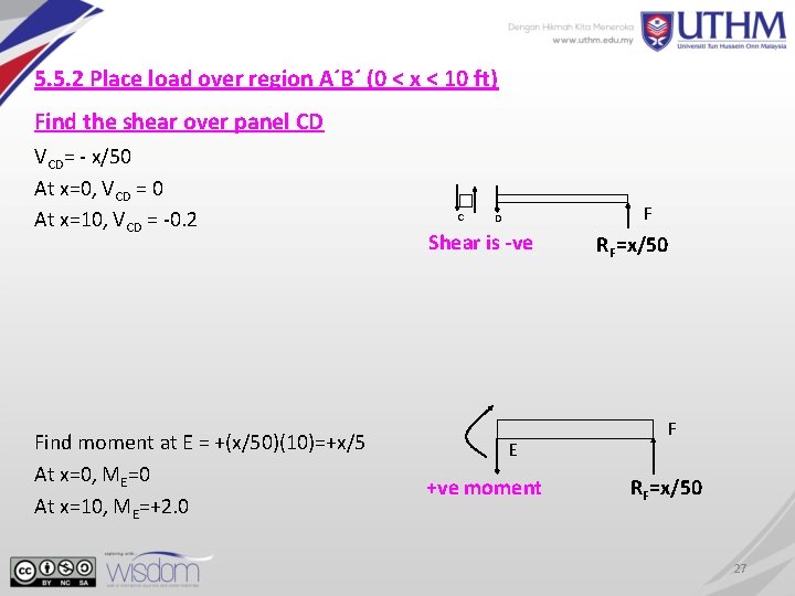
5. 5. 2 Place load over region A´B´ (0 < x < 10 ft) Find the shear over panel CD VCD= - x/50 At x=0, VCD = 0 At x=10, VCD = -0. 2 Find moment at E = +(x/50)(10)=+x/5 At x=0, ME=0 At x=10, ME=+2. 0 C F D Shear is -ve E +ve moment RF=x/50 F RF=x/50 27
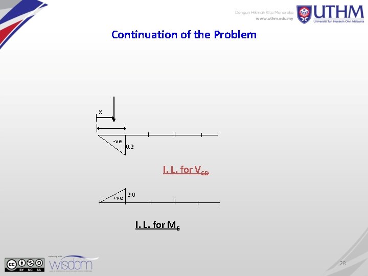
Continuation of the Problem x -ve 0. 2 I. L. for VCD +ve 2. 0 I. L. for ME 28
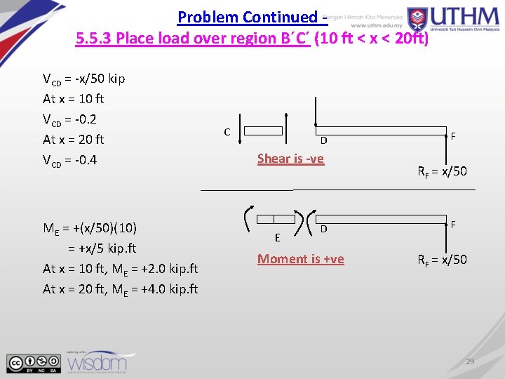
Problem Continued 5. 5. 3 Place load over region B´C´ (10 ft < x < 20 ft) VCD = -x/50 kip At x = 10 ft VCD = -0. 2 At x = 20 ft VCD = -0. 4 ME = +(x/50)(10) = +x/5 kip. ft At x = 10 ft, ME = +2. 0 kip. ft At x = 20 ft, ME = +4. 0 kip. ft C D Shear is -ve E D Moment is +ve F RF = x/50 29
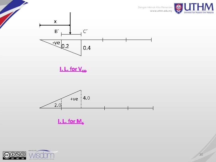
x B´ C´ -ve 0. 2 0. 4 I. L. for VCD 2. 0 +ve 4. 0 I. L. for ME 30
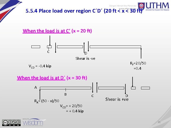
5. 5. 4 Place load over region C´D´ (20 ft < x < 30 ft) When the load is at C’ (x = 20 ft) C D Shear is -ve RF=20/50 =0. 4 VCD = -0. 4 kip When the load is at D´ (x = 30 ft) A B RA= (50 - x)/50 C D Shear is +ve VCD= + 20/50 = + 0. 4 kip 31
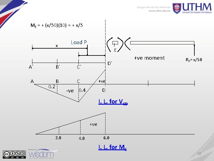
ME = + (x/50)(10) = + x/5 x Load P E A´ B´ C´ A B C 0. 2 D´ +ve moment RF= x/50 +ve -ve 0. 4 D I. L. for VCD +ve 2. 0 4. 0 6. 0 I. L. for ME 32
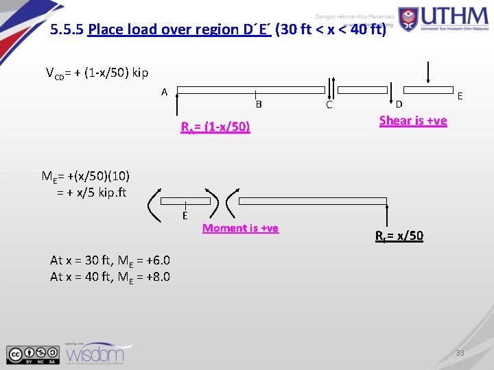
5. 5. 5 Place load over region D´E´ (30 ft < x < 40 ft) VCD= + (1 -x/50) kip A B RA= (1 -x/50) C D E Shear is +ve ME= +(x/50)(10) = + x/5 kip. ft E Moment is +ve RF= x/50 At x = 30 ft, ME = +6. 0 At x = 40 ft, ME = +8. 0 33
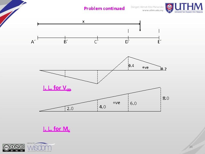
Problem continued x A´ B´ C´ D´ E´ 0. 4 +ve 0. 2 I. L. for VCD 2. 0 4. 0 +ve 6. 0 8. 0 I. L. for ME 34
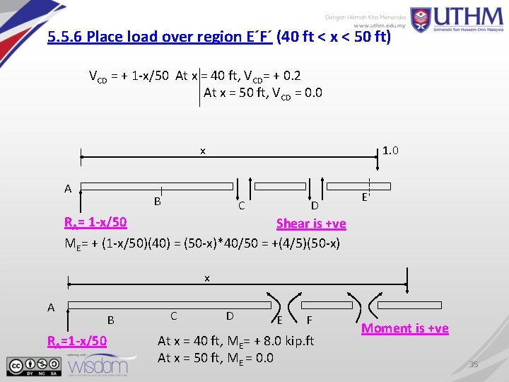
5. 5. 6 Place load over region E´F´ (40 ft < x < 50 ft) VCD = + 1 -x/50 At x = 40 ft, VCD= + 0. 2 At x = 50 ft, VCD = 0. 0 x A 1. 0 B C D E RA= 1 -x/50 Shear is +ve ME= + (1 -x/50)(40) = (50 -x)*40/50 = +(4/5)(50 -x) x A RA=1 -x/50 B C D E F At x = 40 ft, ME= + 8. 0 kip. ft At x = 50 ft, ME = 0. 0 Moment is +ve 35
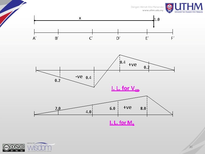
x A´ B´ 1. 0 C´ D´ E´ 0. 4 0. 2 -ve +ve F´ 0. 2 0. 4 I. L. for VCD 2. 0 4. 0 6. 0 +ve 8. 0 I. L. for ME 36
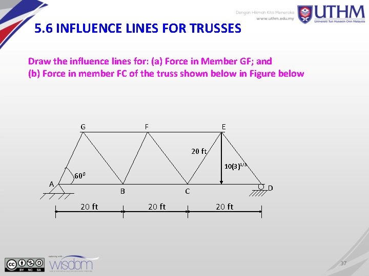
5. 6 INFLUENCE LINES FOR TRUSSES Draw the influence lines for: (a) Force in Member GF; and (b) Force in member FC of the truss shown below in Figure below G F E 20 ft 10(3)1/3 A 600 B 20 ft D C 20 ft 37
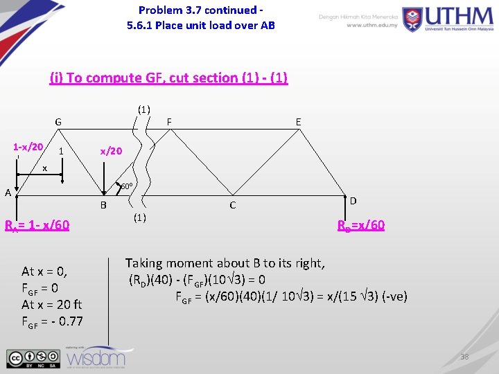
Problem 3. 7 continued 5. 6. 1 Place unit load over AB (i) To compute GF, cut section (1) - (1) G 1 -x/20 1 F E x/20 x 600 A B RA= 1 - x/60 At x = 0, FGF = 0 At x = 20 ft FGF = - 0. 77 (1) C D RD=x/60 Taking moment about B to its right, (RD)(40) - (FGF)(10 3) = 0 FGF = (x/60)(40)(1/ 10 3) = x/(15 3) (-ve) 38
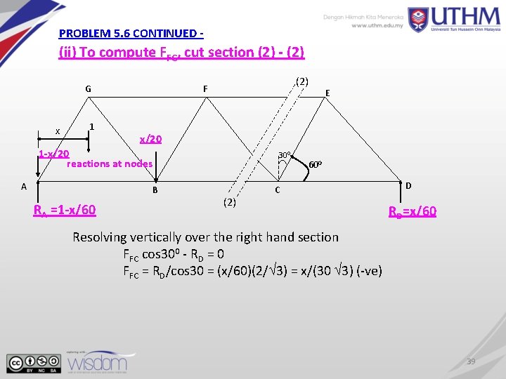
PROBLEM 5. 6 CONTINUED - (ii) To compute FFC, cut section (2) - (2) G x 1 (2) F x/20 1 -x/20 reactions at nodes A B RA =1 -x/60 E 300 (2) 600 C D RD=x/60 Resolving vertically over the right hand section FFC cos 300 - RD = 0 FFC = RD/cos 30 = (x/60)(2/ 3) = x/(30 3) (-ve) 39
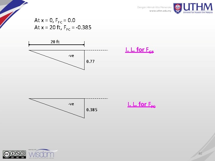
At x = 0, FFC = 0. 0 At x = 20 ft, FFC = -0. 385 20 ft -ve I. L. for FGF 0. 77 0. 385 I. L. for FFC 40
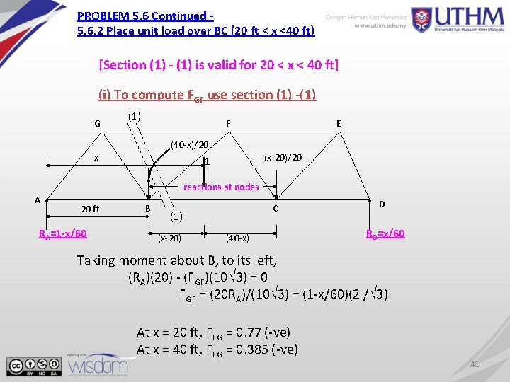
PROBLEM 5. 6 Continued 5. 6. 2 Place unit load over BC (20 ft < x <40 ft) [Section (1) - (1) is valid for 20 < x < 40 ft] (i) To compute FGF use section (1) -(1) G (1) F E (40 -x)/20 x (x-20)/20 1 reactions at nodes A 20 ft RA=1 -x/60 B C (1) (x-20) (40 -x) D RD=x/60 Taking moment about B, to its left, (RA)(20) - (FGF)(10 3) = 0 FGF = (20 RA)/(10 3) = (1 -x/60)(2 / 3) At x = 20 ft, FFG = 0. 77 (-ve) At x = 40 ft, FFG = 0. 385 (-ve) 41
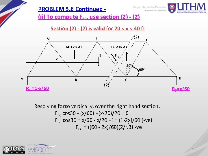
PROBLEM 5. 6 Continued (ii) To compute FFC, use section (2) - (2) Section (2) - (2) is valid for 20 < x < 40 ft G (2) F (40 -x)/20 (x-20)/20 1 x FFC 300 A B RA =1 -x/60 E (2) 600 C D RD=x/60 Resolving force vertically, over the right hand section, FFC cos 30 - (x/60) +(x-20)/20 = 0 FFC cos 30 = x/60 - x/20 +1= (1 -2 x)/60 (-ve) FFC = ((60 - 2 x)/60)(2/ 3) -ve 42
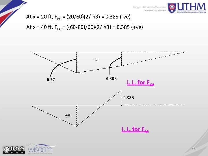
At x = 20 ft, FFC = (20/60)(2/ 3) = 0. 385 (-ve) At x = 40 ft, FFC = ((60 -80)/60)(2/ 3) = 0. 385 (+ve) -ve 0. 385 0. 77 I. L. for FGF 0. 385 -ve I. L. for FFC 43
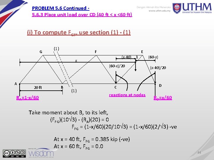
PROBLEM 5. 6 Continued 5. 6. 3 Place unit load over CD (40 ft < x <60 ft) (i) To compute FGF, use section (1) - (1) G (1) F E (x-40) x 1 (60 -x)/20 A 20 ft RA=1 -x/60 B (1) C reactions at nodes (60 -x) (x-40)/20 D RD=x/60 Take moment about B, to its left, (FFG)(10 3) - (RA)(20) = 0 FFG = (1 -x/60)(20/10 3) = (1 -x/60)(2/ 3) -ve At x = 40 ft, FFG = 0. 385 kip (-ve) At x = 60 ft, FFG = 0. 0 44
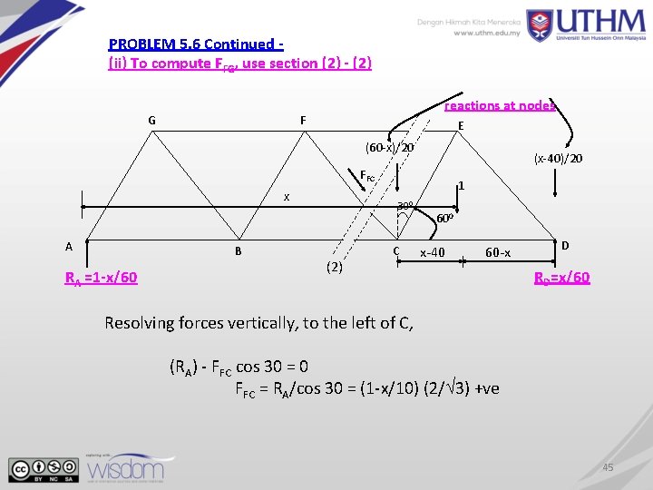
PROBLEM 5. 6 Continued (ii) To compute FFG, use section (2) - (2) G reactions at nodes F E (60 -x)/20 (x-40)/20 FFC x A B RA =1 -x/60 1 300 (2) C 600 x-40 60 -x D RD=x/60 Resolving forces vertically, to the left of C, (RA) - FFC cos 30 = 0 FFC = RA/cos 30 = (1 -x/10) (2/ 3) +ve 45
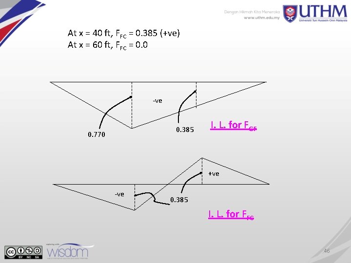
At x = 40 ft, FFC = 0. 385 (+ve) At x = 60 ft, FFC = 0. 0 -ve 0. 385 0. 770 I. L. for FGF +ve -ve 0. 385 I. L. for FFC 46
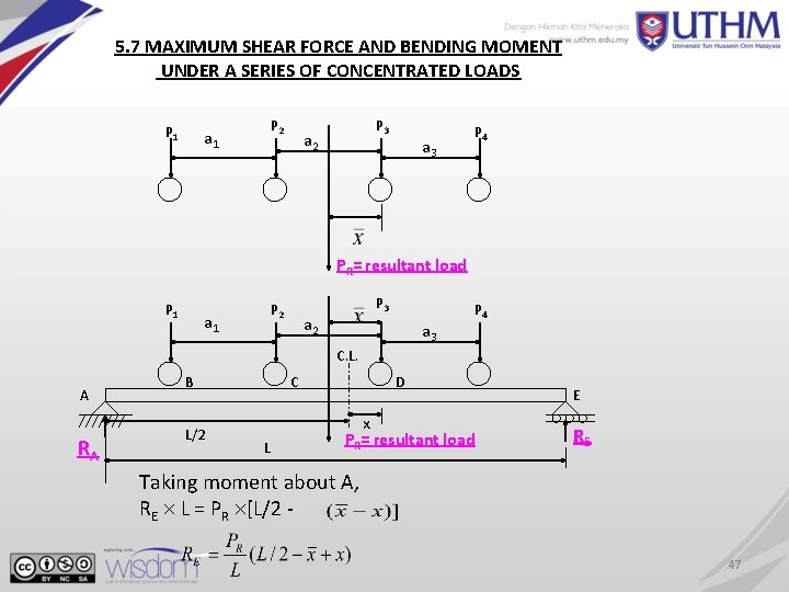
5. 7 MAXIMUM SHEAR FORCE AND BENDING MOMENT UNDER A SERIES OF CONCENTRATED LOADS P 1 P 2 a 1 P 3 a 2 a 3 P 4 PR= resultant load P 1 P 2 a 1 P 3 a 2 a 3 P 4 C. L. A RA B L/2 C L D x PR= resultant load E RE Taking moment about A, RE L = PR [L/2 47
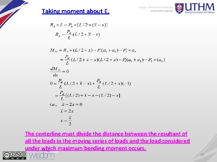
Taking moment about E, The centerline must divide the distance between the resultant of all the loads in the moving series of loads and the load considered under which maximum bending moment occurs. 48
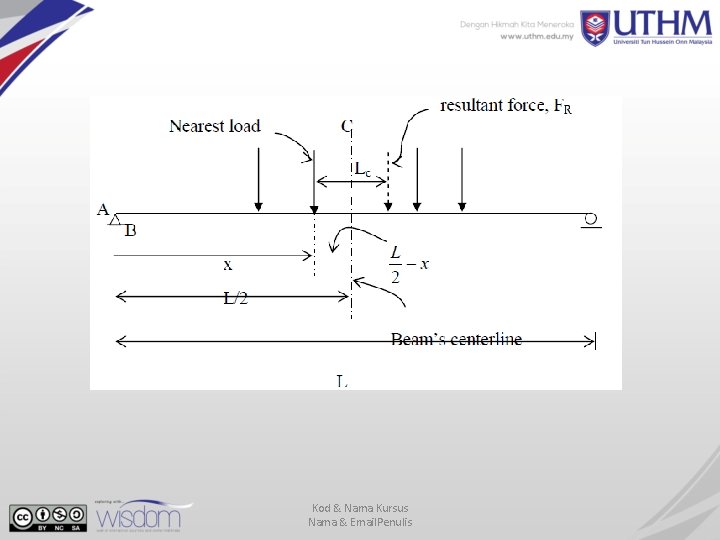
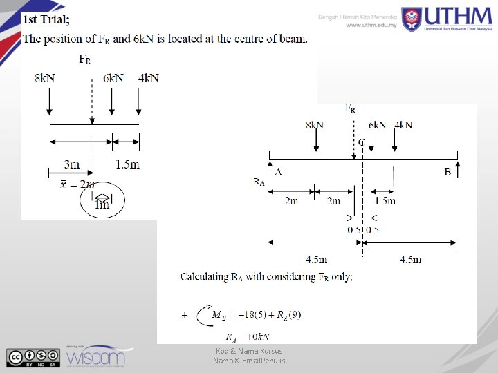
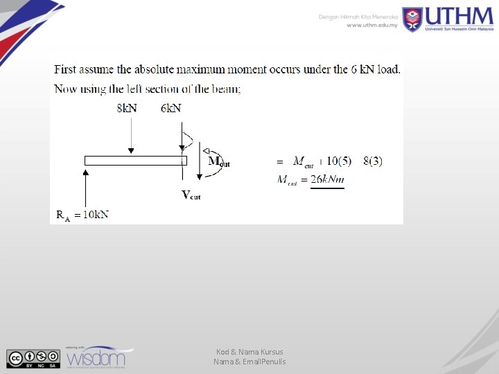
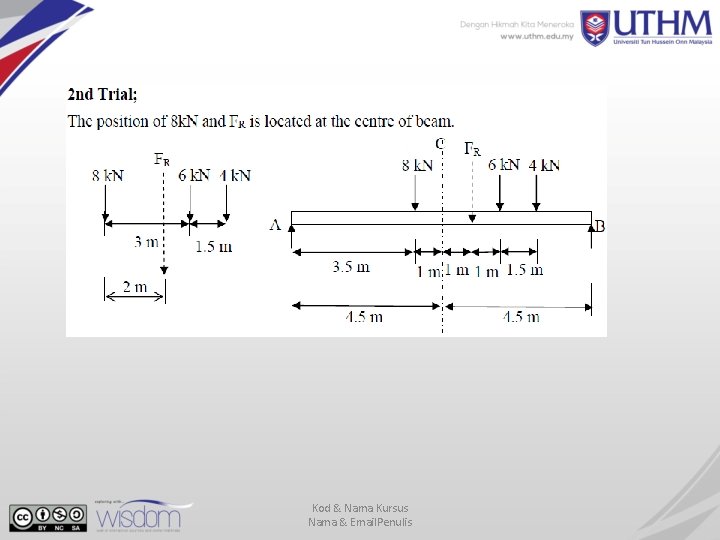
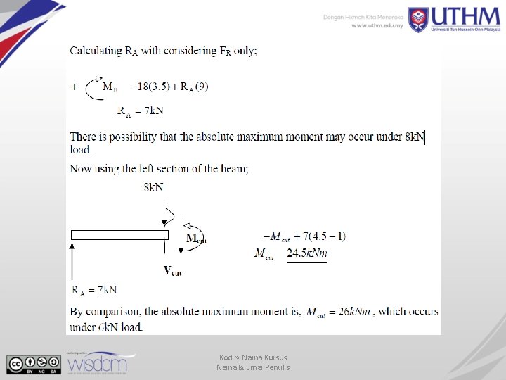
ABSOLUTE MAXIMUM SHEAR AND MOMENT • Maximum moment on the beam subjected to the moving load is located on the beam’s centreline between the resultant force and the nearest point. • Absolute maximum moment in simply supported beam occurs under one of the concentrated forces series. • This principle will have to be applied to each load in the series and the corresponding maximum moment is computed. • By comparison, the largest moment is the absolute maximum.
Kod & Nama Kursus Nama & Email. Penulis
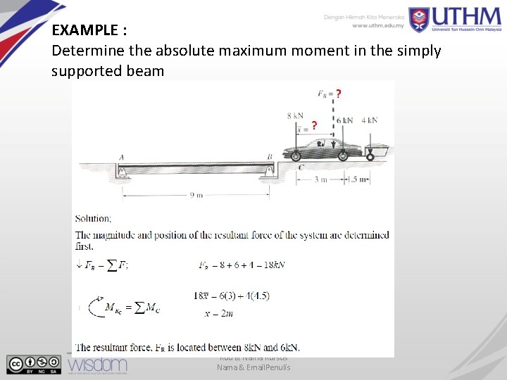
EXAMPLE : Determine the absolute maximum moment in the simply supported beam Kod & Nama Kursus Nama & Email. Penulis
Kod & Nama Kursus Nama & Email. Penulis
Kod & Nama Kursus Nama & Email. Penulis
Kod & Nama Kursus Nama & Email. Penulis
Kod & Nama Kursus Nama & Email. Penulis
THANK YOU
- Slides: 56