
BMT 414 Pacemakers Dr Ali Saad Biomedical Engineering
BMT 414 Pacemakers Dr. Ali Saad, Biomedical Engineering Dept. College of applied medical sciences King Saud University 1

2 2

3

Cardiac Conduction System 4

Cardiac depolarization 5
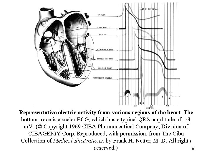
Representative electric activity from various regions of the heart. The bottom trace is a scalar ECG, which has a typical QRS amplitude of 1 -3 m. V. (© Copyright 1969 CIBA Pharmaceutical Company, Division of CIBAGEIGY Corp. Reproduced, with permission, from The Ciba Collection of Medical Illustrations, by Frank H. Netter, M. D. All rights reserved. ) 6
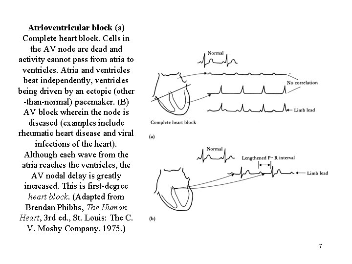
Atrioventricular block (a) Complete heart block. Cells in the AV node are dead and activity cannot pass from atria to ventricles. Atria and ventricles beat independently, ventricles being driven by an ectopic (other -than-normal) pacemaker. (B) AV block wherein the node is diseased (examples include rheumatic heart disease and viral infections of the heart). Although each wave from the atria reaches the ventricles, the AV nodal delay is greatly increased. This is first-degree heart block. (Adapted from Brendan Phibbs, The Human Heart, 3 rd ed. , St. Louis: The C. V. Mosby Company, 1975. ) 7
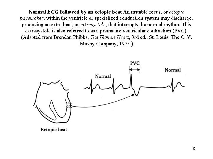
Normal ECG followed by an ectopic beat An irritable focus, or ectopic pacemaker, within the ventricle or specialized conduction system may discharge, producing an extra beat, or extrasystole, that interrupts the normal rhythm. This extrasystole is also referred to as a premature ventricular contraction (PVC). (Adapted from Brendan Phibbs, The Human Heart, 3 rd ed. , St. Louis: The C. V. Mosby Company, 1975. ) 8
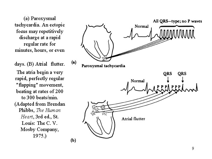
(a) Paroxysmal tachycardia. An ectopic focus may repetitively discharge at a rapid regular rate for minutes, hours, or even days. (B) Atrial flutter. The atria begin a very rapid, perfectly regular "flapping" movement, beating at rates of 200 to 300 beats/min. (Adapted from Brendan Phibbs, The Human Heart, 3 rd ed. , St. Louis: The C. V. Mosby Company, 1975. ) 9
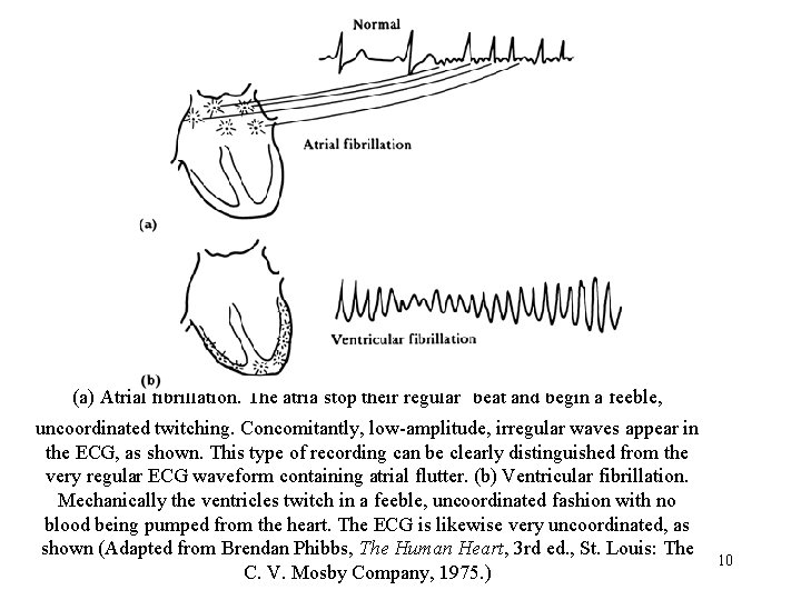
(a) Atrial fibrillation. The atria stop their regular beat and begin a feeble, uncoordinated twitching. Concomitantly, low-amplitude, irregular waves appear in the ECG, as shown. This type of recording can be clearly distinguished from the very regular ECG waveform containing atrial flutter. (b) Ventricular fibrillation. Mechanically the ventricles twitch in a feeble, uncoordinated fashion with no blood being pumped from the heart. The ECG is likewise very uncoordinated, as shown (Adapted from Brendan Phibbs, The Human Heart, 3 rd ed. , St. Louis: The C. V. Mosby Company, 1975. ) 10
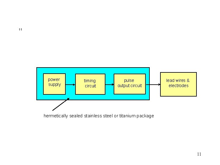
11 power supply timing circuit pulse output circuit lead wires & electrodes hermetically sealed stainless steel or titanium package 11

Block diagram of an asynchronous cardiac pacemaker 12
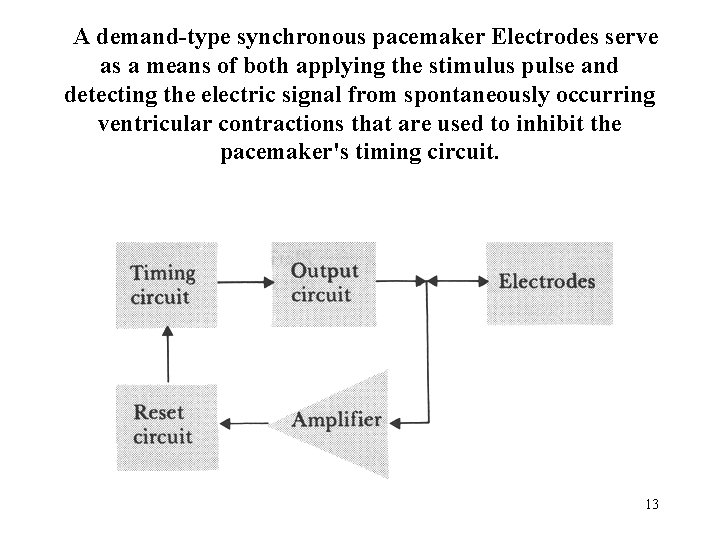
A demand-type synchronous pacemaker Electrodes serve as a means of both applying the stimulus pulse and detecting the electric signal from spontaneously occurring ventricular contractions that are used to inhibit the pacemaker's timing circuit. 13
Demand Synchronous Pacing (cont. ) n n n after each stimulus, timing circuit resets, and waits a certain time interval, T (1 sec). if amplifier detects naturally occurring R-wave during this interval, timing circuit reset again. timing circuit keeps resetting with each naturally occurring beat as long as it occurs within T seconds of previous beat. if no naturally occurring beat occurs after T seconds, output circuit stimulates. useful for bradycardia (slow HR). 14
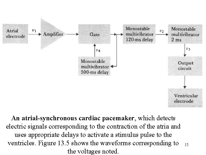
An atrial-synchronous cardiac pacemaker, which detects electric signals corresponding to the contraction of the atria and uses appropriate delays to activate a stimulus pulse to the ventricles. Figure 13. 5 shows the waveforms corresponding to the voltages noted. 15
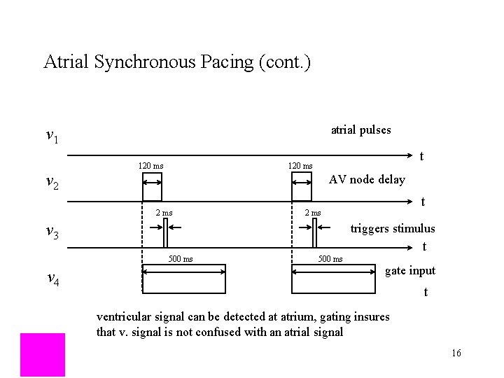
Atrial Synchronous Pacing (cont. ) atrial pulses v 1 v 2 t 120 ms AV node delay 2 ms v 3 triggers stimulus t 500 ms v 4 t 2 ms 500 ms gate input t ventricular signal can be detected at atrium, gating insures that v. signal is not confused with an atrial signal 16
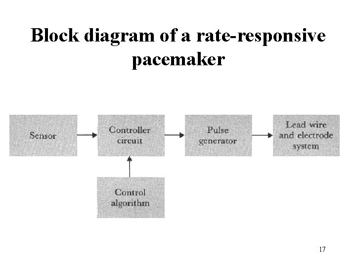
Block diagram of a rate-responsive pacemaker 17

18

Piezoelectric element bonded to the inside of the pacemaker can. Body motion causes pressure fluctuations which cause the can to deflect which bends the sensor to produce a voltage. The leads from the piezoelectric sensor are connected to the pacemaker electronics. This is one possible layout for the pacemaker 19 components.
The three-letter pacemaker coding system was recommended by ICHD in 1974 and became the first widely adopted pacemaker code. It was simple and easy to use and it only contained three letters. The first letter designates the chamber(s) paced: ventricle (V), atrium (A), or both (D for double). The second letter designates the chamber(s) sensed. The third letter designates the mode of response(s): T = triggered, I = inhibited, D = double, O = none. The code was revised in 1981 to accommodate new functionalities of pacemakers. 20
A logical diagram of relationship between rhythm disturbances and therapeutic pacing modes for selecting the proper pacing mode. From Schaldach, M. M. 1992. Electrotherapy of the heart. Berlin: Springer–Verlag. 21

DDD Pacemaker n n combines: • demand synchronous • atrial synchronous • ventricular synchronous atrial sensor detects natural or stimulated atrial contraction, then triggers ventricles if no naturally occurring ventricular pulse is detected within TAV = 120 ms. ventricular sensor detects natural or stimulated ventricular contraction, then triggers atria if no naturally occurring atrial pulse is detected within TVA = 700 ms. 22

Evolution of implantable pacemaker technology 23

Implanted pacemaker 24
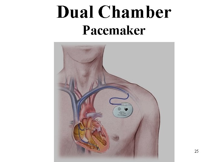
Dual Chamber Pacemaker 25
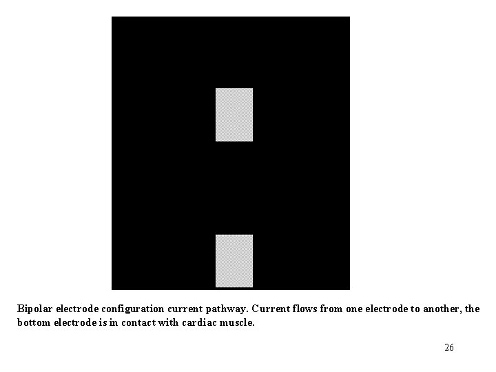
Bipolar electrode configuration current pathway. Current flows from one electrode to another, the bottom electrode is in contact with cardiac muscle. 26
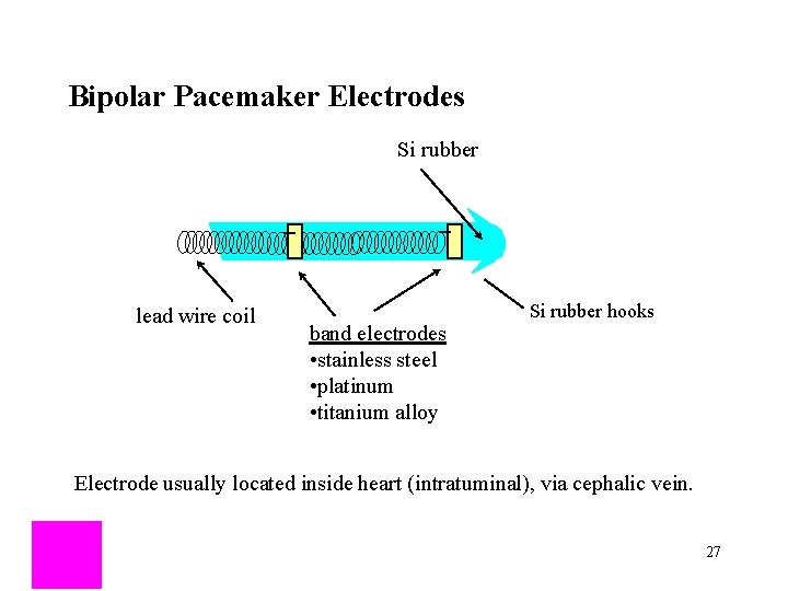
Bipolar Pacemaker Electrodes Si rubber lead wire coil band electrodes • stainless steel • platinum • titanium alloy Si rubber hooks Electrode usually located inside heart (intratuminal), via cephalic vein. 27
Unipolar electrode configuration current pathway. Only the cathode electrode is in contact with myocardium with unipolar stimulation, the other (anode) electrode often is the case of the pulse generator, which is some distance from the heart 28
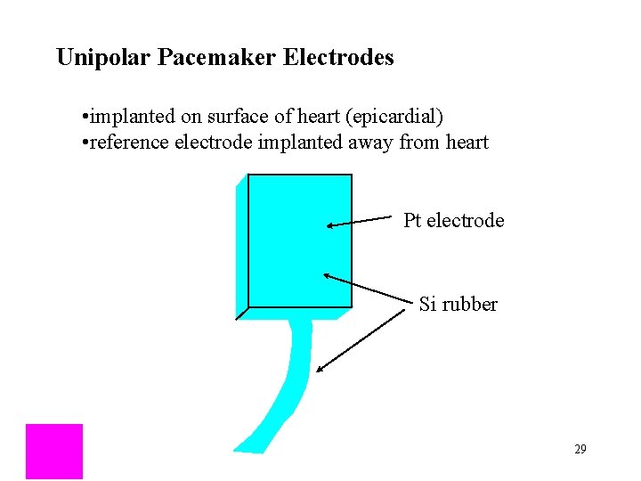
Unipolar Pacemaker Electrodes • implanted on surface of heart (epicardial) • reference electrode implanted away from heart Pt electrode Si rubber 29
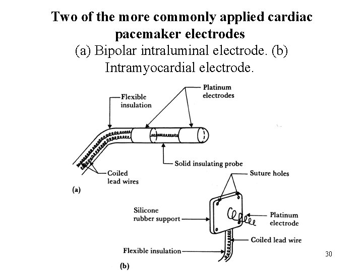
Two of the more commonly applied cardiac pacemaker electrodes (a) Bipolar intraluminal electrode. (b) Intramyocardial electrode. 30
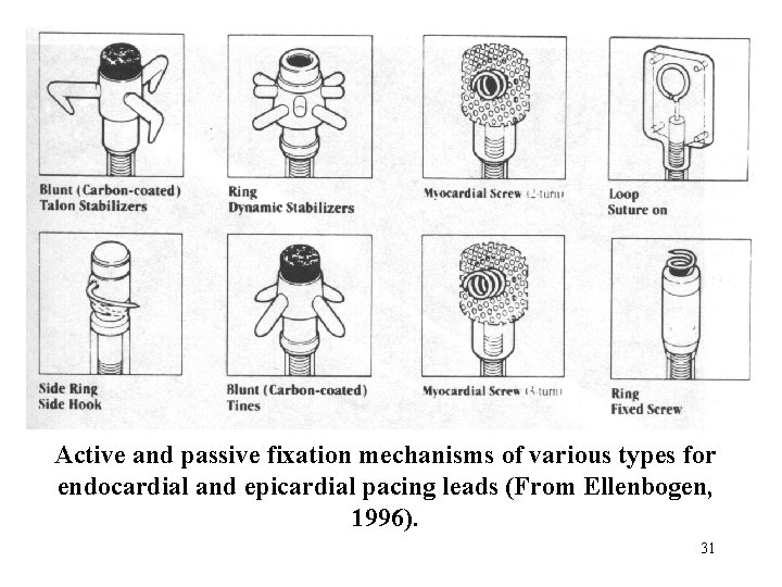
Active and passive fixation mechanisms of various types for endocardial and epicardial pacing leads (From Ellenbogen, 1996). 31
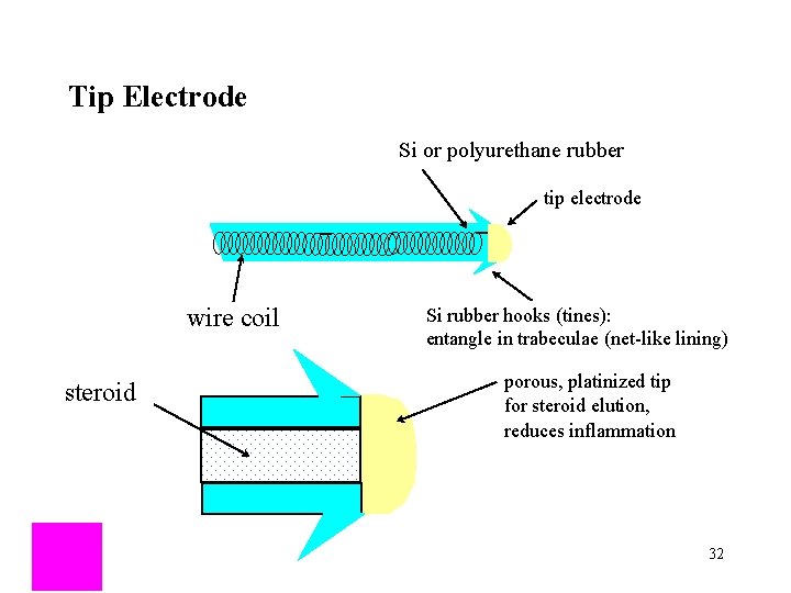
Tip Electrode Si or polyurethane rubber tip electrode wire coil steroid Si rubber hooks (tines): entangle in trabeculae (net-like lining) porous, platinized tip for steroid elution, reduces inflammation 32
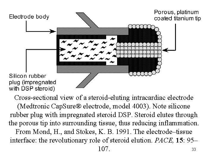
Cross-sectional view of a steroid-eluting intracardiac electrode (Medtronic Cap. Sure® electrode, model 4003). Note silicone rubber plug with impregnated steroid DSP. Steroid elutes through the porous tip into surrounding tissue, thus reducing inflammation. From Mond, H. , and Stokes, K. B. 1991. The electrode–tissue interface: the revolutionary role of steroid elution. PACE, 15: 95– 33 107.
Threshold evolution after implantation. (a) Once an electrode is placed against or within sensitive tissue, local reaction causes enlargement of its surface area as the virtual electrode is formed. As chronicity is reached, the virtual electrode is smaller than early after implant and the threshold decreases and is stabilized. (b) Steroid-eluting electrodes have produced a distinct reduction in stimulation threshold acutely and chronically. Sensing characteristics have also improved. This figure compares similar solid tips, without steroid and steroid-eluting electrodes. The increase in stimulation threshold for the steroid electrode early after implant is much reduced and the long-term stable threshold for both is characteristic (Modified from 34 Furman et al. , 1993).
The current strength (I)–duration (d) curve: for canine muscle: A = atrium, V = ventricle (modified from Geddes 1984). 35
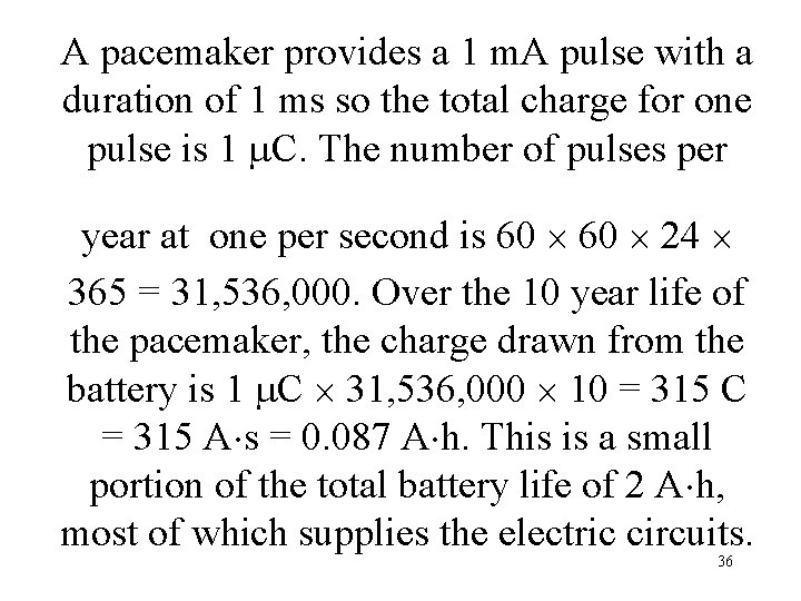
A pacemaker provides a 1 m. A pulse with a duration of 1 ms so the total charge for one pulse is 1 C. The number of pulses per year at one per second is 60 24 365 = 31, 536, 000. Over the 10 year life of the pacemaker, the charge drawn from the battery is 1 C 31, 536, 000 10 = 315 C = 315 A s = 0. 087 A h. This is a small portion of the total battery life of 2 A h, most of which supplies the electric circuits. 36
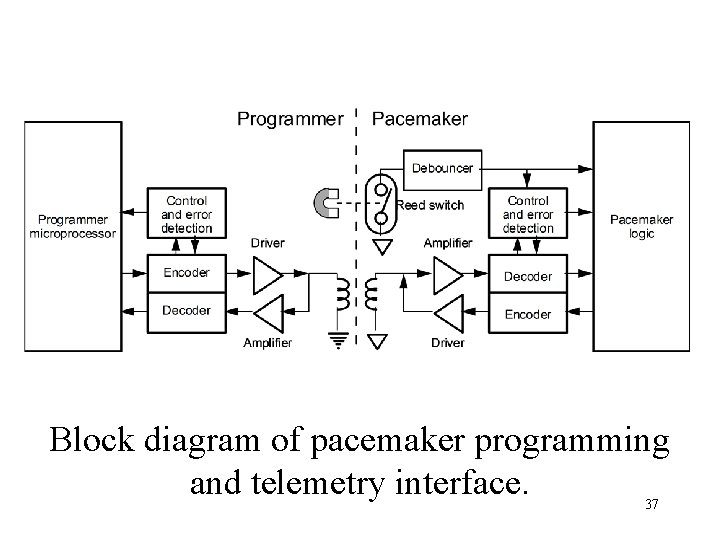
Block diagram of pacemaker programming and telemetry interface. 37

Timing and Output Circuits n n n Asynchronous: runs at a fixed pacing rate, set by technician (70 -90 BPM): these are no longer used since if a stimulus is applied during the T-wave of a normal beat, can get v. fibrillation. Synchronous: uses feedback from ECG and/or other sources to determine pacing rate (60 -150 BPM). output circuit: n constant current pulses: 8 -10 m. A, 1 -1. 2 ms duration n constant voltage pulses: 5 -5. 5 V, 500 -600 s duration 38 38
Lead Wires and Electrodes n n n Must be able to withstand constant bending due to beating of the heart (35 million beats per year). Must be biocompatable, tissues can be very corrosive The two above criteria are satisfied via interwound helical coils embedded in silicon or polyurethane rubber. 39 39
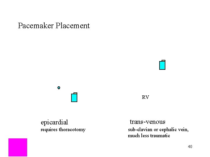
Pacemaker Placement RV epicardial requires thoracotomy trans-venous sub-clavian or cephalic vein, much less traumatic 40
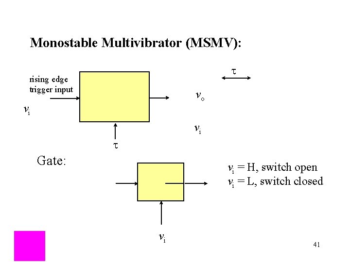
Monostable Multivibrator (MSMV): t rising edge trigger input vo vi vi t Gate: vi = H, switch open vi = L, switch closed vi 41
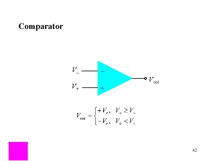
Comparator V_ V+ _ + Vout 42
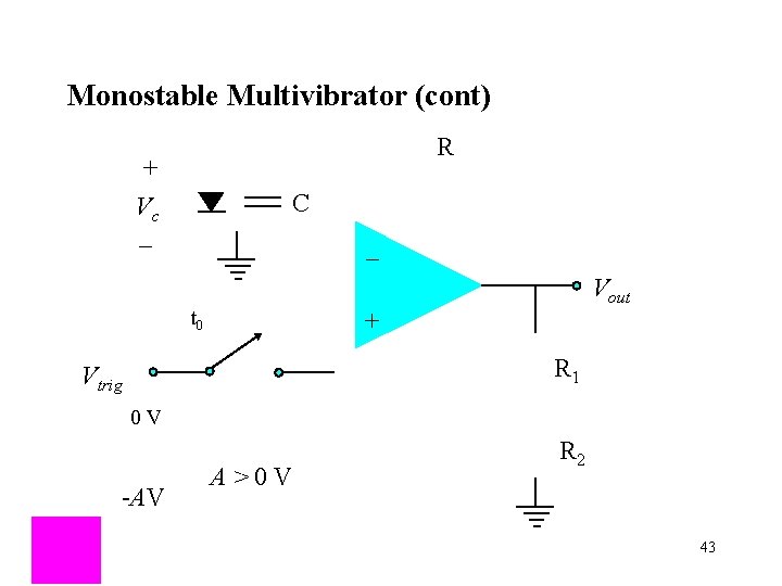
Monostable Multivibrator (cont) R + Vc _ C _ Vout t 0 + R 1 Vtrig 0 V -AV A > 0 V R 2 43
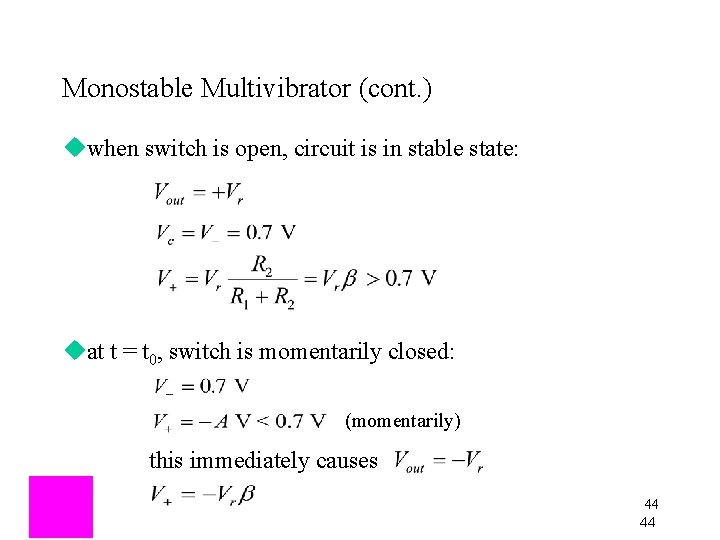
Monostable Multivibrator (cont. ) uwhen switch is open, circuit is in stable state: uat t = t 0, switch is momentarily closed: (momentarily) this immediately causes 44 44
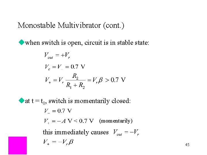
Monostable Multivibrator (cont. ) uwhen switch is open, circuit is in stable state: uat t = t 0, switch is momentarily closed: (momentarily) this immediately causes 45
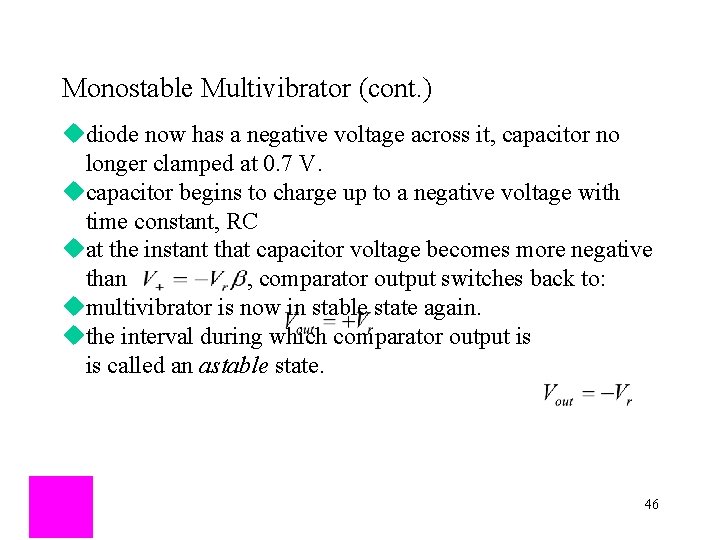
Monostable Multivibrator (cont. ) udiode now has a negative voltage across it, capacitor no longer clamped at 0. 7 V. ucapacitor begins to charge up to a negative voltage with time constant, RC uat the instant that capacitor voltage becomes more negative than , comparator output switches back to: umultivibrator is now in stable state again. uthe interval during which comparator output is is called an astable state. 46
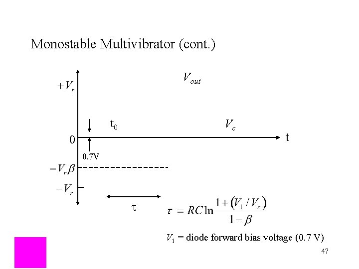
Monostable Multivibrator (cont. ) Vout t 0 Vc 0 t 0. 7 V t V 1 = diode forward bias voltage (0. 7 V) 47
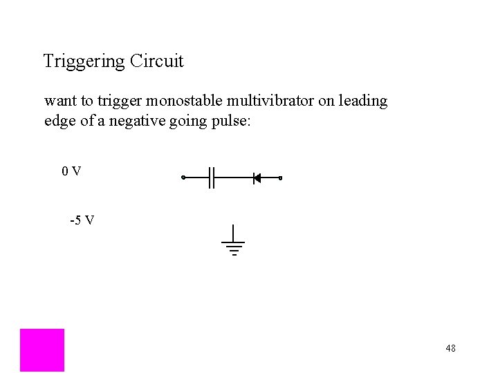
Triggering Circuit want to trigger monostable multivibrator on leading edge of a negative going pulse: 0 V -5 V 48
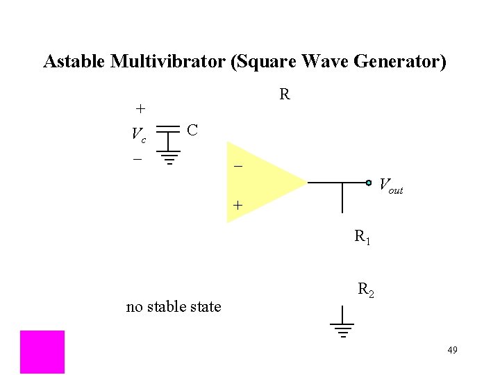
Astable Multivibrator (Square Wave Generator) + Vc _ R C _ Vout + R 1 no stable state R 2 49
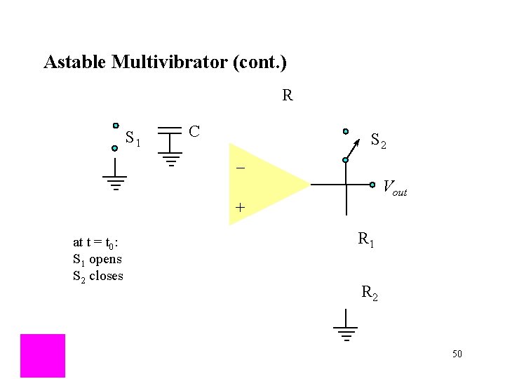
Astable Multivibrator (cont. ) R S 1 C _ S 2 Vout + at t = t 0: S 1 opens S 2 closes R 1 R 2 50
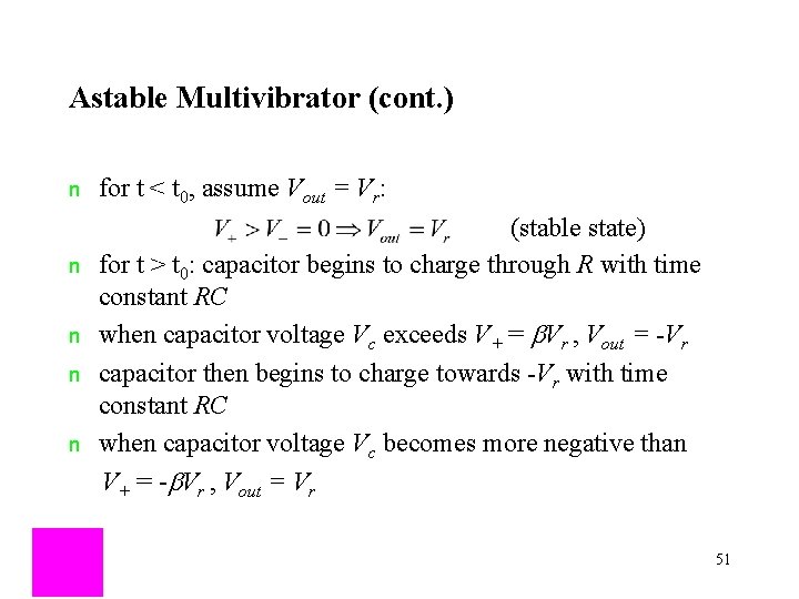
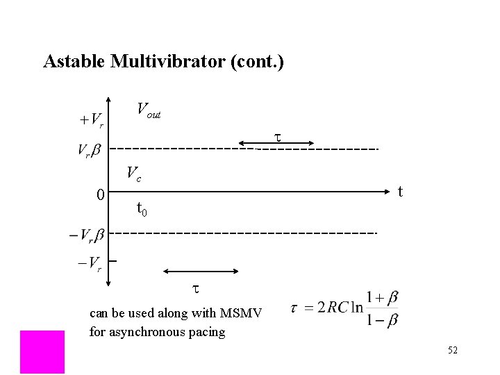
Astable Multivibrator (cont. ) n for t < t 0, assume Vout = Vr: (stable state) for t > t 0: capacitor begins to charge through R with time constant RC when capacitor voltage Vc exceeds V+ = b. Vr , Vout = -Vr capacitor then begins to charge towards -Vr with time constant RC when capacitor voltage Vc becomes more negative than V+ = -b. Vr , Vout = Vr n n 51
Astable Multivibrator (cont. ) Vout t Vc 0 t t 0 t can be used along with MSMV for asynchronous pacing 52
Operational Amplifiers (Op Amps) output: inputs: I = 0 _ + 53
Constant Current Source R R _ + R R + _ 54
Constant Current Source (cont. ) R R _ + R R + _ or 55
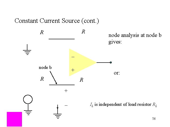
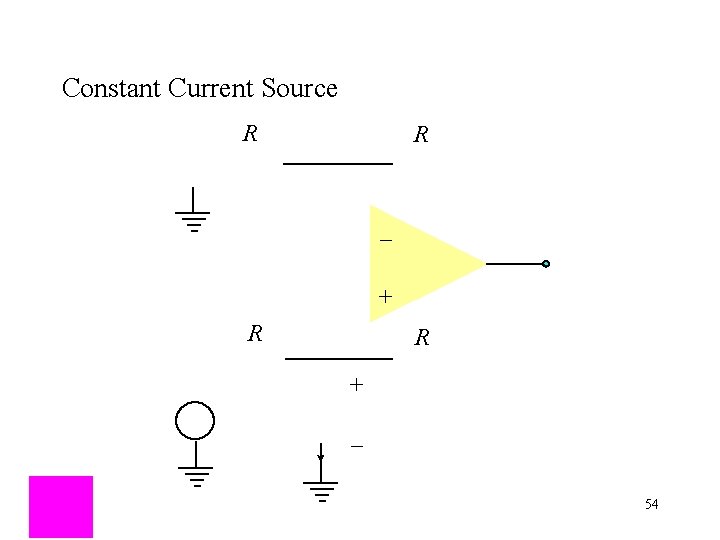
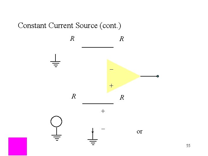
Constant Current Source (cont. ) R R node analysis at node b gives: _ node b + R or: R + _ IL is independent of load resistor RL 56
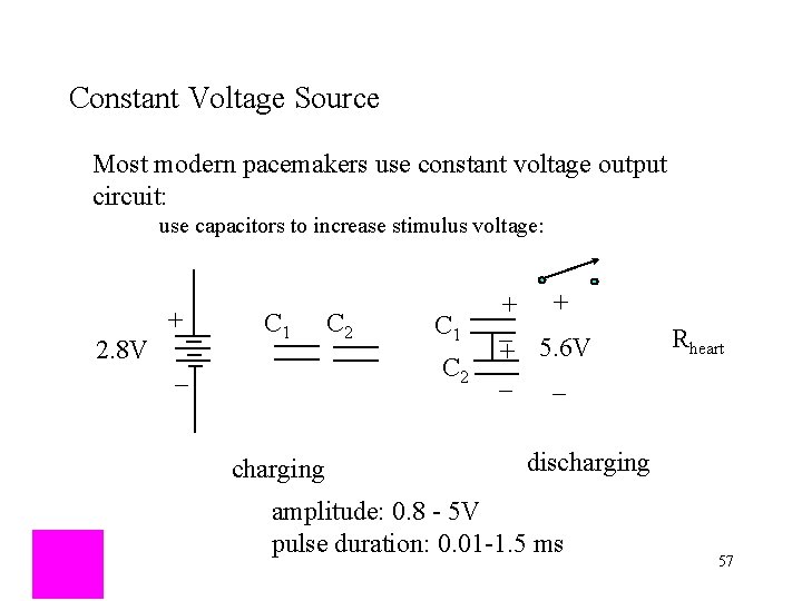
Constant Voltage Source Most modern pacemakers use constant voltage output circuit: use capacitors to increase stimulus voltage: 2. 8 V + C 1 C 2 _ charging + + _ + 5. 6 V _ _ Rheart discharging amplitude: 0. 8 - 5 V pulse duration: 0. 01 -1. 5 ms 57
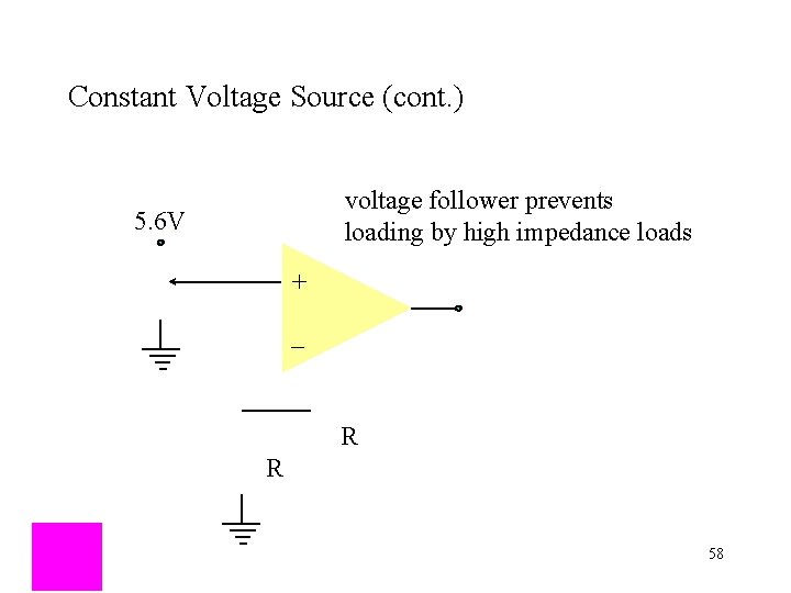
Constant Voltage Source (cont. ) voltage follower prevents loading by high impedance loads 5. 6 V + _ R R 58
- Slides: 58