Blue Pink 45 Ohms Blue Yellow 45 Ohms

Blue – Pink: 45 Ohms Blue – Yellow: 45 Ohms Blue – Orange: 45 Ohms Blue – Red: 23 Ohms This style is common in smaller unipolar motors. All of the common coil wires are tied together internally and brought out as a 5 th wire. This motor can only be driven as a unipolar motor. Pink – Yellow: 45 Ohms Pink – Orange: 45 Ohms Pink – Red: 23 Ohms Yellow – Orange: 45 Ohms Yellow – Red: 23 Ohms https: //learn. adafruit. com/allabout-stepper-motors/types-ofsteppers Orange – Red: 23 Ohms 23 Ω Orange (4) 23 Ω Pink (2) RED 46 Ω Yellow (3) Blue (1) 23 Ω RED Taking path of least resistance, one sees that 46 Ohms between any of the 4 wires e. g. red and blue arrows show paths

1. 2. 3. 4. 5. 6. 7. 8. Coil 1 and 2 Coil 2 and 3 Coil 3 and 4 Coil 4 and 1 Coil 1 Motor BLU PNK YLW ORG IN 1 IN 2 IN 3 IN 4 Board IN 1 BLK IN 2 WHT IN 3 GRY IN 4 PUR Arduino 12 11 10 9 BLK WHT GRY PUR
 Pink +5 Coil 2 STEP 4 Pink")
STEP 1 4 phase (because 4 coils) Pink +5 Coil 2 STEP 4 Pink GND Coil 2 Yellow coil: ON Pink coil: ON Orange coil: ON GND Orange Coil 1 +5 Coil 1 Yellow Coil 3 STEP 2 Pink +5 Coil 2 GND +5 +5 Orange coil: ON Yellow Coil 3 +5 GND Pink coil: ON +5 Orange Coil 1 Blue Coil 4 +5 STEP 6 Yellow Coil 3 +5 Blue Coil 4 +5 Pink +5 Coil 2 +5 GND STEP 5 Blue Coil 4 Pink GNDCoil 2 Orange Coil 1 STEP 3 Yellow Coil 3 Blue Coil 4 GND Coil 2 Yellow coil: ON Orange Coil 1 Yellow Coil 3 GND Blue Coil 4 +5 +5 Pink coil: ON Blue coil: ON Orange Coil 1 Yellow Coil 3 +5 Blue Coil 4 GND

STEP 6 Pink GND Coil 2 +5 Pink coil: ON Blue coil: ON Orange Coil 1 Yellow Coil 3 STEP 7 +5 +5 Blue Coil 4 GND Pink Coil 2 Blue coil: ON +5 Orange Coil 1 STEP 8 +5 GND Pink Coil 2 Yellow Coil 3 +5 Blue Coil 4 GND Blue coil: ON Orange Coil 1 Yellow Coil 3 Blue Coil 4 +5 GND

https: //components 101. com/motors/28 byj-48 -stepper-motor IN 4 IN 3 IN 2 IN 1 D 4 D 2 D 1 D 0 0111 (7) 0111 0011 1001 1100 1110 0011 (3) 1011 (11) 1001 (9) 1101 (13) 1100 (12) 1110 (14) 0110 (6)

Extreme NXT pg. 248 -249 D 0 D 2 D 3 Coils are in pairs: - Yellow and Black - Orange and Brown Members of a pair are never turned on at the same time because this is a unipolar device. It takes 4 steps before the pattern repeats 5 V (1) 5 V 5 V Active 5 V 5 V GND GND 0011=3 1001=9 0110=6 1100=12 D 3 -D 2 -D 1 -D 0 (2) 5 V 5 V Active D 1 (3) 5 V Active GND 5 V 5 V GND 5 V Active GND 5 V 5 V (4) 5 V
 and")
D 0 D 1 D 2 D 3 Pair 1: Yellow (IN 1) and Black (IN 2) Pair 2: Orange (IN 3) and Brown (IN 4) Motor BLU PNK YLW ORG IN 1 IN 2 IN 3 IN 4 Board IN 1 BLK IN 2 WHT IN 3 GRY IN 4 PUR Arduino 12 11 10 9 Pair 1: Pink (IN 1) and Orange (IN 2) Pair 2: Yellow (IN 3) and Blue (IN 4) BLK WHT GRY PUR

http: //www. extremenxt. com/stepper. html Maybe this website is the errata; it differs from book)

D 0 D 2 D 3 D 1 1001=9 0011=3 0110=6 1100=12 D 3 -D 2 -D 1 -D 0 Step D 0 (LSB) D 2 1 2 3 5 V Pink 0 V 5 V Yellow 0 V 5 V D 3 (MSB) Blue D 1 4 0 V 5 V Orange 0 V D 3 -D 2 -D 1 -D 0
 5 V 5 V (2) 5 V 5")
Extreme NXT Diagram 5 V (1) 5 V 5 V (2) 5 V 5 V Active 5 V 5 V GND 5 V 5 V 5 V (4) 5 V Active Active GND 5 V 5 V GND GND 5 V (3) GND P. Oh Modified Diagram (for NXT and PCF 8574 5 V (1) 5 V 5 V Active Pink GND Orange GND Yellow Blue 5 V 5 V 5 V Active 5 V (2) 5 V Pink 5 V Orange GND Yellow Blue GND (3) 5 V Active GND Pink 5 V Orange 5 V Yellow Blue GND 5 V Active GND 5 V 5 V Pink Orange Yellow Blue (4) 5 V

Pink Orange Yellow Blue
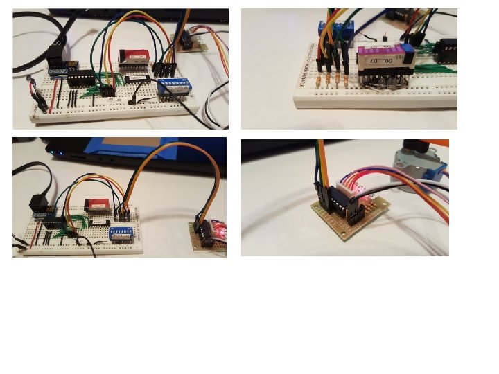
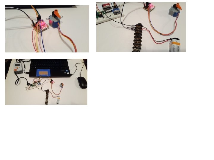

NXT Brick ULN 2003 Motor Board 28 BYJ-48 Stepper PCF 8574 Board Common Ground Screw Terminal Bar Motor Power Supply 9 V Battery

3. 3 KOhm each 9 1 2 3 4 IN 1 IN 2 IN 3 IN 4 COM OUT 1 OUT 2 OUT 3 OUT 4 16 15 14 13 PINK ORANGE YELLOW BLUE RED 8 GND ULN 2003 Motor Voltage (5 -12 V) 28 BYJ-48 Stepper

NXT Cable NXT Adapter Board PCF 8574 Chip Green Wires: D 0 to D 7

Four 3. 3 KOhm pull-up Resistors ULN 2003 Board IN 1 -IN 4 PCF 8574 D 0 to D 3

28 BYJ-48 Stepper From PCF 8574: D 3 D 0 28 BYJ-48 Stepper ULN 2003 Board 1 IN 2 IN 3 IN D 2 From PCF 8574 4 IN D 1 ULN 2003 Board Stepper Cables (5 wires) Stepper Header Motor Voltage Header Common Ground + 9 V Battery - Screw terminal bar ULN 2003 Board Motor Voltage Header


- Slides: 21