Block diagram of a colour TV receiver l

Block diagram of a colour TV receiver

l The receiving antenna intercepts radiated RF signals and the tuner selects desired channel’s frequency band converts it to the common IF band of frequencies. l The receiver employs two or three stages of intermediate frequency (IF) amplifiers. The output from the last IF stage is demodulated to recover the video signal. .

l This signal that carries picture information is amplified and coupled to the picture tube which converts the electrical signal back into picture elements of the same degree of black, white and color.

Sound Reception l The path of sound signal is common with the picture signal from antenna to video detector section of the receiver. Here the two signals are separated and fed to their respective channels. l The frequency modulated audio signal is demodulated after at least one stage of amplification. l The audio output from the FM detector is given due amplification before feeding it to the loudspeaker

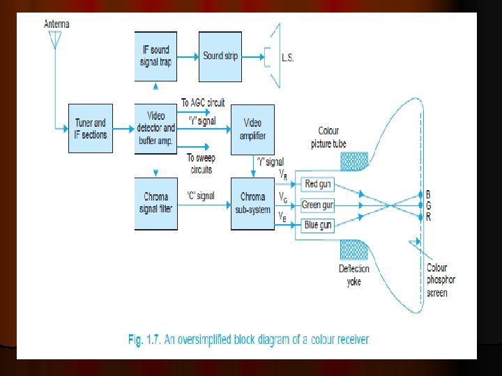
Colour Receiver l. A colour receiver is similar to the black and white receiver as shown in Fig. l The main difference between the two is the need of a colour or chroma Subsystem. It accepts only the colour signal and processes it to recover (B-Y) and (R-Y) signals. l These are combined with the Y signal to obtain VR, VG and VB signals as developed by the camera at the transmitting end.

l VG becomes available as it is contained in the Y signal. l The three colour signals are fed after sufficient amplification to the colour picture tube to produce a colour picture on its screen.

Picture tube l the colour picture tube has three guns corresponding to the three pick-up l tubes in the colour camera. The screen of this tube has red, green and blue phosphors arranged in alternate stripes. l Each gun produces an electron beam to illuminate corresponding colour phosphor separately on the fluorescent screen.

l The eye then integrates the red, green and blue colour informations and their luminance to perceive actual colour and brightness of the picture being televised. l The sound signal is decoded in the same way as in a monochrome receiver.

RECEIVER CONTROLS l Most black and white receivers have on their front panel l (i) channel selector, (ii) fine tuning, l (iii) brightness, (iv) contrast, l (v) horizontal hold and l (vi) volume controls besides an ON-OFF switch. l l Some receivers also provide a tone control.

l The channel selector switch is used for selecting the desired channel. l The fine tuning control is provided for obtaining best picture details in the selected channel. l The hold control is used to get a steady picture in case it rolls up or down. l The brightness control varies beam intensity of the picture tube and is set for optimum average brightness of the picture

l The contrast control is actually gain control of the video amplifier. l The volume and tone controls form part of the audio amplifier in sound section, and are used for setting volume and tonal quality of the sound output from the loudspeaker. l In colour receivers there is an additional control called ‘colour’ or ‘saturation’ control. It is used to vary intensity or amount of colours in the reproduced picture
- Slides: 12