Bipolar Drive Circuit The following figure shows one

Bipolar Drive Circuit • The following figure shows one phase of a bipolar drive circuit suitable for the permanent magnet stepper motor. • The transistors are switched in pairs according to the current polarity required for the phase winding. • Transistors Tl and T 2 are turned on simultaneously so that current can flow from left to right in the phase winding.

• If transistors T 3 and T 4 are turned on simultaneously, current will flow in the opposite direction. • The four diodes Df are connected in antiparallel with the switching transistors to provide the paths for the freewheeling currents. • when Tl and T 2 are switched on, current flows from dc supply to T l, phase winding (left to right), T 2, and back to dc supply.
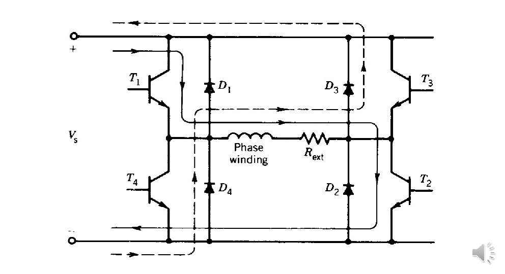

q When Tl and T 2 are switched off , current in the phase winding cannot decay instantaneously because of winding inductance. The current therefore flows through diodes D 3 and D 4 to the dc supply, as shown in figure by dashed lines. q Note that when current flows through and to the dc supply, some of the energy stored in the phase winding inductance at turnoff is returned to the supply. This improves the overall system efficiency.
, including variable reluctance types, are operated")
q. Most large stepper motors (>I k. W), including variable reluctance types, are operated from bipolar drive circuits. q. Bipolar drive circuits require more switching devices and are therefore more expensive than unipolar drive circuits. q. Note that the freewheeling currents in the bipolar drive circuit decay more rapidly than in the unipolar drive circuit, because the dc supply opposes them. Consequently no additional freewheeling resistance is necessary in the bipolar drive circuit

item Unipolar drive circuit Bipolar drive circuit Efficiency Small because the energy stored in the phase winding inductance at turnoff is lost as a heat in the free wheeling circuit. High because some of the energy stored in the phase winding inductance at turnoff is returned to the supply. Cost it requires less switching devices more expensive because it requires more switching devices Free wheeling resistance necessary is not needed because the free wheeling currents decay more rapidly because the dc supply opposes them. Application Small stepper motors large stepper motors (>1 k. W)

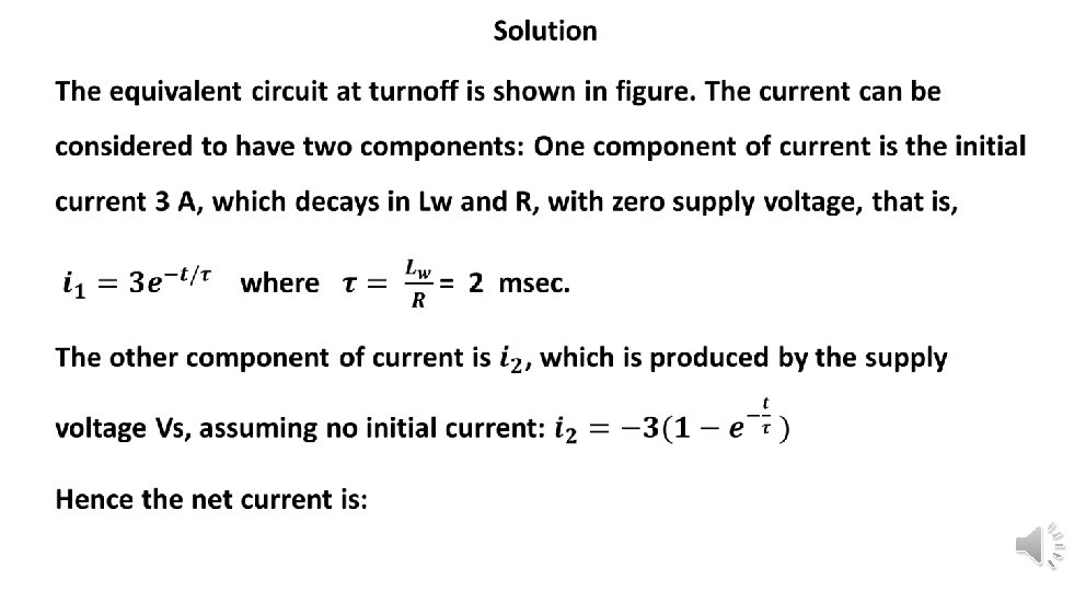
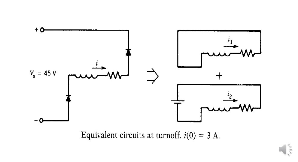
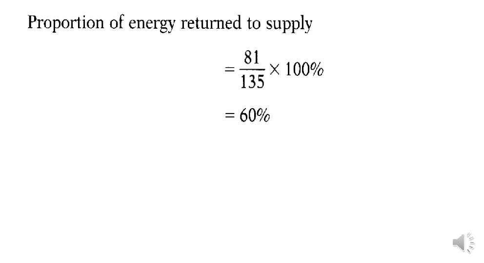
Example : A stepper motor driven by a bipolar drive circuit has the following parameters: Winding inductance (average) = 30 m. H Rated current = 3 A Total resistance in each phase R = 15 Ω DC supply = 45 V When transistors are turned off, determine the: (a) Time taken by the phase current to decay to zero. (b) Proportion of the stored inductive energy returned to the dc supply.

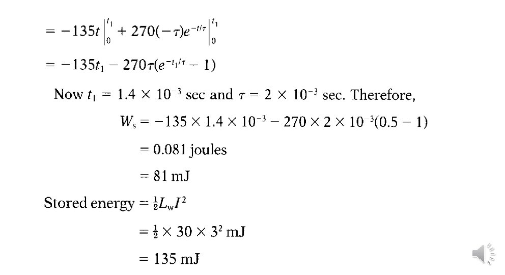
Energy returned to the supply, Ws:
- Slides: 12