BIOPOTENTIAL AMPLIFIERS ECG DR SAIDATUL ARDEENA BIOMEDICAL ELECTRONICS

BIOPOTENTIAL AMPLIFIERS : ECG DR. SAIDATUL ARDEENA. BIOMEDICAL ELECTRONICS ENGINEERING UNIVERSITI MALAYSIA PERLIS

• Amplifiers are an important part of modern instrumentation system for measuring bio-potentials. • Such measurements involve voltage that are often are at low levels, have high source impedances, or both. • Amplifiers are required to increase signal strength while maintaining high fidelity. • Amplifiers that have been designed specifically for this type of processing of bio potentials are known as ‘bio potential’ amplifiers.

Biopotential Amplifiers Basic function • To increase the amplitude of a weak electric signal of biological origin Biopotential Amplifier Amplified Biopotential 3

BASIC REQUIREMENTS • The essential function of a biopotential amplifier is to take a weak electric signal of biological origin and increase its amplitude. • So that, it can be further processed, recorded and displayed.

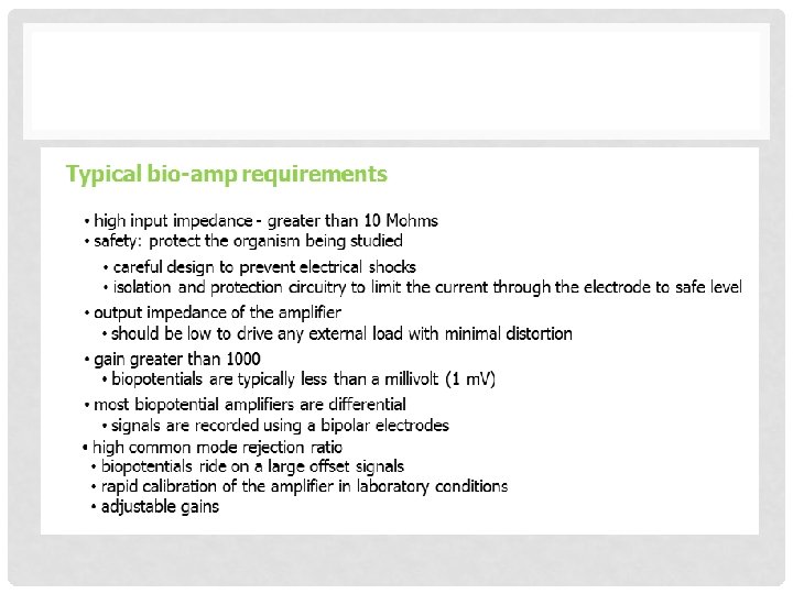
Biopotential Amplifiers The basic requirements that a biopotential amplifier has to satisfy are: q the physiological process to be monitored should not be influenced in any way by the amplifier the measured signal should not be distorted q the amplifier should provide the best possible separation of signal and interferences q the amplifier has to offer protection of the patient from any hazard of electrical shock q the amplifier itself has to be protected against damages that might result from high input voltages as they occur during the application of defibrillators or electrosurgical instrumentation 5

Voltage and Frequency Range for Biopotentials EOG = Electrooculogram EEG = Electro. Encephalogram ECG = Electro. Cardiogram ECG = Electro. Myogram 7

THE ECG • Beating heart generates an electric signal that can be used as a diagnostic tool for examining some of the functions f the heart. • This electric activity of the heart can be approximately represented as a vector quantity. • Electrocardiographers have developed a simple model to represent the electric activity of the heart. • In this model, the heart consists of an electric dipole located in the partially conducting medium of the thorax.

ELECTROCARDIOGRAPH AMPLIFIER

• Rough sketch of the dipole field of the heart when the R wave is maximal. The dipole consists of the points of equal positive and negative charge separated from one another and denoted by the dipole moment vector M.

Relationships between the two lead vectors a 1 and a 2 and the cardiac vector M. The component of M in the direction of a 1 is given by the dot product of these two vectors and denoted on the figure by va 1. Lead vector a 2 is perpendicular to the cardiac vector, so no voltage component is seen in this lead.

• Cardiologists use a standard notation such that the direction of the lead vector for lead I is 0°, that of lead II is 60°, and that of lead III is 120°. An example of a cardiac vector at 30° with its scalar components seen for each lead is shown.

The basic four limb electrodes: right arm left arm electrical polarity: neutral or ground negative positive (manipulated by the EKG machine) right leg left leg
 right arm left arm electrical polarity: neutral or ground negative")
Lead I (toward left) right arm left arm electrical polarity: neutral or ground negative positive right leg left leg
 right arm left arm electrical polarity: neutral or ground")
Lead II (toward left foot) right arm left arm electrical polarity: neutral or ground negative positive right leg left leg
 right arm left arm electrical polarity: neutral or ground")
Lead III (down & rightward) right arm left arm electrical polarity: neutral or ground negative positive right leg left leg
 right arm left arm electrical polarity:")
Leads I, II, & III together (“Einthoven’s triangle”) right arm left arm electrical polarity: neutral or ground negative positive right leg left leg

Plus “augmented” leads, e. g. , a. VR right arm left arm electrical polarity: neutral or ground negative positive right leg left leg

Frontal view of heart a. VR a. VL I Limb Leads III a. VF II

Cross sectional view of heart V 1 Chest leads V 2 V 3 V 4 V 5 V 6

Summary: the 12 standard leads are : Limb leads – I, from the right arm (-) toward the left arm (+) (taken together, these II, from the right arm toward the left leg three form the classic III, from the left arm toward the left leg "Einthoven's triangle") a. VR, augmented lead toward the right (arm) (note: a. VR is approx. a. VL, augmented lead toward the left (arm) opposite of I and should a. VF, augmented lead toward the foot essentially mirror the shape of I vertically) Chest leads – V 1 through V 6, starting over the right atrium with V 1, and placed in a semi-circle of positions leftwards, to the left side of the left ventricle

Positions of the electrodes: right arm left arm V 1 V 2 V 3 V 4 V 5 V 6 (plus the electrodes on the legs)

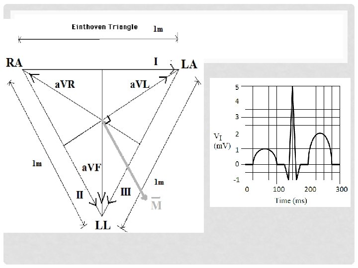
FRONTAL PLANE: EITHOVEN’S TRIANGLE • 4 electrodes : • • RA – right arm LA – left arm LL – left Leg RL – right leg (active grounding reference)
 I -")
• 6 leads in the frontal plane from three electrodes: (i) I - LA – RA (iv) VR – RA - WCT (ii) II - LL – RA (v) VL – LA - WCT (iii) III - LL –LA (vi) VF – LL – WCT Where WCT is the WILSON CENTRAL TERMINAL: virtual ground reference at the centre of the triangle WCT = 1/3 (RA+LA+LL)

AUGMENTED LEADS • Alternative constructions of the VR, L, and VF leads with magnitude closer to the I, III leads. Example: a. VR

6 leads and their complements , 360˚ in 30˚ increments on a polar plot.

FUNCTIONAL BLOCKS OF ECG

Problems in ECG Measurement • Frequency distortion • if filter specification does not match the frequency content of biopotential • then the result is high and low frequency distortion • Saturation or cutoff distortion • high electrode offset voltage or improperly calibrated amplifiers can drive the amplifier into saturation • then the peaks of QRS waveforms are cut off • Electric/magnetic field coupling • open lead wires (floating connections) pick up EMI (Electro. Magnetic. Interference) • long leads produce loop that picks up EMI (induces loop current) • Interference from power lines (common mode interference) • can couple onto ECG signal 60 Hz supply noise Coupled to ECG 28

INTERFERENCE REDUCTION TECHNIQUES

Differential Amplifier • One-amp differential amplifier • gain determination • Rule 1: virtual short at op-amp inputs • Rule 2: no current into op-amp Vin + gain of differential amplifier • characteristics • no common mode gain, Gc = 1 • input resistance of the diff. amp is lower than ideal op-amp • OK for low resistance sources (like Wheatstone bridge), but not good for many biomedical applications 30

Differential Amplifier • How do we fix low input resistance of 1 -op-amp diff amp? • Option 1: Add voltage follower to each input • Option 2: Add non inverting amp at each input • Provides additional gain 31

Instrumentation Amplifier • Better option: • connect Ri’s of input amps together • eliminate ground connection • This 3 -op-amp circuit is called an instrumentation amplifier • Input stage characteristics • low common-mode gain - rejects common mode voltages (noise) • high input impedance • input stage gain adjusted by R 1 32

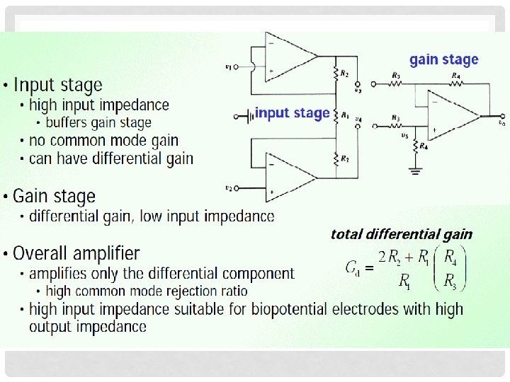
Instrumentation Amplifier • Input stage • high input impedance • buffers gain stage • no common mode gain • can have differential gain • Gain stage • differential gain, low input impedance • Overall amplifier • amplifies only the differential component • high common mode rejection ratio • high input impedance suitable for biopotential electrodes with high output impedance 33

ECG Amplifier instrumentation amplifier HPF non-inverting amp This ECG amplifier has a gain of 25 in the dc-coupled stages. The high-pass filter feeds a noninverting-amplifier stage that has a gain of 32. The total gain is 25 32 ¼ 800. When m. A 776 op amps were used, the circuit was found to have a CMRR of 86 d. B at 100 Hz and a noise level of 40 m. V peak to peak at the output. The frequency response was 0. 05 to 106 Hz for 3 d. B and was flat over 4 to 40 Hz. A single op-amp chip, the LM 324, that contains four individual op amps could also be used in this circuit reducing the total parts count. 34

EXERCISE • Consider the differential biopotential amplifier shown below. Assume all opamps are ideal.
 Find the differential gain Ad. b) Find the common mode gain Ac. What")
a) Find the differential gain Ad. b) Find the common mode gain Ac. What is the resulting CMRR? Is this value reasonable? c) Now assume that the opamps have input impedance Rin = 100 MΩ on each of the inputs to ground. What is now the common mode gain Ac and the resulting CMRR?
 Find the differential gain Ad.")
ANSWERS: a) Find the differential gain Ad.
 Find the common mode gain Ac. What is the resulting CMRR? Is this")
b) Find the common mode gain Ac. What is the resulting CMRR? Is this value reasonable?
 Now assume that the opamps have input impedance Rin = 100 MΩ on")
c) Now assume that the opamps have input impedance Rin = 100 MΩ on each of the inputs to ground. What is now the common mode gain Ac and the resulting CMRR?
: • According to Einthoven’s Triangle as shown, neatly sketch the voltage output")
PROBLEM (1): • According to Einthoven’s Triangle as shown, neatly sketch the voltage output of each of the remaining leads (II, III, a. VR, a. VL, a. VF) on separate graphs. • You may assume that the direction of the cardiac vector M remains parallel to the lead II axis throughout the ECG cycle. • On each of the graphs, label the axes and show the values of ECG amplitude at the P, R, and T waves.

SOLUTION:

ANSWER: VII

ANSWER: VIII

ANSWER:

ANSWER:

DRIVEN – RIGHT- LEG SYSTEM • A Driven Right Leg Circuit or “DRL” circuit is an electric circuit that is often added to biological signal amplifiers to reduce Commonmode interference. • Biological signal amplifiers such as ECG (Electrocardiogram) EEG (Electroencephalogram) or EMG circuits measure very small electrical signals emitted by the body, often as small as several micro-volts (millionths of a volt). • Unfortunately, the patient's body can also act as an antenna which picks up electromagnetic interference, especially 50/60 Hz noise from electrical power lines. • This interference can obscure the biological signals, making them very hard to measure. • Right Leg Driver circuitry is used to eliminate interference noise by actively canceling the interference.
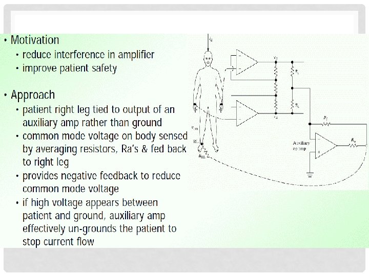
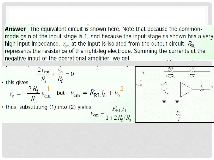
 Equivalent circuit of driven-rightleg system")
PROBLEM (2) Equivalent circuit of driven-rightleg system
- Slides: 52