Biometrics for Personal VerificationIdentification ChaurChin Chen Department of

Biometrics for Personal Verification/Identification Chaur-Chin Chen 陳朝欽 Department of Computer Science Institute of Information Systems & Applications National Tsing Hua University Hsinchu 30013, Taiwan E-mail: cchen@cs. nthu. edu. tw

What and Why is Biometrics? • What is Biometrics? Biometrics is the science and technology of interactively measuring and statistically analyzing biological data, in particular, taken from live people. • Why Biometrics? (1) The banking industry reports that false acceptance rate (FAR) at ATMs are as high as 30%, which results in financial fraud of US$2. 98 billion a year. (2) In U. S. , nearly half of all escapees from prisons leave through the front door, posing as someone else. (3) Roughly 4000 immigration inspectors at US ports-of-entry intercepted and denied admission to almost 800, 000 people. There is no estimate of those who may have gotton through illegally. (4) Personal verification/identification becomes a more serious job after the WTC attack on September 11, in the year 2001. u The evidence indicates that neither a PIN number nor a password is reliable.

Some Biometric Images

Gray Level and Color Images

Pixels in a Gray Level Image

Gray and Color Image Data • 0, 64, 144, 196, 225, 169, 100, 36 (R, G, B) for a color pixel Red – (255, 0) Green – ( 0, 255, 0) Blue – ( 0, 0, 255) Cyan – ( 0, 255) Magenta – (255, 0, 255) Yellow – (255, 0) Gray – (128, 128)

Outline • What is Biometrics? • Motivation by Evidence Iris Image Pattern Analysis Handwriting/Handprinting Verification Personal Signature Verification Hand Geometry Verification Voice (Speech) Pattern Recognition Face Image Recognition Fingerprint Image Verification/Identification Palmprint, Ear shape, Gesture, … • Fingerprint Classification and Verification • Face Image Recognition • Opportunities and Challenges

 holding nonimmigrant visas,")
US-VISIT • US-VISIT currently applies to all visitors (with limited exemptions) holding nonimmigrant visas, regardless of country of origin. • 2004 – US$ 330 million • 2005 – US$ 340 million • 2006 – US$ 340 million • 2007 – US$ 362 million


Implementation of An Automatic Fingerprint Identification System Peihao Huang, Chia-Yung Chang, Chaur-Chin Chen Department of Computer Science National Tsing Hua University Hsinchu 30013, Taiwan E-mail: cchen@cs. nthu. edu. tw Presented on May 19, 2007 in IEEE Int’l Conference on EIT

A Typical Fingerprint Image

Outline • A Flowchart of Fingerprint Identification ♪ Type Classification ♪ Minutiae Points Detection ♪ Minutiae Pattern Extraction ♪ Pattern Matching ♦ Databases: Rindex 28, Lindex 101 ♦ Experimental Results

Flowchart of An AFIS
 is image gray level at pixel (i,")
Image Enhancement • Support that A(i, j) is image gray level at pixel (i, j), μ and s 2 are the mean and variance of gray levels of input image, and α=150, γ=95, γ must satisfy γ>s. The enhanced image B( i , j ) is obtained by a contrast stretching given below • B( i , j ) α + γ * ([A ( i , j ) – μ]/s)

Result of Image Enhancement
 • First we apply a 5 by 5 median filter on")
Orientation Computation (1/4) • First we apply a 5 by 5 median filter on the image to avoid false gradient vectors generated by noise. • Then compute the gradient (Gx, Gy) at each pixel by a Sobel operator. z 1 z 2 z 3 z 4 z 5 z 6 z 7 z 8 z 9 mask Sobel Operation
![Orientation Computation (2/4) The relationship between [Gx, Gy]T and [ρ, θ]T](http://slidetodoc.com/presentation_image_h/21788cd500494009937443b46bd00b88/image-19.jpg "Orientation Computation (2/4) The relationship between [Gx, Gy]T and [ρ, θ]T")
Orientation Computation (2/4) The relationship between [Gx, Gy]T and [ρ, θ]T
 • Because of opposite gradient vectors might offset each other, we")
Orientation Computation (3/4) • Because of opposite gradient vectors might offset each other, we double the angles of the gradient vectors before averaging each block, and let the length of the gradient vectors be squared [5][6][10][11] • Let be represented by • The average gradient in each block R (w×w) is
 • The block gradient direction ψ is defined as where (a")
Orientation Computation (4/4) • The block gradient direction ψ is defined as where (a block direction) is defined as for

Results of Block Orientations Block orientated images
 • Because of noisy directions, we have to smooth the")
Singular Points Detection (1/2) • Because of noisy directions, we have to smooth the direction before computing the Poincaré index. • We regard the direction as a vector, double the angles and use a 3 by 3 averaging filter to smooth the direction. B 3 B 2 B 1 1 B 4 Bc B 0 1 2 1 B 5 B 6 B 7 1 1 1 • The average direction of the block is
 • We compute Poincaré index by summing up the difference")
Singular Points Detection (2/2) • We compute Poincaré index by summing up the difference in the direction surrounding the block P. For each block Pj, we compute the angle difference from 8 neighboring blocks along the counter-clockwise directions. P 1 → P 2 → P 3 → P 4 → P 5 → P 6 → P 7 → P 8 → P 1 P 8 P 7 P 2 P P 6 Core if the sum of difference is 180° P 3 P 4 P 5 Delta if the sum of difference is -180°

Example of An Ideal Core / | | � • | | |
 Singular points of Fingerprint Images")
Detected Singular Points (Blocks) Singular points of Fingerprint Images
 Right loop Whorl Others")
Criteria for Type Classification Type Arch Left (tented loop arch) Right loop Whorl Others (twins loop) # of cores 0 or 1 1 1 2 0 or >2 # of deltas 0 or 1 1(right) 1(left) (middle ) 0~2 0 or >2

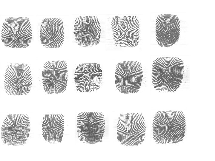
4+1 Fingerprint Type Classification Arch Left Loop Right Loop Whorl miscellaneous
 • Rindex 28, is obtained from PRIP Lab at NTHU. It")
Fingerprint Database (1) • Rindex 28, is obtained from PRIP Lab at NTHU. It contains 112 images of size 300 by 300 contributed by 28 different individuals. Each contributed 4 times with the same right index finger scanned by a Veridicom FPS 110 live scanner with the resolution 500 dpi
 • Lindex 101, is obtained from PRIP Lab at NTHU. It")
Fingerprint Database (2) • Lindex 101, is obtained from PRIP Lab at NTHU. It contains 404 images of size 300 by 300 contributed by 101 different individuals. Each contributed 4 times with the same left index finger scanned by a Veridicom FPS 110 live scanner with the resolution 500 dpi

Results of Classification • Experiment on Rindex 28: 4 x 28 right index fingerprint images collected from 28 students – No classification error • Experiment on Lindex 101: 4 x 101 left index fingerprint images are collected from 101 students – 17 classification errors ØDue to inappropriately pressing, too complex structure? , or poor quality.

Inappropriately Pressing Right Loop Arch ?

Inappropriately Pressing Whorl ? Left Loop ?

Too Complex Structure ? Left Loop or Whorl ? Left Loop or Arch ?

Fingerprint Images of Poor Quality ? X ? X

Outline • A Flowchart of Fingerprint Identification ♪ Type Classification ♪ Minutiae Points Detection ♪ Minutiae Pattern Extraction ♪ Pattern Matching ♦ Databases: Rindex 28, Lindex 101 ♦ Experimental Results

Flowchart of An AFIS
 • We have to distinguish valley from ridge of a fingerprint")
Image Binarization (1/2) • We have to distinguish valley from ridge of a fingerprint image before smoothing and thinning. So the gray value of pixels in the enhanced fingerprint image will be binarized to 0 or 255. • First we compute the gray value of P 25 and P 50 from the enhanced image, where Pk is the kth percentile of enhanced fingerprint image histogram. • Then we partition an enhanced fingerprint image into w by w blocks and compute the mean of each blocks. We define that Mj is the mean of the j-th block.
 • If the gray value of pixel Si is less than")
Image Binarization (2/2) • If the gray value of pixel Si is less than P 25, we assign 0 to Si. If the gray value of pixel Si greater than P 50, we assign 255 to Si. Otherwise, the pixel value is defined by the following rule:
 • After binarization, we find that there is still much noise on")
Post-Processing (Smoothing) • After binarization, we find that there is still much noise on ridge region. In order to make the result of thinning better, we have to smooth the fingerprint image first. A smooth stage uses neighboring pixels to remove noise. • First a 5 by 5 filter is used. The pixel pi is assigned by: pi = { 255 if Σ 5 x 5 Nw≧ 18 0 if Σ 5 x 5 Nb≧ 18 pi otherwise • Then a 3 by 3 filter is further proceed by: pi = { 255 if Σ 3 x 3 Nw≧ 5 0 if Σ 3 x 3 Nb≧ 5 pi otherwise
 Original image (b) Enhanced image (c) Binarization image (d) Smoothed image")
(a) Original image (b) Enhanced image (c) Binarization image (d) Smoothed image
![Thinning [9] • The purpose of thinning stage is to gain the skeleton structure](http://slidetodoc.com/presentation_image_h/21788cd500494009937443b46bd00b88/image-42.jpg "Thinning [9] • The purpose of thinning stage is to gain the skeleton structure")
Thinning [9] • The purpose of thinning stage is to gain the skeleton structure of a fingerprint image. • It reduces a binary image consisting of ridges and valleys into a ridge map of unit width. (d) Smoothed image (e) Thinned image

Minutiae Definition ♫ From a thinned image, we can classify each ridge pixel into the following categories according to its 8 -connected neighbors. ♫ A ridge pixel is called : l an isolated point if it does not contain any 8 -connected neighbor. l an ending if it contains exactly one 8 -connected neighbor. l an edgepoint if it has two 8 -connected neighbors. l a bifurcation if it has three 8 -connected neighbors. l a crossing if it has four 8 -connected neighbors.

Example of Minutiae Extraction
 endings that lie on the")
Spurious Minutiae Deletion • Spurious minutia pixels include: (a) endings that lie on the margins of the region of interest. (b) two “close” endings with the same ridge orientation. (c) an ending and a bifurcation that are connected and close enough. (d) two bifurcations that are too close.

Spurious Minutiae Elimination Due to broken ridges, fur effects, and ridge endings near the margins of an image, we have to remove the spurious minutiae as described below. (1) Two endings are too close (within 8 pixels) (2) An ending and a bifurcation are too close (< 8 pixels) (3) Two bifurcations are too close (< 8 pixels) (4) Minutiae are near the margins (< 8 pixels)
 • To avoid obtaining false singular points or minutiae,")
Region of Interest Detection (1/2) • To avoid obtaining false singular points or minutiae, we use mean and standard deviation in each block to determine if the block is “good” (not a marginal block) or not. where , and is the ratio of distance to the center of the fingerprint image. μ and σ are normalized to be in [0, 1]. • If v > 0. 8, the block is what we want.
 Enhanced image Region of interest")
Region of Interest Detection (2/2) Enhanced image Region of interest

Example of Minutiae Extraction

Example of Minutiae Extraction

Example of Minutiae Extraction

Minutiae Pattern Matching

Minutiae Pattern Matching

Minutiae Pattern Representation • Fingerprint Template Data The information format of fingerprint template data. Type #of cores 4 bits 2 bits Core* # of deltas Delta* # of minutiae Minutiae* 24 bits 26 bits 24 bits 7 bits The information format of singular points, core or delta. X Coordinate Y Coordinate Direction 10 bits 4 bits The information format of a minutia. Kind of Minutiae X Coordinate Y Coordinate Direction 2 bits 10 bits 4 bits

Fingerprint Matching Score The matching score of these two fingerprints is calculated by where M is the number of potential type-matching minutiae within a disk of a certain user-specified radius, R (12 pixels). r measures the distance between a pair of potentially matched minutiae points.
 • Rindex 28, is obtained from PRIP Lab at NTHU. It")
Fingerprint Database (1) • Rindex 28, is obtained from PRIP Lab at NTHU. It contains 112 images of size 300 by 300 contributed by 28 different individuals. Each contributed 4 times with the same right index finger scanned by a Veridicom FPS 110 live scanner with 500 dpi
 • Lindex 101, is obtained from PRIP Lab at NTHU. It")
Fingerprint Database (2) • Lindex 101, is obtained from PRIP Lab at NTHU. It contains 404 images of size 300 by 300 contributed by 101 different individuals. Each contributed 4 times with the same left index finger scanned by a Veridicom FPS 110 live scanner with 500 dpi
 • FVC 2000 Sensor Type Image Size Resolution DB")
FVC 2000 Fingerprint Database (3) • FVC 2000 Sensor Type Image Size Resolution DB 1 Low-cost Optical Sensor 300 x 300 500 dpi DB 2 Low-cost Capacitive Sensor 256 x 364 500 dpi DB 3 Optical Sensor 448 x 478 500 dpi DB 4 Synthetic Generator 240 x 320 about 500 dpi

Fingerprint Images from FVC 2000 Examples of fingerprint images from each database of FVC 2000

Experimental Results Rindex 28 Lindex 101 99. 11% 111/112 82. 67% 334/404 92. 50% 74/80 90. 00% 72/80 87. 50% 70/80 92. 50% 74/80 Enrolling time for each fingerprint image 0. 25 sec 0. 45 sec 0. 17 sec Matching time 0. 359 sec 3. 14 sec 0. 25 sec 0. 218 sec 0. 234 sec 0. 156 sec Recognition rate DB 1 DB 2 The experimental results of 6 databases DB 3 DB 4

Mismatched Fingerprint Images

Conclusion € We reveal three problems, which affect the results of an AFIS which merit further studies. (1) Noise produces the poor binarization results (2) Broken ridges result in the false orientation, which causes the misclassification of a fingerprint type (3) The shifted fingerprint image is difficult to match the minutiae pattern well, for example, the type misclassification due to the missing cores or deltas

Are They From the Same Person?

Challenges and Opportunities • A perfect biometric recognition system did not exist and may never exist • An application based on biometrics usually requests a perfect verification/identification • A collection of biometric data is usually time consuming and more or less intrudes personal privacy • The mechanism of achieving the trade-off between privacy and security merits studies.

SVD-Based Projection for Face Recognition Chou-Hao Hsu and Chaur-Chin Chen Department of Computer Science Institute of Information Systems & Applications National Tsing Hua University, Hsinchu, Taiwan 30013 E-mail: cchen@cs. nthu. edu. tw

Is this Lady in your database?
 be the ith face image of m by")
Training Face Images • Let Fi(j) be the ith face image of m by n from the jth subject, 1≦i≦Nj and 1≦j≦K, N 1+N 2+…. +Nk=N be the training face images. Define the mean image S as

Singular Value Decomposition S=UDVt • Do S=UDVt where U and V are orthogonal. • Select r, c with r≦m, c≦n such that d 11+d 22+…+dhh ≧ 85% of trace(D), where h=min{r, c} • Let Ur =[u 1, u 2, . . . , ur], Vc =[v 1, v 2, …, vc] • Where U is an m by m orthogonal matrix • V is an n by n orthogonal matrix

Convert a face image into features • For each training image Ak, we represent this Ak as xk =(Ur)t. AVc , an r by c feature image • For each test image T, we represent T by y=(Ur)t. TVc , an r by c feature image

Distance between training feature images and a test feature image • • Compute d(y, xk) by Fröbenius norm The smaller Fröbenius norm, the closer Rank the norms in an ascending order Determine the recognition rates from ranks 1, 2, 3, . . . , 8 and plot the curve

Part of 5*40 Training Face Images

Missed Face Images and Their Wrongly-Best Matched Images

A Comparison of Difference Projection Methods

Are They the Same Person?

Challenges and Opportunities • A perfect biometric recognition system did not exist and will never exists • An application based on biometrics usually requests a perfect verification/identification • A collection of biometric data is usually time consuming and more or less intrudes personal privacy • The mechanism of achieving the trade-off between privacy and security merits studies.
- Slides: 75