Biomedical Signal processing Chapter 4 Sampling of Continuous

Biomedical Signal processing Chapter 4 Sampling of Continuous Time Signals Zhongguo Liu Biomedical Engineering School of Control Science and Engineering, Shandong University 山� 省精品� 程《生物医学信号� 理(双� )》 http: //course. sdu. edu. cn/bdsp. html 2021/5/19 1 1 Zhongguo Liu_Biomedical Engineering_Shandong Univ.

Chapter 4: Sampling of Continuous Time Signals 4. 0 Introduction 4. 1 Periodic Sampling 4. 2 Frequency Domain Representation of Sampling 4. 3 Reconstruction of a Bandlimited Signal from its Samples 4. 4 Discrete Time Processing of Continuous Time signals 4. 5 Continuous time Processing of Discrete Time Signal 2

4. 0 Introduction Ø Continuous time signal processing can be implemented through a process of sampling, discrete time processing, and the subsequent reconstruction of a continuous time signal. T: sampling period f=1/T: sampling frequency 3

Unit impulse train 4. 1 Periodic Sampling 冲激串序列 Continuous time signal T: sampling period impulse train sampling t Sampling sequence n 4
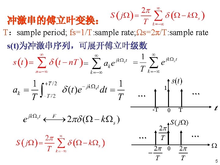

4. 2 Frequency Domain Representation of Sampling Representation of in terms of 7

Representation of in terms of , 数字角频率ω,rad 模拟角频率Ω, rad/s DTFT 采样角频率, rad/s 8
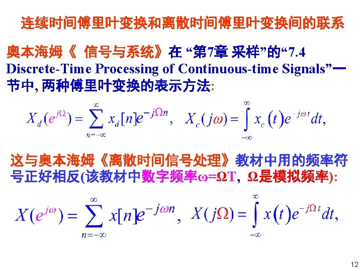

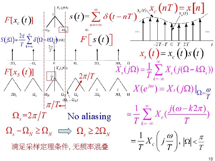
Representation of in terms of DTFT Continuous FT of Sampling DTFT without Aliasing 13
 in terms of Xc(jΩ) Aliasing 15")
Representation of X(ejω) in terms of Xc(jΩ) Aliasing 15

Nyquist Sampling Theorem • Let be a bandlimited signal with is. Then uniquely determined by its samples , if . • The frequency is commonly referred as the Nyquist frequency. • The frequency is called the Nyquist rate, which is the minimum sampling rate (frequency). without Aliasing 17

aliasing frequency 不满足采样定理条件 aliasing 19

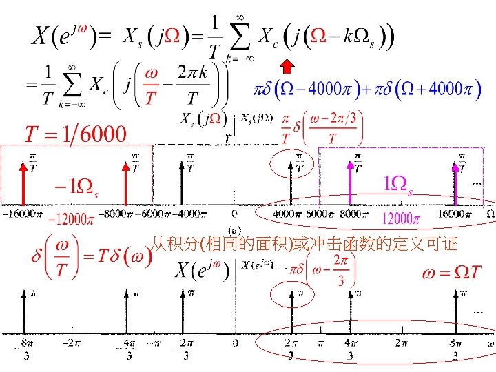
Example 4. 1: Sampling and Reconstruction of a sinusoidal signal Compare the continuous-time and discrete-time FTs for sampled signal Solution: 21

Example 4. 1: Sampling and Reconstruction of a sinusoidal signal continuous-time FT of discrete-time FT of 22

Ex. 4. 2: Aliasing in sampling an sinusoidal signal Compare the continuous-time and discrete-time FTs for sampled signal Solution: 24

Example 4. 2: Aliasing in the Reconstruction of an Undersampled sinusoidal signal continuous-time FT of discrete-time FT of 25

Ex. 4. 2: Aliasing in sampling an sinusoidal signal continuous-time FT of discrete-time FT of 低通滤波器 26

4. 3 Reconstruction of a Bandlimited Signal from its Samples 低通滤波器 Gain: T 28

4. 3 Reconstruction of a Bandlimited Signal from its Samples Gain: T CTFT DTFT 29

4. 3 Reconstruction of a Bandlimited Signal from its Samples CTFT DTFT 只要满足Qs ≥ 2 QN 重建原信号 30

4. 3 Reconstruction of a Bandlimited Signal from its Samples: 关于重建表达式的理解: 滤波 卷积 采样 重建过程 the ideal lowpass filter interpolates between the impulses of xs(t). 只要满足Q s ≥ 2 QN , 即可完全重建原信号。 重建 31 31

4. 4 Discrete Time Processing of Continuous Time signals 32

4. 4 Discrete Time Processing of Continuous Time signals 33

4. 4. 1 LTI DT Systems Is the system Linear Time. Invariant? 采样频率 即采样时无频率混叠. 36

Linear and Time Invariant • Linear and time-invariant behavior of the system of Fig. 4. 10 depends on two factors: • Firstly, the discrete-time system must be linear and time invariant. • Secondly, the input signal must be bandlimited, and the sampling rate must be high enough to satisfy Nyquist Sampling Theorem. (避免频率混叠 ) 37

等效的连续时间系统 必须是带限的. This is the effective frequency response of the overall LTI continuous time system. 38

Example 4. 3 bulid a Ideal Continuous Time Lowpass Filtering using a Discrete Time Filter Given LTI DT System -π π Solution: LTI CT System 39

Example 4. 3 Ideal Continuous Time Lowpass Filtering using a Discrete Time Filter Figure 4 12 interpretation of how this effective response is achieved. ? 40

Example 4. 3 Ideal Continuous Time Lowpass Filtering using a Discrete Time Filter Figure 4 12 interpretation of how this effective response is achieved. ? 等效连续低 通滤波器频 率响应 41

Example 4. 4: Discrete Time Implementation of an Ideal Continuous Time Bandlimited Differentiator If inputs are bandlimited, Solution: Differentiator: • Frequency response: • The inputs are restricted to be bandlimited. • For bandlimited signals, it is sufficient that: 高于π/T的频率响应也用不 到. has frequency • The corresponding DT system response: 42

Example 4. 4: Discrete Time Implementation of an Ideal Continuous Time Bandlimited Differentiator • effective frequency response : • frequency response for DT system : 43

Example 4. 4: Discrete Time Implementation of an Ideal Continuous Time Bandlimited Differentiator • frequency response for DT system : • The corresponding impulse response : • or equivalently, 44

4. 4. 2 Impulse Invariance Given: Design: 关系? impulse-invariant version of the 脉冲响应不变型 continuous time system 45
 is")
4. 4. 2 Impulse Invariance Ø Two constraints 脉冲响应不变法 1. 这是前面推出的结果要求 2. hc(t) is bandlimited 且与采样频率关 系? 截止频率 采样不产生频率混叠 脉冲响应不变型 The discrete-time system is called an impulse-invariant version of the continuous time system. If Let 46

Example 4. 5: A Discrete Time Lowpass Filter Obtained by Impulse Invariance • Suppose that we wish to obtain an ideal lowpass discrete time filter with cutoff fre quencyω c < π , • by sampling a continuous time ideal lowpass filter with cutoff frequency /T Nyquist Ω frequency Ωc <π采样频率/2 c = ωc /T< 满足采样定理条件 defined by : find Solution: • The impulse response of CT system : 47

Example 4. 5: A Discrete Time Lowpass Filter Obtained by Impulse Invariance • The impulse response of CT system : • so define the impulse response of DT system to be: check the frequency response • The DTFT of this sequence : Ωc = ωc /T< π /T 满足采样定理条件, 无频率混叠 48

Example 4. 6: Impulse Invariance Applied to Continuous Time Systems with Rational System Functions • Many CT systems have impulse responses of 频带 form: 无限 • Its Laplace transform: • apply impulse invariance concept to CT system, we obtain the h[n] of DT system: 不满足采样定理条件 • which has z transform system function: 49

Example 4. 6: Impulse Invariance Applied to CT Systems with Rational System Functions • CT system have impulse responses of form: L • Sampling: • z transform : • assuming Re(s 0) < 0, the frequency response: 单位圆在收敛域 存在FT 不满足采样定理条件, 存在频率混叠 但对高阶系统, 频率混叠可忽略, 所以脉冲响应不变法可用于设计滤 50 波器。

4. 5 Continuous time Processing of Discrete Time Signal Fig ure 4. 15 Øthe system of Fig ure 4. 15 is not typically used to implement discrete time systems, Øit provides a useful interpretation of certain discrete time systems that have no simple interpretation in the discrete domain. 52

4. 5 Continuous time Processing of Discrete Time Signal Sampling without aliasing 54

4. 5 Continuous time Processing of Discrete Time Signal 55

Example 4. 7: Non integer Delay • The frequency response of a discrete time system • When is integer, integer Δ • When (=0. 5) is not an integer, it has no formal meaning we cannot shift the sequence x[n] by. interpreted by system 如何理解? • (=0. 5) It can be 56

Example 4. 7: Non integer Delay Let • It represents a time delay of • and 对连续时间系统 T seconds. Therefore, 输出y[n]是将x[n]先变 换成xc(t), 将其延迟ΔT (0. 5 T)时刻之后再采样 得到的离散时间序列. 57

Ex. 4. 7: Non integer Delay 重建 用图形表示该过程 • For =1/2 58

Example 4. 7: Non integer Delay for LTI system, proof? DTFT • When = n 0 is integer, 59

Review u What is Nyquist rate? u What is Nyquist frequency? u The Nyquist rate is two times the bandwidth of max frequency a bandlimited signal. u The Nyquist frequency is one half the Nyquist rate. u (The Nyquist frequency is half the sampling minimum Sampling without aliasing frequency. ) 61

Review u How many factors does the linear and time invariant behavior of the system of Fig. 4. 11 depends on ? u First, the discrete time system must be linear and time invariant. u Second, the input signal must be bandlimited, and the sampling rate must be high enough to satisfy Nyquist Sampling Theorem. (避免频率混叠) 62

u Assume that we are given a desired continuous time system that we wish to implement in the form of the following figure, how to decide h[n] and H(ejw)? Review 63

Chapter 4 HW • 4. 5 2021/5/19 64 返 回 上一页 下一页 Zhongguo Liu_Biomedical Engineering_Shandong Univ.
- Slides: 54