
Binary Base2 Numbers Information may be reduced to
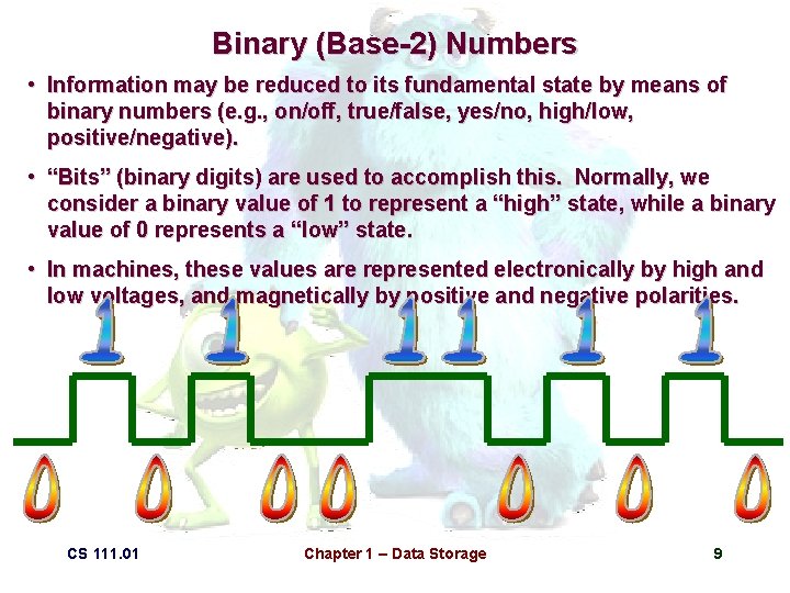
Binary (Base-2) Numbers • Information may be reduced to its fundamental state by means of binary numbers (e. g. , on/off, true/false, yes/no, high/low, positive/negative). • “Bits” (binary digits) are used to accomplish this. Normally, we consider a binary value of 1 to represent a “high” state, while a binary value of 0 represents a “low” state. • In machines, these values are represented electronically by high and low voltages, and magnetically by positive and negative polarities. CS 111. 01 Chapter 1 – Data Storage 9
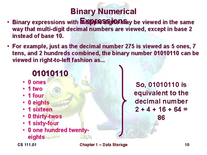
• Binary Numerical Binary expressions with Expressions multiple digits may be viewed in the same way that multi-digit decimal numbers are viewed, except in base 2 instead of base 10. • For example, just as the decimal number 275 is viewed as 5 ones, 7 tens, and 2 hundreds combined, the binary number 01010110 can be viewed in right-to-left fashion as. . . 01010110 0101011 010101 010 01 1010110 0110 10 • • 0 ones 1 two 1 four 0 eights 1 sixteen 0 thirty-twos 1 sixty-four 0 one hundred twentyeights CS 111. 01 Chapter 1 – Data Storage So, 01010110 is equivalent to the decimal number 2 + 4 + 16 + 64 = 86 10
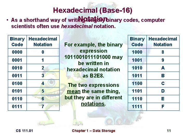
• Hexadecimal (Base-16) Notation As a shorthand way of writing lengthy binary codes, computer scientists often use hexadecimal notation. Binary Hexadecimal Code Notation 0000 0 0001 1 0010 2 0011 3 0100 4 0101 5 0110 6 0111 7 CS 111. 01 For example, the binary expression 1011001011101000 may be written in hexadecimal notation as B 2 E 8. The two expressions mean the same thing, but they are in different notations. Chapter 1 – Data Storage Binary Hexadecimal Code Notation 1000 8 1001 9 1010 A 1011 B 1100 C 1101 D 1110 E 1111 F 11
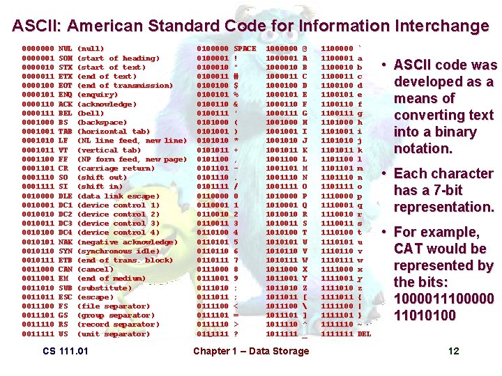
ASCII: American Standard Code for Information Interchange 00000001 0000010 0000011 0000100 0000101 0000110 0000111 0001000 0001001 0001010 0001011 0001100 0001101 0001110 0001111 0010000 0010001 0010010011 0010100 0010101 0010110 0010111 0011000 0011001 0011010 0011011 0011100 0011101 0011110 0011111 NUL SOH STX EOT ENQ ACK BEL BS TAB LF VT FF CR SO SI DLE DC 1 DC 2 DC 3 DC 4 NAK SYN ETB CAN EM SUB ESC FS GS RS US (null) (start of heading) (start of text) (end of transmission) (enquiry) (acknowledge) (bell) (backspace) (horizontal tab) (NL line feed, new line) (vertical tab) (NP form feed, new page) (carriage return) (shift out) (shift in) (data link escape) (device control 1) (device control 2) (device control 3) (device control 4) (negative acknowledge) (synchronous idle) (end of trans. block) (cancel) (end of medium) (substitute) (escape) (file separator) (group separator) (record separator) (unit separator) CS 111. 01 0100000 0100001 0100010 0100011 0100100101 0100110 0100111 0101000 0101001 010101011 0101100 0101101 0101110 0101111 0110000 0110001 0110010 0110011 0110100 0110101 0110110111 0111000 0111001 0111010 0111011 0111100 0111101 0111110 0111111 SPACE ! " # $ % & ' ( ) * + , . / 0 1 2 3 4 5 6 7 8 9 : ; < = > ? 1000000 1000001 1000010 1000011 1000100 1000101 1000110 1000111 1001000 1001001010 1001011 1001100 1001101 1001110 1001111 1010000 1010001 1010010 1010011 1010100 101010110 1010111 1011000 1011001 1011010 1011011100 1011101 1011110 1011111 @ A B C D E F G H I J K L M N O P Q R S T U V W X Y Z [ ] ^ _ Chapter 1 – Data Storage 1100000 1100001 1100010 1100011 1100100 1100101 1100110 1100111 1101000 1101001 1101010 1101011 1101100 1101101110 1101111 1110000 1110001 1110010 1110011 1110100 1110101 1110110 1110111 1111000 1111001 1111010 1111011 1111100 1111101 1111110 1111111 ` a b c d e f g h i j k l m n o p q r s t u v w x y z { | } ~ DEL • ASCII code was developed as a means of converting text into a binary notation. • Each character has a 7 -bit representation. • For example, CAT would be represented by the bits: 1000011100000 11010100 12

CCITT: Fax Conversion Code • Fax machines use binary code to represent the white and black spans on each ultra-thin scanline of alength page. white black length white black 0 1 2 3 4 5 6 7 8 9 10 11 12 13 14 15 16 17 18 19 20 21 22 23 24 25 26 27 28 29 30 31 00110101 000111 1000 1011 1100 1111 10011 10100 00111 01000 000011 110100 1101010 101011 0100111 0001100 0001000 0010111 0000011 0101000 0101011 0010011 0100100 0011000 00000011010 0000110111 010 11 10 011 0010 00011 000100 0000101 0000111 00000100 00000111 000011000 0000010111 0000011000 0000001000 0000100111 00001101000 00001101100 00000110111 00000101000 00000010111 00000011000 000011001011 00001100 00001101 000001101000 000001101001 CS 111. 01 32 33 34 35 36 37 38 39 40 41 42 43 44 45 46 47 48 49 50 51 52 53 54 55 56 57 58 59 60 61 62 63 00011011 00010010 00010011 00010100 00010101 00010110 00010111 00101000 00101001 00101010 00101011 00101100 00101101 00000100 000001010 00001011 01010010 01010011 01010100 0101 00100100101 01011000 01011001 01011010 01011011 01001010 01001011 00110010 00110100 000001101011 000011010010 000011010011 000011010100 000011010101 000011010110 000011010111 000001101100 0000011011010 000011011011 000001010100 000001010110 000001010111 000001100100 000001100101 000001010010 000001010011 000000100100 000000110111 000000111000 000000100111 000000101000 000001011001 000000101011 000000101100 000001011010 000001100111 Chapter 1 – Data Storage 64 128 192 256 320 384 448 512 576 640 704 768 832 896 960 1024 1088 1152 1216 1280 1344 1408 1472 1536 1600 1664 1728 1792 1856 1920 1984 2048 2112 2176 2240 2304 2368 2432 2496 2560 11011 10010 010111 0110111 00110110 00110111 01100100 01100101 01101000 01100111 01100 011010010 011010011 011010100 011010101 01101011010111 011011000 011011001 011011010 011011011 010011000 010011010 011000 010011011 00000001000 00000001101 000000010010 000000010011 000000010100 000000010101 000000010110 000000010111 000000011100 000000011101 000000011110 000000011111 000000111 000011001000 000011001001 000001011011 000000110100 000000110101 0000001101100 0000001101101 0000001001010 0000001001011 0000001001100 0000001001101 0000001110010 0000001110011 0000001110100 0000001110101 0000001110110 000000111 0000001010010 0000001010011 0000001010100 0000001011010 0000001011011 0000001100100 0000001100101 00000001000 00000001101 000000010010 000000010011 000000010100 000000010101 000000010110 000000010111 000000011100 000000011101 000000011110 000000011111 13
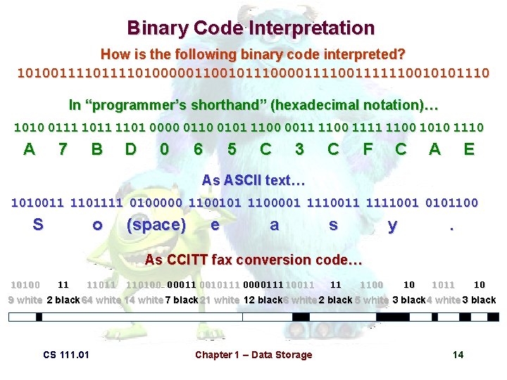
Binary Code Interpretation How is the following binary code interpreted? 101001111010000011001011100001111110010101110 In “programmer’s shorthand” (hexadecimal notation)… 1010 0111 1011 1101 0000 0110 0101 1100 0011 1100 1111 1100 1010 1110 A 7 B D 0 6 5 C 3 C F C A E As ASCII text… 1010011 1101111 0100000 1100101 1100001 1110011 1111001 0101100 S o (space) e a s y . As CCITT fax conversion code… 10100 11 110100 00011 0010111 0000111 10011 11 1100 10 1011 10 9 white 2 black 64 white 14 white 7 black 21 white 12 black 6 white 2 black 5 white 3 black 4 white 3 black CS 111. 01 Chapter 1 – Data Storage 14
Data Storage: Main Memory • Whenever a computer accesses information (e. g. , a program that’s being executed, data that’s being examined), that information is stored as electronic pulses within main memory. • Main memory is a system of electronic circuits known as random access memory (RAM), the idea being that the user can randomly access any part of memory (as long as the location of what’s being accessed is known). • The circuitry in main memory is usually dynamic RAM, meaning that the binary values must be continuously refreshed (thousands of times per second) or the charge will dissipate and the values will be lost. CS 111. 01 Chapter 1 – Data Storage 15
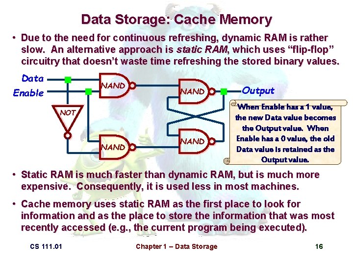
Data Storage: Cache Memory • Due to the need for continuous refreshing, dynamic RAM is rather slow. An alternative approach is static RAM, which uses “flip-flop” circuitry that doesn’t waste time refreshing the stored binary values. Data Enable NAND NOT NAND Output When Enable has a 1 value, the new Data value becomes the Output value. When Enable has a 0 value, the old Data value is retained as the Output value. • Static RAM is much faster than dynamic RAM, but is much more expensive. Consequently, it is used less in most machines. • Cache memory uses static RAM as the first place to look for information and as the place to store the information that was most recently accessed (e. g. , the current program being executed). CS 111. 01 Chapter 1 – Data Storage 16
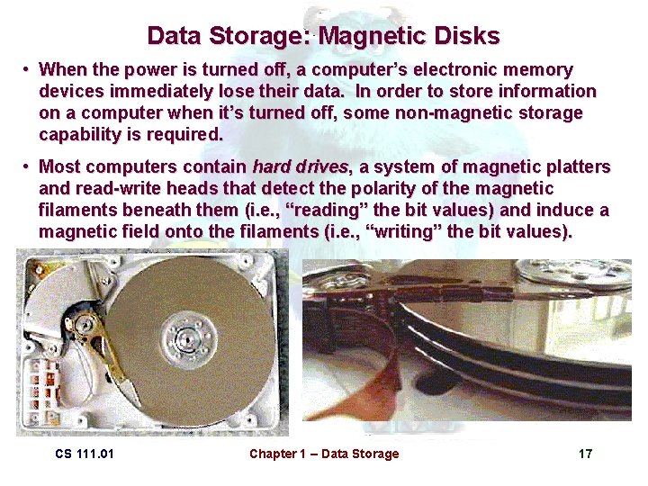
Data Storage: Magnetic Disks • When the power is turned off, a computer’s electronic memory devices immediately lose their data. In order to store information on a computer when it’s turned off, some non-magnetic storage capability is required. • Most computers contain hard drives, a system of magnetic platters and read-write heads that detect the polarity of the magnetic filaments beneath them (i. e. , “reading” the bit values) and induce a magnetic field onto the filaments (i. e. , “writing” the bit values). CS 111. 01 Chapter 1 – Data Storage 17
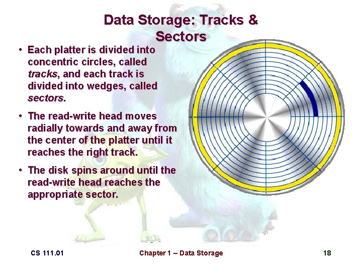
Data Storage: Tracks & Sectors • Each platter is divided into concentric circles, called tracks, and each track is divided into wedges, called sectors. • The read-write head moves radially towards and away from the center of the platter until it reaches the right track. • The disk spins around until the read-write head reaches the appropriate sector. CS 111. 01 Chapter 1 – Data Storage 18
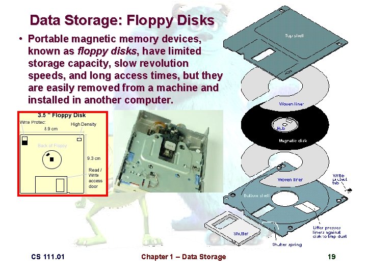
Data Storage: Floppy Disks • Portable magnetic memory devices, known as floppy disks, have limited storage capacity, slow revolution speeds, and long access times, but they are easily removed from a machine and installed in another computer. CS 111. 01 Chapter 1 – Data Storage 19
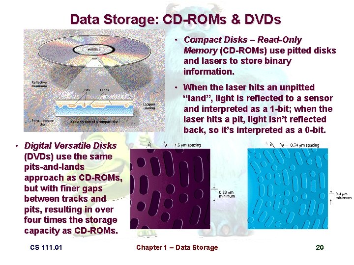
Data Storage: CD-ROMs & DVDs • Compact Disks – Read-Only Memory (CD-ROMs) use pitted disks and lasers to store binary information. • When the laser hits an unpitted “land”, light is reflected to a sensor and interpreted as a 1 -bit; when the laser hits a pit, light isn’t reflected back, so it’s interpreted as a 0 -bit. • Digital Versatile Disks (DVDs) use the same pits-and-lands approach as CD-ROMs, but with finer gaps between tracks and pits, resulting in over four times the storage capacity as CD-ROMs. CS 111. 01 Chapter 1 – Data Storage 20
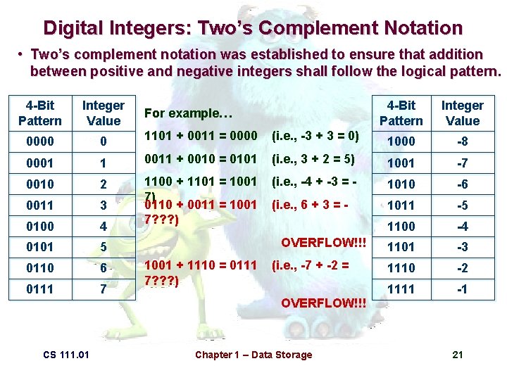
Digital Integers: Two’s Complement Notation • Two’s complement notation was established to ensure that addition between positive and negative integers shall follow the logical pattern. 4 -Bit Pattern Integer Value 0000 0 1101 + 0011 = 0000 0001 1 0010 2 0011 3 0100 4 0101 5 0110 6 0111 7 CS 111. 01 4 -Bit Pattern Integer Value (i. e. , -3 + 3 = 0) 1000 -8 0011 + 0010 = 0101 (i. e. , 3 + 2 = 5) 1001 -7 1100 + 1101 = 1001 7) 0110 + 0011 = 1001 7? ? ? ) (i. e. , -4 + -3 = - 1010 -6 (i. e. , 6 + 3 = - 1011 -5 1100 -4 1101 -3 1110 -2 1111 -1 For example… OVERFLOW!!! 1001 + 1110 = 0111 7? ? ? ) (i. e. , -7 + -2 = OVERFLOW!!! Chapter 1 – Data Storage 21
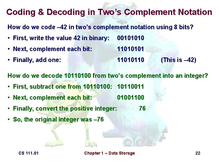
Coding & Decoding in Two’s Complement Notation How do we code – 42 in two’s complement notation using 8 bits? • First, write the value 42 in binary: 00101010 • Next, complement each bit: 11010101 • Finally, add one: 11010110 (This is – 42) How do we decode 10110100 from two’s complement into an integer? • First, subtract one from 10110100: 10110011 • Next, complement each bit: 01001100 • Finally, convert the positive integer: 76 • So, the original integer was – 76 CS 111. 01 Chapter 1 – Data Storage 22
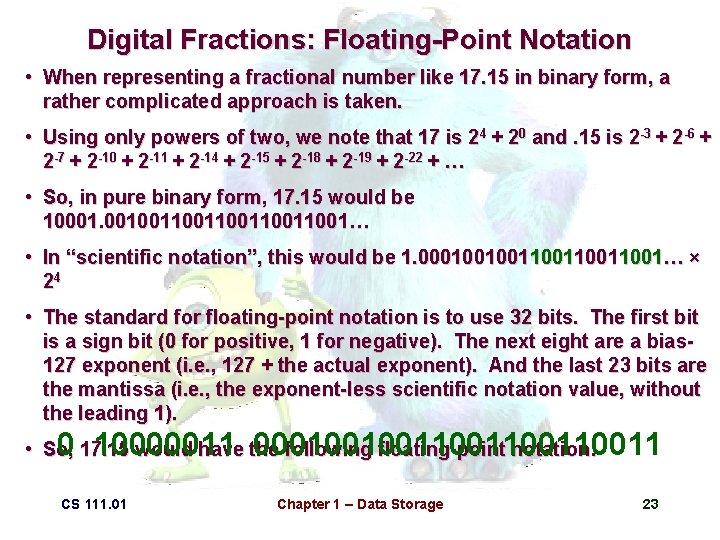
Digital Fractions: Floating-Point Notation • When representing a fractional number like 17. 15 in binary form, a rather complicated approach is taken. • Using only powers of two, we note that 17 is 24 + 20 and. 15 is 2 -3 + 2 -6 + 2 -7 + 2 -10 + 2 -11 + 2 -14 + 2 -15 + 2 -18 + 2 -19 + 2 -22 + … • So, in pure binary form, 17. 15 would be 10001. 00100110011001… • In “scientific notation”, this would be 1. 00010010011001… × 24 • The standard for floating-point notation is to use 32 bits. The first bit is a sign bit (0 for positive, 1 for negative). The next eight are a bias 127 exponent (i. e. , 127 + the actual exponent). And the last 23 bits are the mantissa (i. e. , the exponent-less scientific notation value, without the leading 1). 0 17. 15 10000011 000100100110011 • So, would have the following floating-point notation: CS 111. 01 Chapter 1 – Data Storage 23
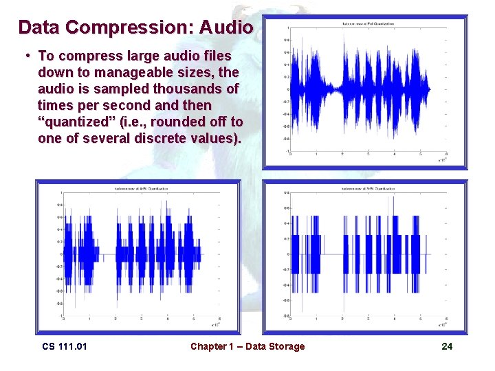
Data Compression: Audio • To compress large audio files down to manageable sizes, the audio is sampled thousands of times per second and then “quantized” (i. e. , rounded off to one of several discrete values). CS 111. 01 Chapter 1 – Data Storage 24
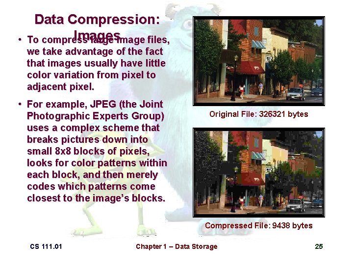
• Data Compression: Images To compress large image files, we take advantage of the fact that images usually have little color variation from pixel to adjacent pixel. • For example, JPEG (the Joint Photographic Experts Group) uses a complex scheme that breaks pictures down into small 8 x 8 blocks of pixels, looks for color patterns within each block, and then merely codes which patterns come closest to the image’s blocks. Original File: 326321 bytes Compressed File: 9438 bytes CS 111. 01 Chapter 1 – Data Storage 25
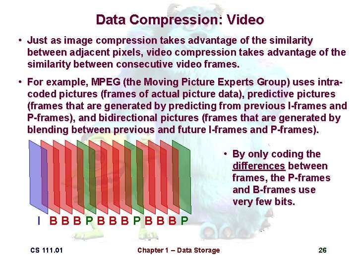
Data Compression: Video • Just as image compression takes advantage of the similarity between adjacent pixels, video compression takes advantage of the similarity between consecutive video frames. • For example, MPEG (the Moving Picture Experts Group) uses intracoded pictures (frames of actual picture data), predictive pictures (frames that are generated by predicting from previous I-frames and P-frames), and bidirectional pictures (frames that are generated by blending between previous and future I-frames and P-frames). • By only coding the differences between frames, the P-frames and B-frames use very few bits. I BBBPBBBP CS 111. 01 Chapter 1 – Data Storage 26
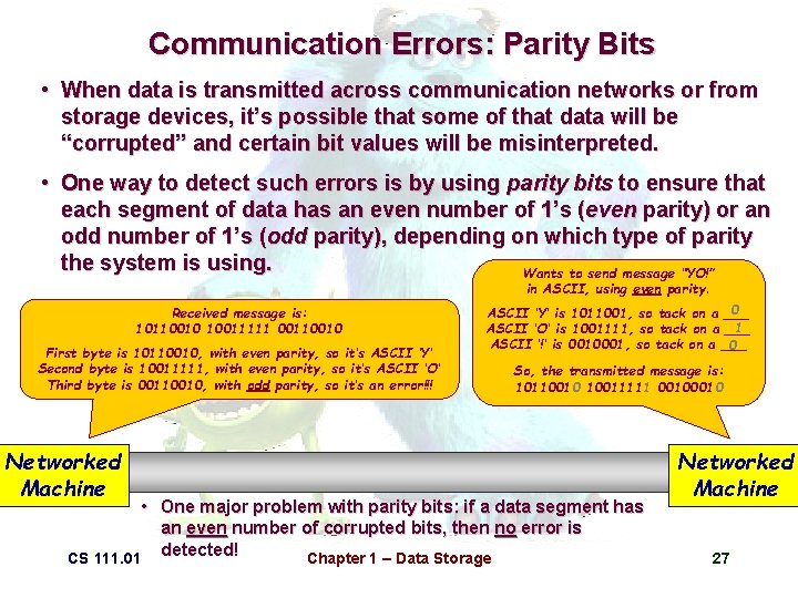
Communication Errors: Parity Bits • When data is transmitted across communication networks or from storage devices, it’s possible that some of that data will be “corrupted” and certain bit values will be misinterpreted. • One way to detect such errors is by using parity bits to ensure that each segment of data has an even number of 1’s (even parity) or an odd number of 1’s (odd parity), depending on which type of parity the system is using. Wants to send message “YO!” in ASCII, using even parity. Received message is: 10110010 10011111 00110010 First byte is 10110010, with even parity, so it’s ASCII ‘Y’ Second byte is 10011111, with even parity, so it’s ASCII ‘O’ Third byte is 00110010, with odd parity, so it’s an error!!! Networked 100010 Machine 0 ASCII ‘Y’ is 1011001, so tack on a ___ 1 ASCII ‘O’ is 1001111, so tack on a ___ ASCII ‘!’ is 0010001, so tack on a ___ 0 So, the transmitted message is: 10110010 10011111 0010 • One major problem with parity bits: if a data segment has an even number of corrupted bits, then no error is detected! CS 111. 01 Chapter 1 – Data Storage Networked Machine 27
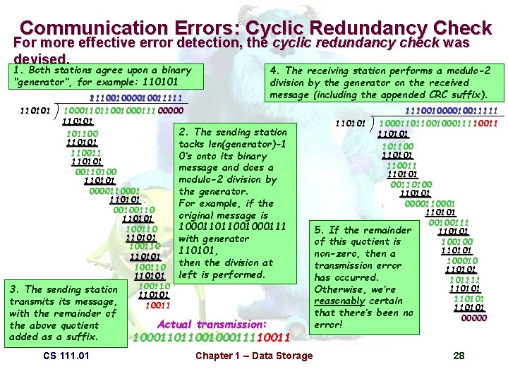
Communication Errors: Cyclic Redundancy Check For more effective error detection, the cyclic redundancy check was devised. 1. Both stations agree upon a binary “generator”, for example: 110101 4. The receiving station performs a modulo-2 division by the generator on the received message (including the appended CRC suffix). 1 11 11100100001001 111001000010011111 110101 100011011001000111 00000 110101 2. The sending station 101100 110101 tacks len(generator)-1 110011 0’s onto its binary 110101 message and does a 00110100 modulo-2 division by 110101 0000110001 the generator. 110101 For example, if the 00100110 original message is 110101 100011011001000111 100110 110101 with generator 100110 110101, 110101 then the division at 100110 left is performed. 110101 100110 3. The sending station 110101 transmits message, 10011 with the remainder of the above quotient added as a suffix. CS 111. 01 Actual transmission: 10001101100100011110011 Chapter 1 – Data Storage 1 11 11100100001001 111001000010011111 110101 100011011001000111 10011 110101 101100 110101 110011 110101 00110100 110101 0000110001 110101 00100111 5. If the remainder 110101 100100 of this quotient is 110101 non-zero, then a 100010 transmission error 110101 has occurred. 101111 110101 Otherwise, we’re 110101 reasonably certain 110101 that there’s been no 00000 error! 28
- Slides: 20