Bilinear Transformation When the impulse invariance method is

Bilinear Transformation

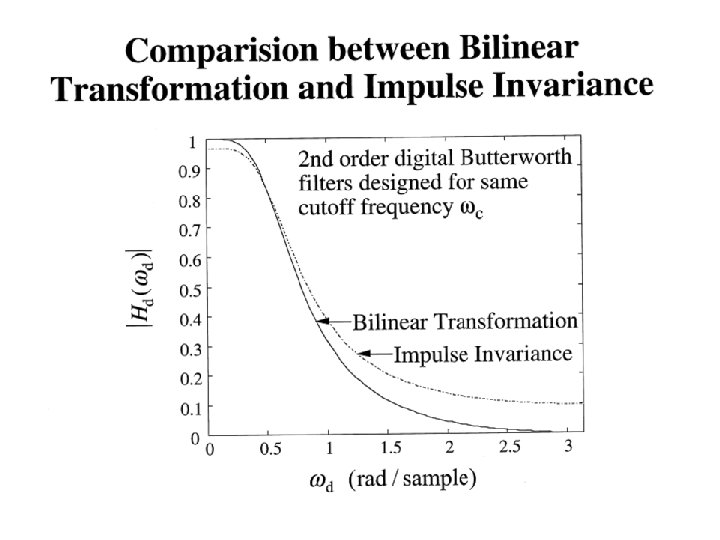
Ø When the impulse invariance method is used aliasing is encountered. Ø To reduce the distortion caused by aliasing one can tighten the specifications on the digital filter. Ø Aliasing occurs because points in the axis separated by 2 /T are mapped into the same digital frequency . Ø In the bilinear transformation method, there is a one-to-one correspondence between and . Therefore while transforming the analog filter to a digital filter aliasing is not encountered. Ø Since is limited to [- , ] range but varies from - to , it becomes clear that must be compressed when it is mapped to . In other words bilinear transformation is a non-linear transformation.
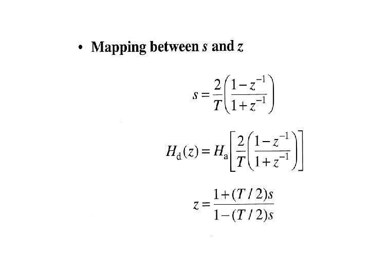
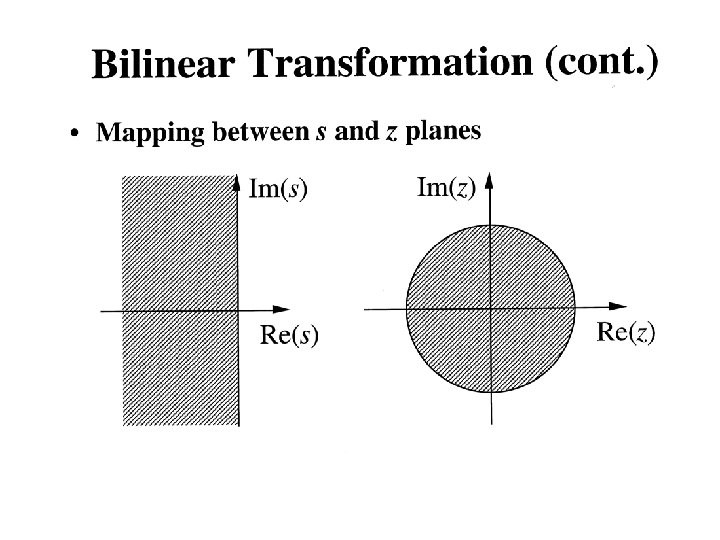

Figure below represents the relationship between and . Clearly compression occurs in the mapping process.

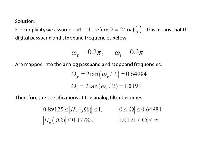
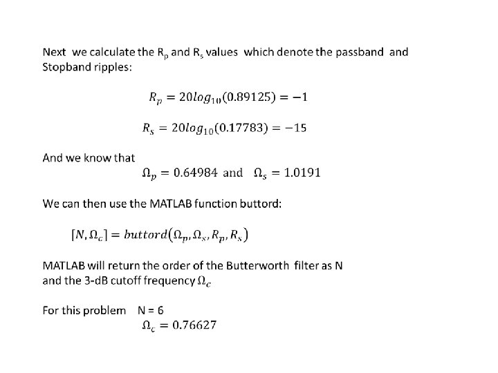
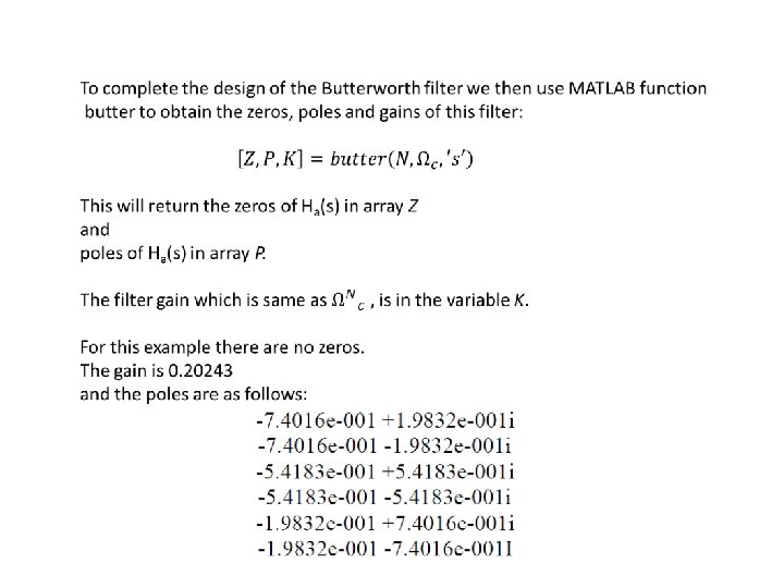
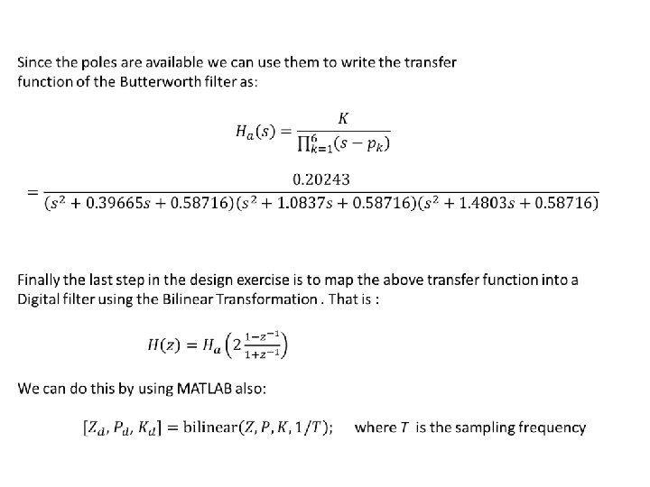
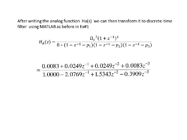
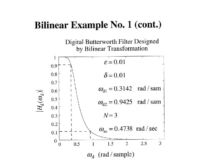
Example: Design a digital lowpass filter with the following specifications using the bilinear transformation method and a Butterworth prototype filter.

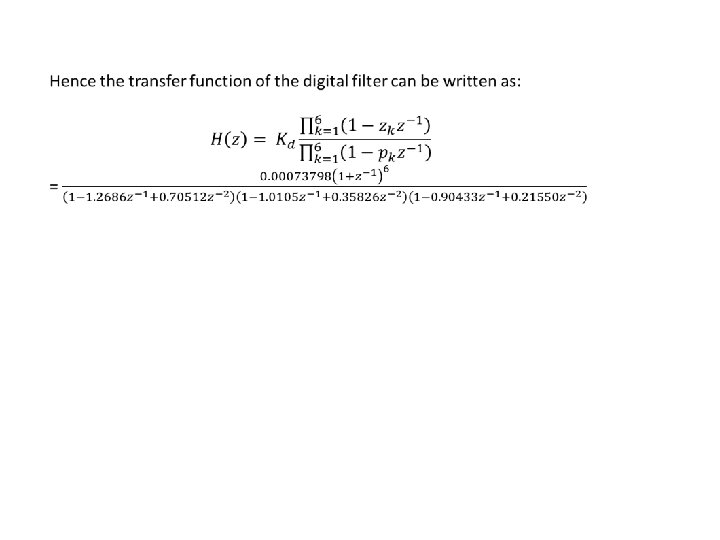
For this example : Kd = 0. 00073798 Zd = [ -1 -1 -1 ] and Pd = [ ]

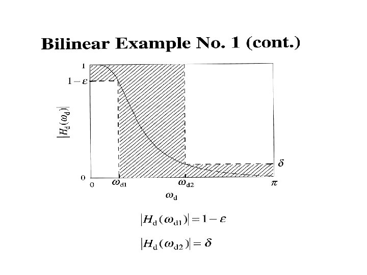
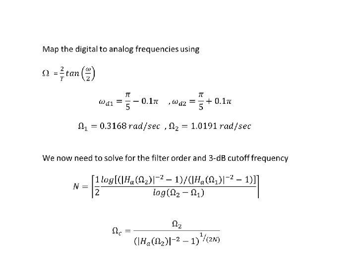
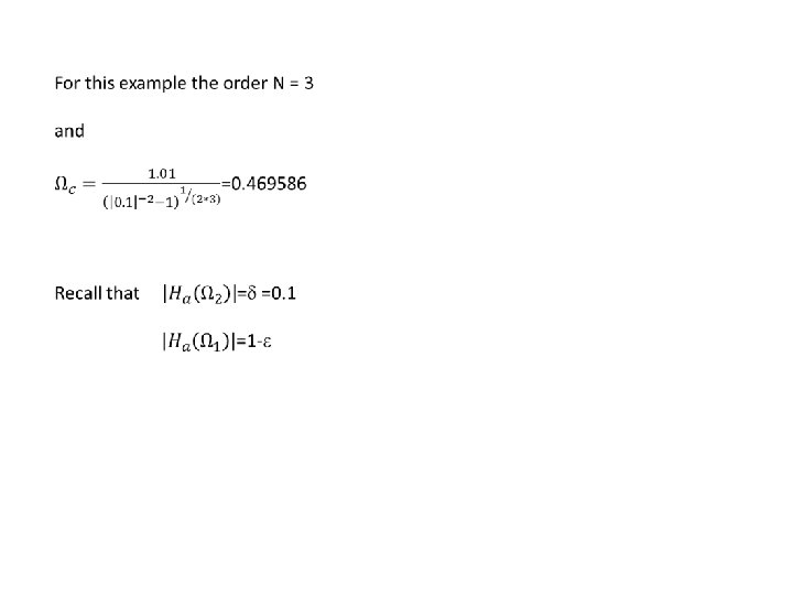
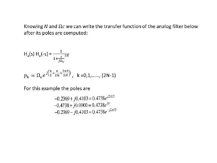
Example #2: Design a lowpass filter with § Cuttoff frequency c = /5 rad/sample § Transition bandwidth of = 0. 2 radians/sample = 0. 1 cycles/sample § With a ripple of = 0. 1 Use a Butterworth analog filter Set T = 1.
- Slides: 21