BGV Project Future Distance of closest approach DOCA

BGV Project Future
 vs track angle on the transverse plane (ɸ) Measured")
Distance of closest approach (DOCA) vs track angle on the transverse plane (ɸ) Measured beam spot position x = 0. 3 mm y = -0. 8 mm DOCA correlation (pairs of tracks from the same event)

L 0 Counters Veto Counters L 0 Confirm • New trigger electronics • CF Discriminators • Delay and coincidence logic (~10 ns coincidence window) • Additional scintillators (L 0 confirm)

NB: A well tuned trigger system may on its own measure relative • Bunch populations • Ghost bunch charge

For reconstructing the z profile of a beam bunch : need ~60 ps resolution MM: small amplification gap (50 -150 μm) - fast signals (~ 1 ns) - short recovery time (~50 ns) - high rate capabilities (> MHz/cm 2) - high gain (up to 105 or more) Time resolution already achieved: <50 ps Anode can be in the form of wide (~cm) strips to match the BGV geometry Could be placed possibly at the L 0 confirm support frame For more details see BE-BI seminar: Micro. Megas detector applications for beam diagnostics https: //indico. cern. ch/event/540799/

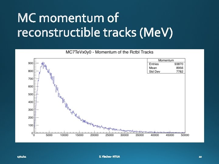
Analytical estimation MC reconstructible tracks DOCA error

Exit window ~ 3% X 0 One detector plane ~ 3% X 0 Table from R. Veness et al. , Proceedings of IPAC 2011 Detector material to be discussed at the detector upgrade part

• 100 μm pitch • 4 planes 30 x 30 cm 2 per multilayer (x, y, u, v) = 12. 5 Kchannels Silicon Strip sensors Micro. Megas detector Both F/E chips will be certified for operation in BGV-like radiation environment in 2027

To be used in high rate environments, a resistive strip plane has to be added (BGV ~ 1 KHz/cm 2)

Micromegas readout scheme Off-detector On-detector . . . VM VM M MM # of VMMs per FEB: MM: 8 RO C SC A Front end board GB TX L 1 DDC GB TX TT C FEL IX IX USA 1 Event 5 monito r RO D networ k Confi g calibratio n Trigger monitor DC S Bidirectional fiber One way fiber mini. SAS cables
- Slides: 21