
BERNOULLI AND ENERGY EQUATIONS MUHD HAFIZI BIN IDRIS
BERNOULLI AND ENERGY EQUATIONS MUHD HAFIZI BIN IDRIS TET 401 - 1 ST SEM 2011/2012

Objectives • Recognize various forms of mechanical energy, and work with energy conversion efficiencies. • Understand the use and limitations of the Bernoulli equation, and apply it to solve a variety of fluid flow problems. • Work with the energy equation expressed in terms of heads, and use it to determine turbine power output and pumping power requirements. TET 401 - 1 ST SEM 2011/2012

MECHANICAL ENERGY AND EFFICIENCY Mechanical energy • The form of energy that can be converted to mechanical work completely and directly by an ideal mechanical device such as an ideal turbine. Mechanical energy of a flowing fluid per unit mass: Flow energy + kinetic energy + potential energy Mechanical energy change: • The mechanical energy of a fluid does not change during flow if its pressure, density, velocity, and elevation remain constant. • In the absence of any irreversible losses, the mechanical energy change represents the mechanical work supplied to the fluid (if emech > 0) or extracted from the fluid (if emech < 0). TET 401 - 1 ST SEM 2011/2012
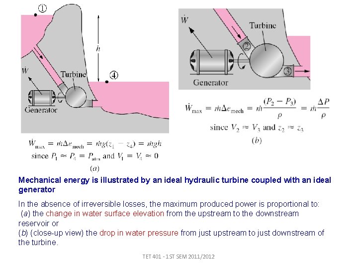
Mechanical energy is illustrated by an ideal hydraulic turbine coupled with an ideal generator In the absence of irreversible losses, the maximum produced power is proportional to: (a) the change in water surface elevation from the upstream to the downstream reservoir or (b) (close-up view) the drop in water pressure from just upstream to just downstream of the turbine. TET 401 - 1 ST SEM 2011/2012
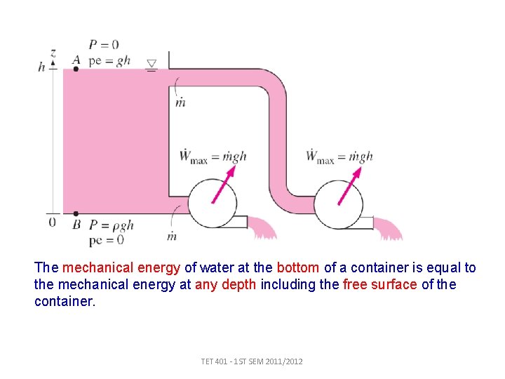
The mechanical energy of water at the bottom of a container is equal to the mechanical energy at any depth including the free surface of the container. TET 401 - 1 ST SEM 2011/2012
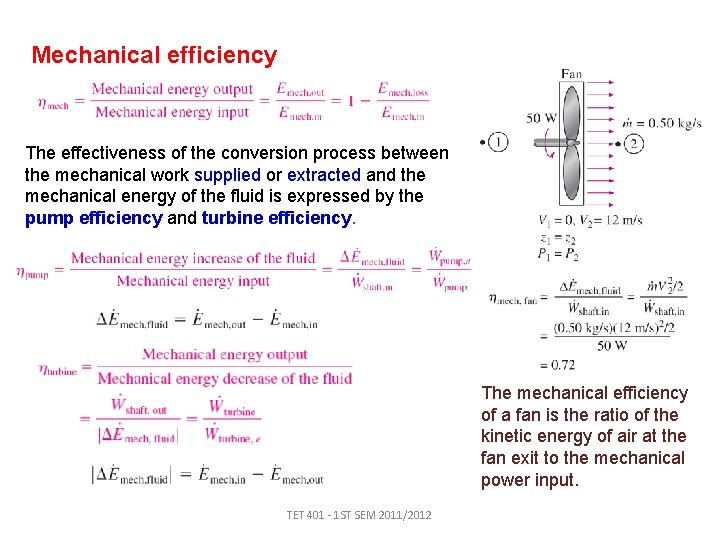
Mechanical efficiency The effectiveness of the conversion process between the mechanical work supplied or extracted and the mechanical energy of the fluid is expressed by the pump efficiency and turbine efficiency. The mechanical efficiency of a fan is the ratio of the kinetic energy of air at the fan exit to the mechanical power input. TET 401 - 1 ST SEM 2011/2012
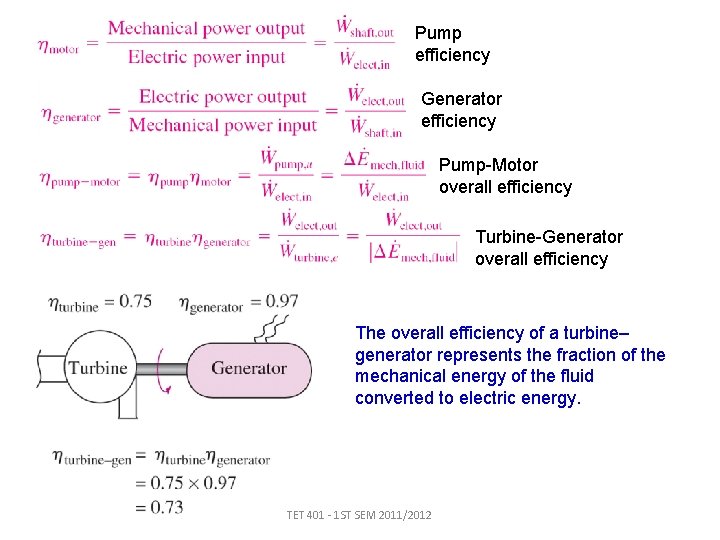
Pump efficiency Generator efficiency Pump-Motor overall efficiency Turbine-Generator overall efficiency The overall efficiency of a turbine– generator represents the fraction of the mechanical energy of the fluid converted to electric energy. TET 401 - 1 ST SEM 2011/2012
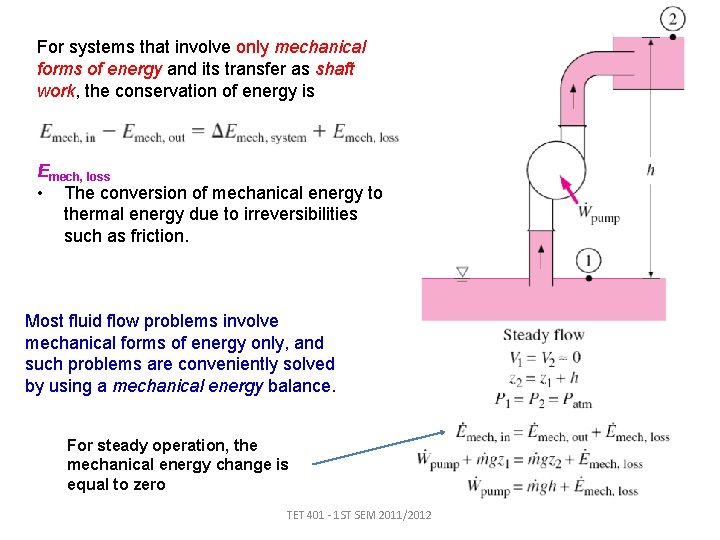
For systems that involve only mechanical forms of energy and its transfer as shaft work, the conservation of energy is Emech, loss • The conversion of mechanical energy to thermal energy due to irreversibilities such as friction. Most fluid flow problems involve mechanical forms of energy only, and such problems are conveniently solved by using a mechanical energy balance. For steady operation, the mechanical energy change is equal to zero TET 401 - 1 ST SEM 2011/2012
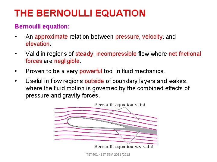
THE BERNOULLI EQUATION Bernoulli equation: • An approximate relation between pressure, velocity, and elevation. • Valid in regions of steady, incompressible flow where net frictional forces are negligible. • Proven to be a very powerful tool in fluid mechanics. • Useful in flow regions outside of boundary layers and wakes, where the fluid motion is governed by the combined effects of pressure and gravity forces. TET 401 - 1 ST SEM 2011/2012
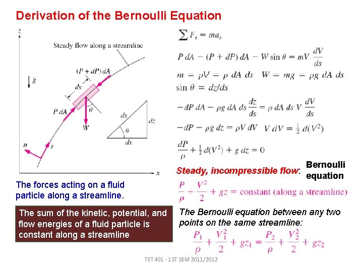
Derivation of the Bernoulli Equation Steady, incompressible flow: The forces acting on a fluid particle along a streamline. The sum of the kinetic, potential, and flow energies of a fluid particle is constant along a streamline Bernoulli equation The Bernoulli equation between any two points on the same streamline: TET 401 - 1 ST SEM 2011/2012
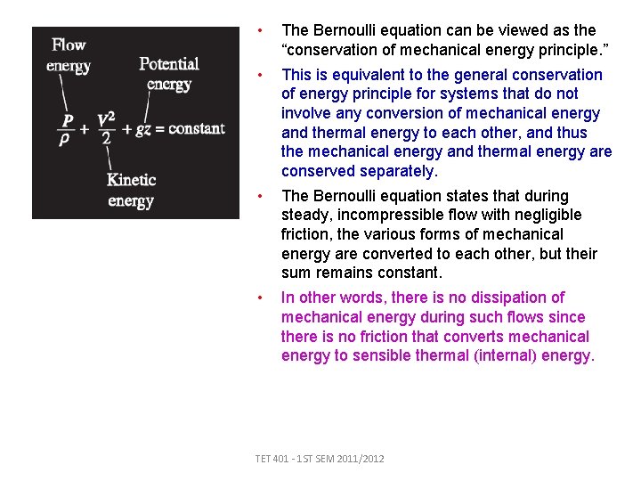
• The Bernoulli equation can be viewed as the “conservation of mechanical energy principle. ” • This is equivalent to the general conservation of energy principle for systems that do not involve any conversion of mechanical energy and thermal energy to each other, and thus the mechanical energy and thermal energy are conserved separately. • The Bernoulli equation states that during steady, incompressible flow with negligible friction, the various forms of mechanical energy are converted to each other, but their sum remains constant. • In other words, there is no dissipation of mechanical energy during such flows since there is no friction that converts mechanical energy to sensible thermal (internal) energy. TET 401 - 1 ST SEM 2011/2012
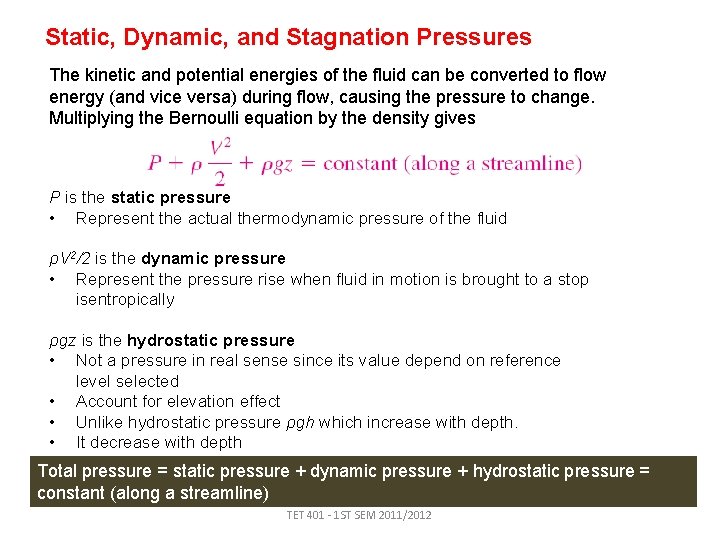
Static, Dynamic, and Stagnation Pressures The kinetic and potential energies of the fluid can be converted to flow energy (and vice versa) during flow, causing the pressure to change. Multiplying the Bernoulli equation by the density gives P is the static pressure • Represent the actual thermodynamic pressure of the fluid ρV 2/2 is the dynamic pressure • Represent the pressure rise when fluid in motion is brought to a stop isentropically ρgz is the hydrostatic pressure • Not a pressure in real sense since its value depend on reference level selected • Account for elevation effect • Unlike hydrostatic pressure ρgh which increase with depth. • It decrease with depth Total pressure = static pressure + dynamic pressure + hydrostatic pressure = constant (along a streamline) TET 401 - 1 ST SEM 2011/2012
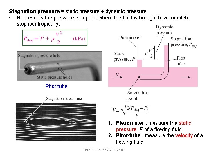
Stagnation pressure = static pressure + dynamic pressure • Represents the pressure at a point where the fluid is brought to a complete stop isentropically. Pitot tube 1. Piezometer : measure the static pressure, P of a flowing fluid. 2. Pitot-tube : measure the velocity of a flowing fluid TET 401 - 1 ST SEM 2011/2012
Limitations on the Use of the Bernoulli Equation 1. Steady flow 2. Frictionless flow 3. No shaft work • Not applicable in a flow section that involves a pump, turbine, fan, or any other machine or impeller since such devices destroy the streamlines and carry out energy interactions with the fluid particles. • When these devices exist, the energy equation should be used instead. 4. Incompressible flow • Density is taken constant in the derivation of the Bernoulli equation. 5. No heat transfer • The density of a gas is inversely proportional to temperature and thus the Bernoulli equation should not be used. 6. Flow along a streamline TET 401 - 1 ST SEM 2011/2012
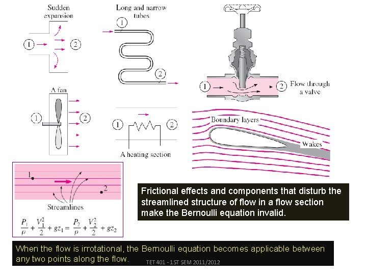
Frictional effects and components that disturb the streamlined structure of flow in a flow section make the Bernoulli equation invalid. When the flow is irrotational, the Bernoulli equation becomes applicable between any two points along the flow. TET 401 - 1 ST SEM 2011/2012
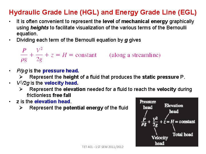
Hydraulic Grade Line (HGL) and Energy Grade Line (EGL) • • • It is often convenient to represent the level of mechanical energy graphically using heights to facilitate visualization of the various terms of the Bernoulli equation. Dividing each term of the Bernoulli equation by g gives P/ρg is the pressure head. Ø Represent the height of a fluid that produces the static pressure P. V 2/2 g is the velocity head. Ø Represent the elevation needed for a fluid to reach the velocity during frictionless free fall z is the elevation head. Ø Represent the potential energy of the fluid TET 401 - 1 ST SEM 2011/2012
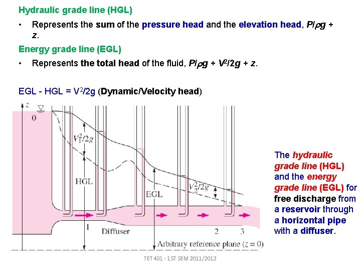
Hydraulic grade line (HGL) • Represents the sum of the pressure head and the elevation head, P/ g + z. Energy grade line (EGL) • Represents the total head of the fluid, P/ g + V 2/2 g + z. EGL - HGL = V 2/2 g (Dynamic/Velocity head) The hydraulic grade line (HGL) and the energy grade line (EGL) for free discharge from a reservoir through a horizontal pipe with a diffuser. TET 401 - 1 ST SEM 2011/2012
Notes on HGL and EGL • • For stationary bodies such as reservoirs or lakes, the EGL and HGL coincide with the free surface of the liquid. The EGL is always a distance V 2/2 g above the HGL. These two curves approach each other as the velocity decreases, and they diverge as the velocity increases. In an idealized Bernoulli-type flow, EGL is horizontal and its height remains constant. For open-channel flow, the HGL coincides with the free surface of the liquid, and the EGL is a distance V 2/2 g above the free surface. At a pipe exit, the pressure head is zero (atmospheric pressure) and thus the HGL coincides with the pipe outlet. The mechanical energy loss due to frictional effects (conversion to thermal energy) causes the EGL and HGL to slope downward in the direction of flow. The slope is a measure of the head loss in the pipe. A component, such as a valve, that generates significant frictional effects causes a sudden drop in both EGL and HGL at that location. A steep jump/drop occurs in EGL and HGL whenever mechanical energy is added or removed to or from the fluid (pump, turbine). The (gage) pressure of a fluid is zero at locations where the HGL intersects the fluid. The pressure in a flow section that lies above the HGL is negative, and the pressure in a section that lies below the HGL is positive. TET 401 - 1 ST SEM 2011/2012
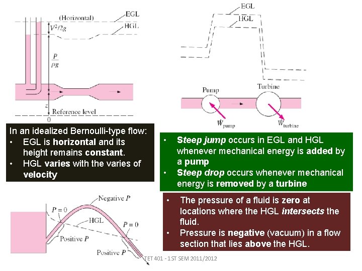
In an idealized Bernoulli-type flow: • EGL is horizontal and its height remains constant. • HGL varies with the varies of velocity • • Steep jump occurs in EGL and HGL whenever mechanical energy is added by a pump Steep drop occurs whenever mechanical energy is removed by a turbine The pressure of a fluid is zero at locations where the HGL intersects the fluid. Pressure is negative (vacuum) in a flow section that lies above the HGL. TET 401 - 1 ST SEM 2011/2012
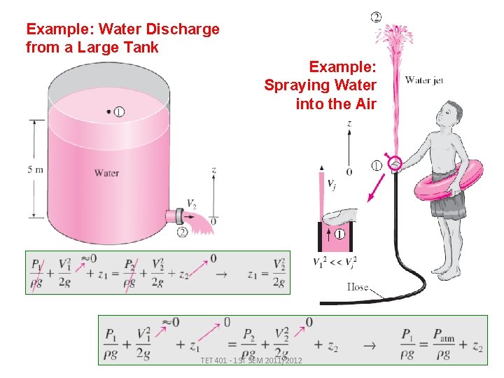
Example: Water Discharge from a Large Tank Example: Spraying Water into the Air TET 401 - 1 ST SEM 2011/2012
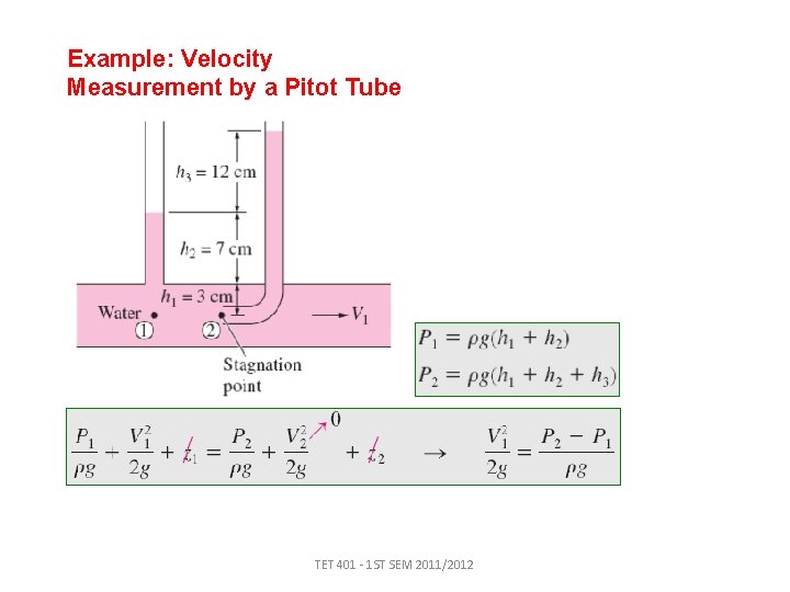
Example: Velocity Measurement by a Pitot Tube TET 401 - 1 ST SEM 2011/2012
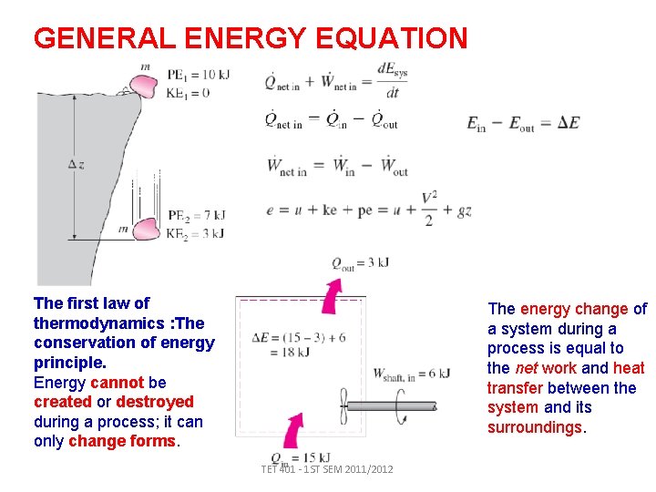
GENERAL ENERGY EQUATION The first law of thermodynamics : The conservation of energy principle. Energy cannot be created or destroyed during a process; it can only change forms. The energy change of a system during a process is equal to the net work and heat transfer between the system and its surroundings. TET 401 - 1 ST SEM 2011/2012
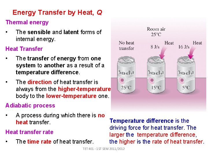
Energy Transfer by Heat, Q Thermal energy • The sensible and latent forms of internal energy. Heat Transfer • The transfer of energy from one system to another as a result of a temperature difference. • The direction of heat transfer is always from the higher-temperature body to the lower-temperature one. Adiabatic process • A process during which there is no Temperature difference is the heat transfer. driving force for heat transfer. The Heat transfer rate larger the temperature difference, the higher is the rate of heat transfer. • The time rate of heat transfer. TET 401 - 1 ST SEM 2011/2012
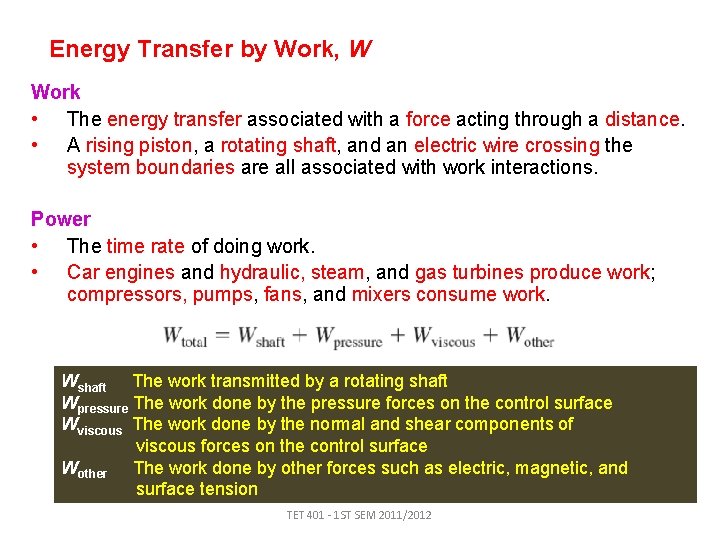
Energy Transfer by Work, W Work • The energy transfer associated with a force acting through a distance. • A rising piston, a rotating shaft, and an electric wire crossing the system boundaries are all associated with work interactions. Power • The time rate of doing work. • Car engines and hydraulic, steam, and gas turbines produce work; compressors, pumps, fans, and mixers consume work. Wshaft The work transmitted by a rotating shaft Wpressure The work done by the pressure forces on the control surface Wviscous The work done by the normal and shear components of viscous forces on the control surface Wother The work done by other forces such as electric, magnetic, and surface tension TET 401 - 1 ST SEM 2011/2012
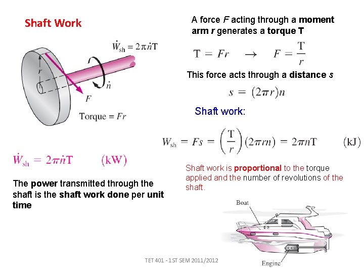
A force F acting through a moment arm r generates a torque T Shaft Work This force acts through a distance s Shaft work: The power transmitted through the shaft is the shaft work done per unit time Shaft work is proportional to the torque applied and the number of revolutions of the shaft. TET 401 - 1 ST SEM 2011/2012
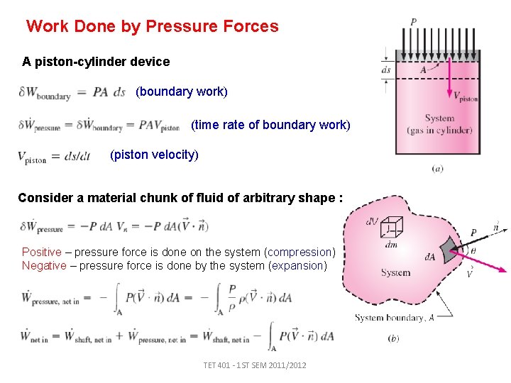
Work Done by Pressure Forces A piston-cylinder device (boundary work) (time rate of boundary work) (piston velocity) Consider a material chunk of fluid of arbitrary shape : Positive – pressure force is done on the system (compression) Negative – pressure force is done by the system (expansion) TET 401 - 1 ST SEM 2011/2012
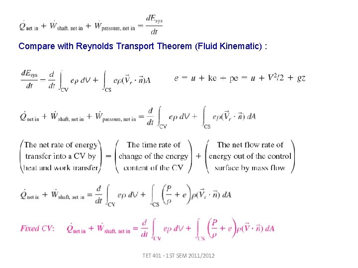
Compare with Reynolds Transport Theorem (Fluid Kinematic) : TET 401 - 1 ST SEM 2011/2012
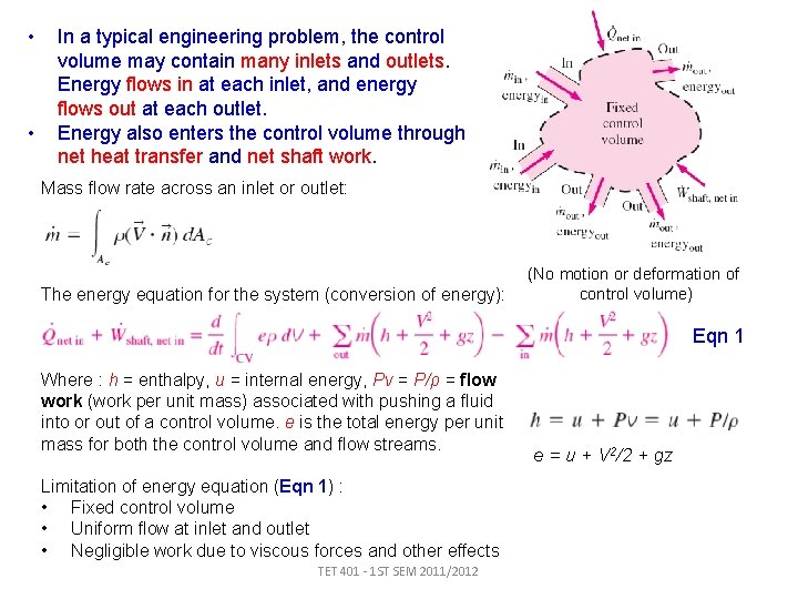
• • In a typical engineering problem, the control volume may contain many inlets and outlets. Energy flows in at each inlet, and energy flows out at each outlet. Energy also enters the control volume through net heat transfer and net shaft work. Mass flow rate across an inlet or outlet: The energy equation for the system (conversion of energy): (No motion or deformation of control volume) Eqn 1 Where : h = enthalpy, u = internal energy, Pv = P/ρ = flow work (work per unit mass) associated with pushing a fluid into or out of a control volume. e is the total energy per unit mass for both the control volume and flow streams. Limitation of energy equation (Eqn 1) : • Fixed control volume • Uniform flow at inlet and outlet • Negligible work due to viscous forces and other effects TET 401 - 1 ST SEM 2011/2012 e = u + V 2/2 + gz
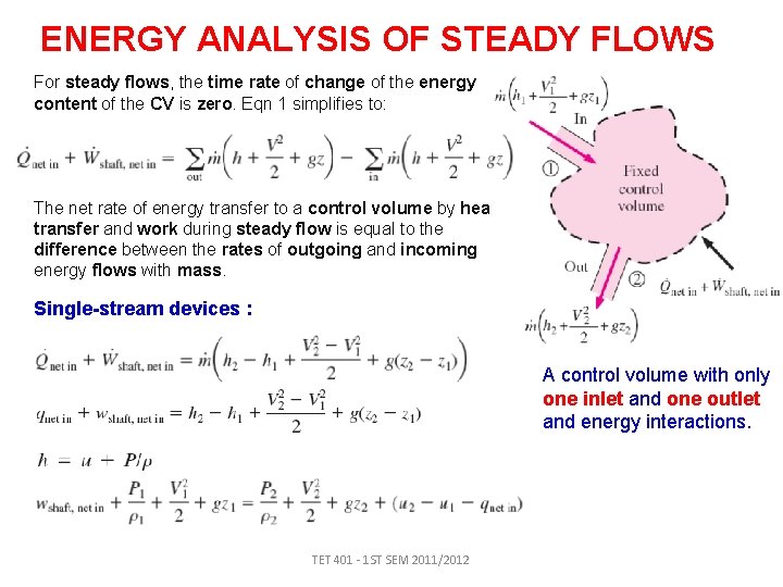
ENERGY ANALYSIS OF STEADY FLOWS For steady flows, the time rate of change of the energy content of the CV is zero. Eqn 1 simplifies to: The net rate of energy transfer to a control volume by heat transfer and work during steady flow is equal to the difference between the rates of outgoing and incoming energy flows with mass. Single-stream devices : A control volume with only one inlet and one outlet and energy interactions. TET 401 - 1 ST SEM 2011/2012
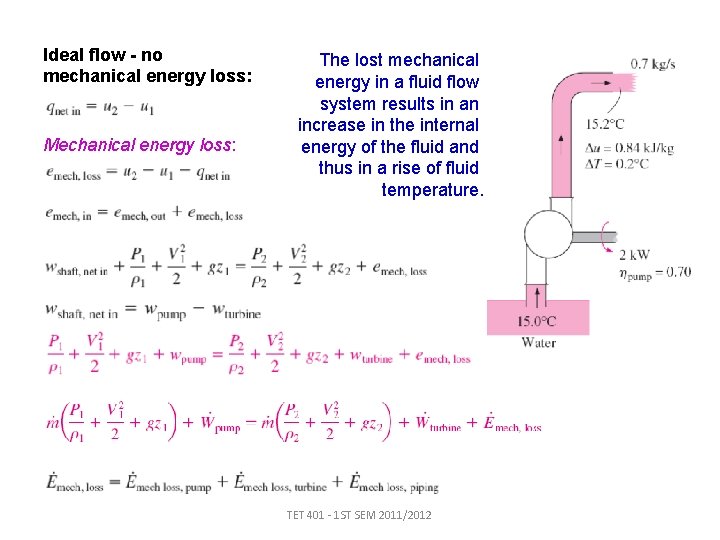
Ideal flow - no mechanical energy loss: Mechanical energy loss: The lost mechanical energy in a fluid flow system results in an increase in the internal energy of the fluid and thus in a rise of fluid temperature. TET 401 - 1 ST SEM 2011/2012
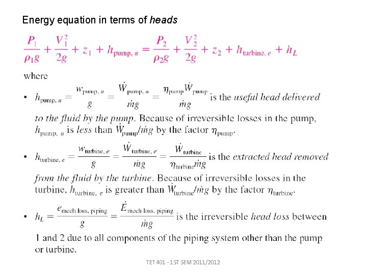
Energy equation in terms of heads TET 401 - 1 ST SEM 2011/2012
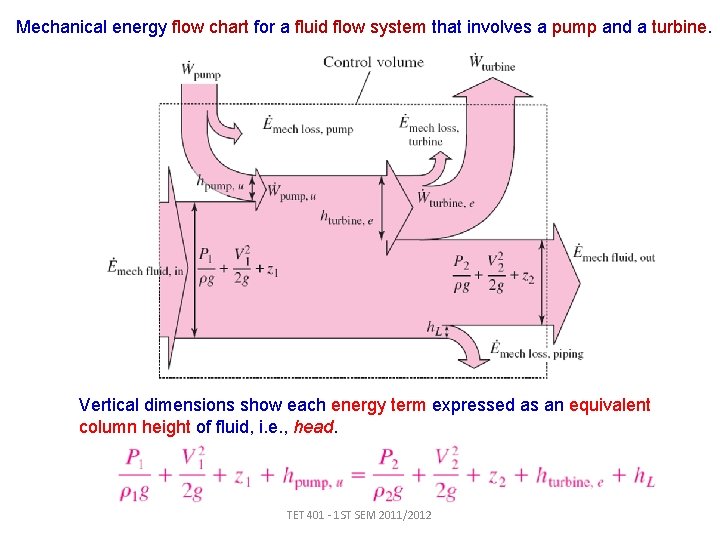
Mechanical energy flow chart for a fluid flow system that involves a pump and a turbine. Vertical dimensions show each energy term expressed as an equivalent column height of fluid, i. e. , head. TET 401 - 1 ST SEM 2011/2012
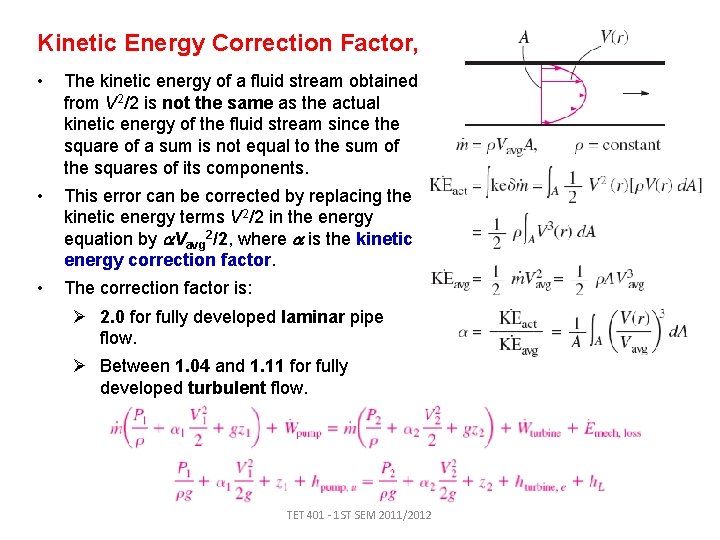
Kinetic Energy Correction Factor, • The kinetic energy of a fluid stream obtained from V 2/2 is not the same as the actual kinetic energy of the fluid stream since the square of a sum is not equal to the sum of the squares of its components. • This error can be corrected by replacing the kinetic energy terms V 2/2 in the energy equation by Vavg 2/2, where is the kinetic energy correction factor. • The correction factor is: Ø 2. 0 for fully developed laminar pipe flow. Ø Between 1. 04 and 1. 11 for fully developed turbulent flow. TET 401 - 1 ST SEM 2011/2012
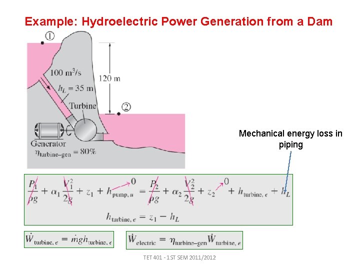
Example: Hydroelectric Power Generation from a Dam Mechanical energy loss in piping TET 401 - 1 ST SEM 2011/2012
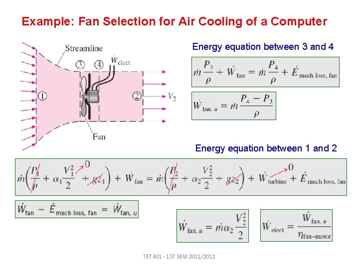
Example: Fan Selection for Air Cooling of a Computer Energy equation between 3 and 4 Energy equation between 1 and 2 TET 401 - 1 ST SEM 2011/2012
- Slides: 35